Toy Motor Speed Control
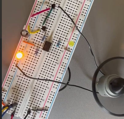
An ATTiny85 with PWM is used to vary the speed of a toy motor that was taken from an outgrown and broken toy car. This was first published on Medium here: https://medium.com/@lfoster.se.be/driving-a-salvaged-toy-motor-0bc64ebf7cb8?sharedUserId=lfoster.se.be
Supplies
- Breadboard and wires
- 5 volt power supply (three 1.5 volt batteries will do)
- Two 220Ω resistors
- One 100Ω resistor
- One 100µF capacitor
- Two pn2222 transistors, or equivalents
- Two LEDs
- ATTiny85 microcontroller (~$1.66 USD)
- SNAP programmer (~$11 USD)
- Toy car motor, or small electronics motor
- Fan of some kind, or any other 'load.'
- Free MPLABX IDE installed on a computer
- USB cable for SNAP programmer
Wire the Circuit
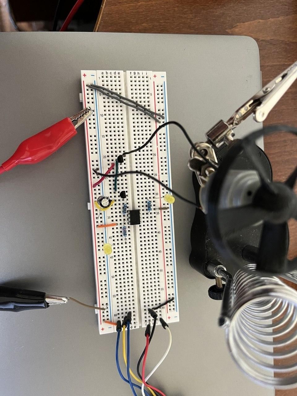
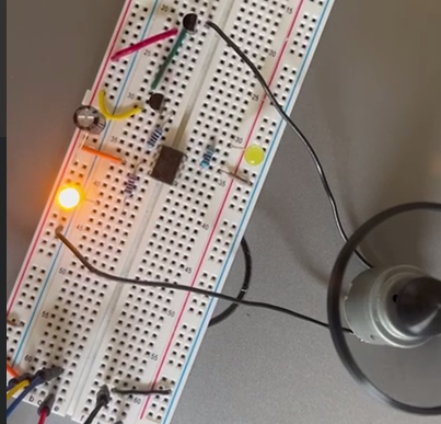
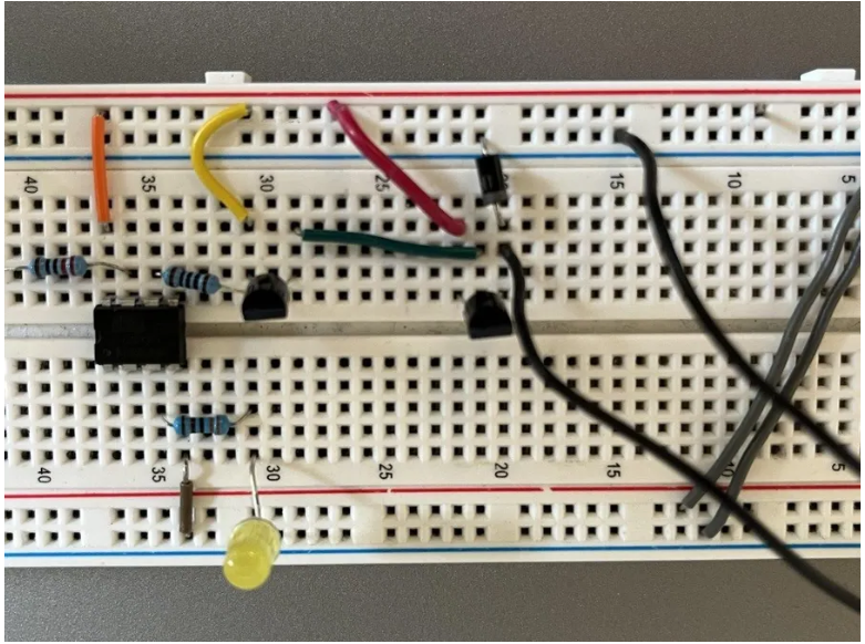
The first image above includes the motor sitting on a "helping hands" device, but you can just place it wherever works for you. The third image is a closer shot so you can see where all the wires are going. We will refer to that below.
There is a black rectangle in the image. That is the (only 8-pin) ATTiny85. These connections are to and from the ATTiny85. We will also call this one the "MCU", or microcontroller unit.
- The orange lead at top-left is the VCC or “power”
- The grey lead at the bottom-right is the ground
- There is a 220Ω resistor running from pin next to VCC. It is connected to the PWM-indicator LED. LEDs always need a resistor in series
- There is another 220Ω resistor running from the pin beside ground, to the “power on” indicator LED. That one always stays lit without PWM as long as the power supply is active
- There is a final resistor connection at two-pins away from power on the “power” side. That is a 100Ω resistor, and its other end is connected to the base (middle) pin of transistor Q1.
There are two pn2222 transistors that are in a "darlington connection" to provide enough power to the motor. Here is how they are wired.
- The second-from-bottom-left pin of the MCU, to the 100Ω resistor, and then to the base pin one of the transistors. Always check your transistor data sheet, but the middle leg is shown as the base pin above.
- That transistor's collector leg is then wired directly to the power of the breadboard.
- The transistor's emitter leg is then connected to the base pin of the second transistor.
- The second transistor's collector pin is also connected to power.
- The second transistor's emitter pin, finally, is what is wired to the motor's power input lead.
- The motor's ground wire is connected to the breadboard's ground
Lastly, and very importantly, the 100µF capacitor's positive pin is connected to power and its negative pin is connected to ground. The placement of the capacitor is very important. This may not be shown in all images, but refer to the one with the fan spinning. Its power lead should go upstream of the transistor power leads. If it is put between the transistor and the motor, it could allow the motor to spin constantly.
Wire the SNAP and Program
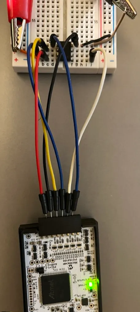
This is not an Arduino project. If you were to program an Arduino with PWM output and connect the PWM output to the base of the first transistor as described above, no guarantees, but you should be able to control the motor and its fan. Indeed, the ATTiny85 can be programmed using Arduino as an In-system Programmer, but I have found it is becoming difficult to find implementations for the ATTiny85. Commenters with more information are encouraged to provide sources. Not having as much luck in the past, I chose to do this with the manufacturer's less expensive programmer: the SNAP.
You will also need to wire a breadboard to do that programming. That wiring is shown in the image above. For reference, the ATTiny85 pinout is shown as well. You will have to pay attention to the little dip in one end of the chip in order to place it properly.
- SNAP Pin 2 — MCU VCC
- SNAP Pin 3 — MCU GND
- SNAP Pin 4 — MCU MISO / Pin 6 / two pins below VCC
- SNAP Pin 5 — MCU SCK / Pin 7 / one pin below VCC
- SNAP Pin 6 — MCU RESET / Pin 1 / opposite from VCC
- SNAP PIN 7 — MCU MOSI / Pin 7 / three pins below VCC
The code for this step is attached as "main.c". If you wire the project as described above and shown in the images, it should work. However, you will have to build an MPLABX project in the IDE. There is a how-to from the manufacturer at this link: https://skills.microchip.com/mplab-x-ide-getting-started-and-programming-an-mcu-application .