Traffic Light System
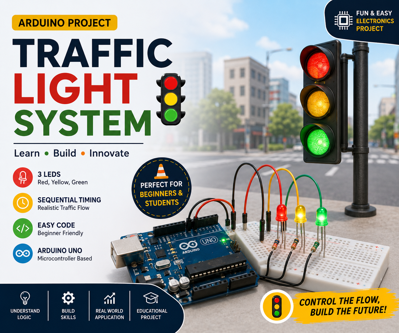
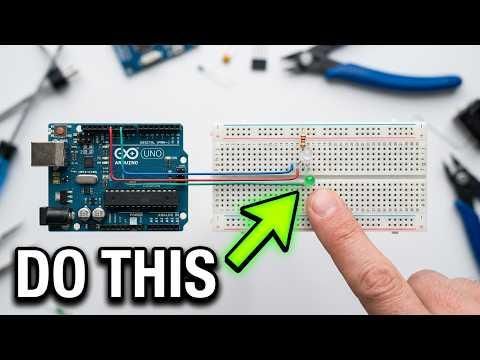
Traffic lights are used worldwide to control vehicle and pedestrian movement safely. In this project, you will build a simple Arduino-based Traffic Light System using three LEDs (Red, Yellow, and Green).
This project is ideal for beginners learning:
- Arduino programming
- Digital outputs
- LED interfacing
- Basic automation concepts
- Real-world control systems
What You'll Learn
✅ Connecting LEDs to Arduino
✅ Using resistors correctly
✅ Writing Arduino code
✅ Understanding traffic signal timing
✅ Uploading code and testing circuits
Supplies
Component Quantity
Arduino Uno 1
Breadboard 1
Red LED 1
Yellow LED 1
Green LED 1
220Ω Resistor 3
Jumper Wires 6
USB Cable 1
Understanding Traffic Signals
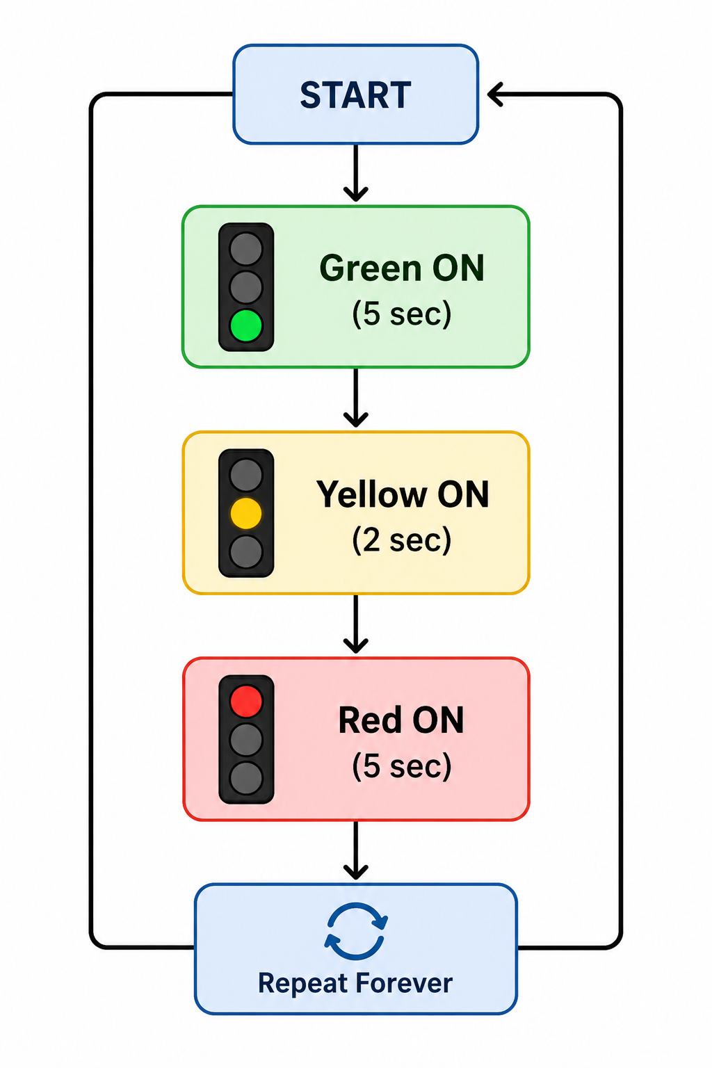
A typical traffic signal follows this sequence:
Signal Meaning
ColorMeaning
Green Go
Yellow Prepare to Stop
Red Stop
Our Arduino will control the LEDs in the same order.
Build the Circuit
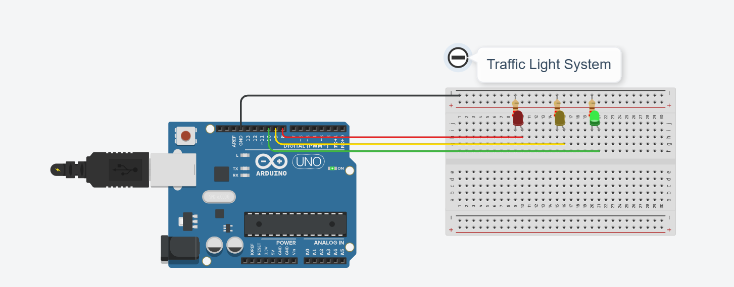
Create the Circuit in Tinkercad
- Open Tinkercad
- Click Circuits
- Create New Circuit
- Add:
- Arduino Uno
- Breadboard
- 3 LEDs
- 3 Resistors (220Ω)
- Wire components according to Step 4
Your circuit should resemble a miniature traffic signal.
Arduino Programming
Click Code → Text Mode and paste the following code.
Code Explanation
Define Pins
Stores LED pin numbers.
Configure Outputs
Sets LED pins as outputs.
Turn Green ON
Vehicle traffic may proceed.
Wait
Keeps green light active for 5 seconds.
Yellow Signal
Warning signal before red.
Red Signal
Traffic stops.
Start Simulation
Click:
You should observe:
- Green LED ON
- Yellow LED ON
- Red LED ON
- Cycle repeats continuously
Testing Checklist
✔ Green LED glows first
✔ Yellow LED glows second
✔ Red LED glows third
✔ LEDs switch automatically
✔ No LED remains permanently ON
How It Works
Real-World Applications
- Road Traffic Control
- Railway Crossing Systems
- Industrial Warning Systems
- Smart City Infrastructure
- Parking Management Systems
- Vehicle Control Systems
Conclusion
You have successfully built an Arduino Traffic Light System that mimics a real-world traffic signal. This project teaches the fundamentals of Arduino programming, digital outputs, timing control, and automation logic.
Next Project Ideas
- Smart Traffic Light with Push Button
- Pedestrian Crossing System
- Traffic Density-Based Signal
- Smart Parking System
- IoT Traffic Management System