Troubleshooting a Weather Station That Will Not Respond on Modbus
by taste_the_code in Circuits > Sensors
114 Views, 0 Favorites, 0 Comments
Troubleshooting a Weather Station That Will Not Respond on Modbus
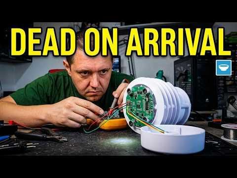
A brand new compact weather station arrived for a project I was working on, and it was completely dead. It would not answer on any address, and it did not even draw current from the bench supply. Instead of shipping it back and waiting weeks, I opened it up and tracked the fault down to a single solder joint that looked perfectly fine and carried no current at all. This walkthrough shows you the whole diagnostic process, which applies to any RS485 or Modbus sensor that refuses to talk, and it ends with a repair you can do with a soldering iron and a multimeter. Before you start, gather the hardware and tools listed in the next step.
This Instructable is sponsored by PCBWay. PCBWay offers services for PCB manufacture and assembly, 3D printing, CNC machining and covers all of your manufacturing needs under one roof.
Supplies
On the hardware side you need the sensor you are diagnosing, which in my case is a compact all in one weather station that measures temperature, humidity, wind speed and direction, atmospheric pressure, rainfall and light intensity, and communicates over RS485 using the Modbus protocol. You also need a USB to RS485 converter dongle, which is a cheap generic adapter with screw terminals for the A and B communication lines, plus the cable that came with the sensor and ideally a second known good cable for comparison. For power you need a bench power supply that can display current draw, set anywhere in the 9 to 24 volt range that these stations accept. The current display matters a lot here, so use a bench supply rather than a plain wall adapter if you can.
For software you need Python installed with a virtual environment, and a Modbus client tool that can scan the address range and read registers. I use a tool I wrote myself that talks to the serial port on the converter, wraps requests in Modbus format, and decodes the replies for each sensor type I own. Any Modbus RTU master utility will do the same job.
For tools you need a multimeter with a continuity mode, a soldering iron with fine solder, a Phillips screwdriver, a set of Allen keys, isopropyl alcohol with a small brush or cotton swab, and a hot glue gun for reassembly. Have the sensor datasheet open too, because you will want to check the default address and the register layout against what you actually receive.
- USB to RS485 Converter: https://s.click.aliexpress.com/e/_c3B5sw3Z
- Bench Power Supply: https://s.click.aliexpress.com/e/_c3OJmYiP
- Multimeter: https://s.click.aliexpress.com/e/_c4W35TRd
- Soldering Iron: https://s.click.aliexpress.com/e/_c3k2Ew6J
- Hot Glue Gun: https://s.click.aliexpress.com/e/_c3DVfmMT
- Allen Key Set: https://s.click.aliexpress.com/e/_c3hm08zV
RS485 Weather Station
- Option 1 - https://s.click.aliexpress.com/e/_c3UvwIjv
- Option 2 - https://s.click.aliexpress.com/e/_c4TRf2Xt
- Option 3 - https://s.click.aliexpress.com/e/_c4bGcMXD
Understand How the Sensor Talks
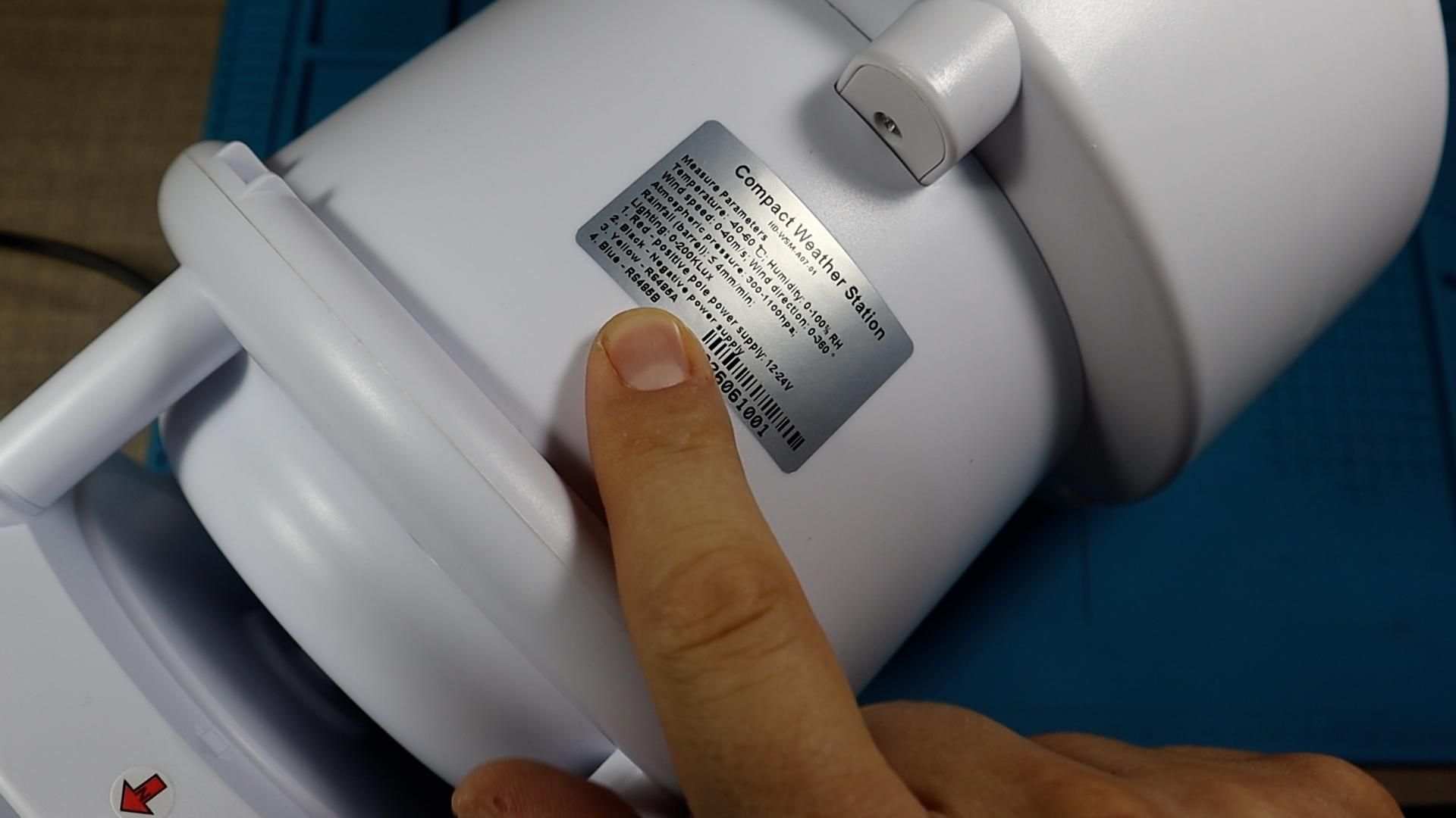
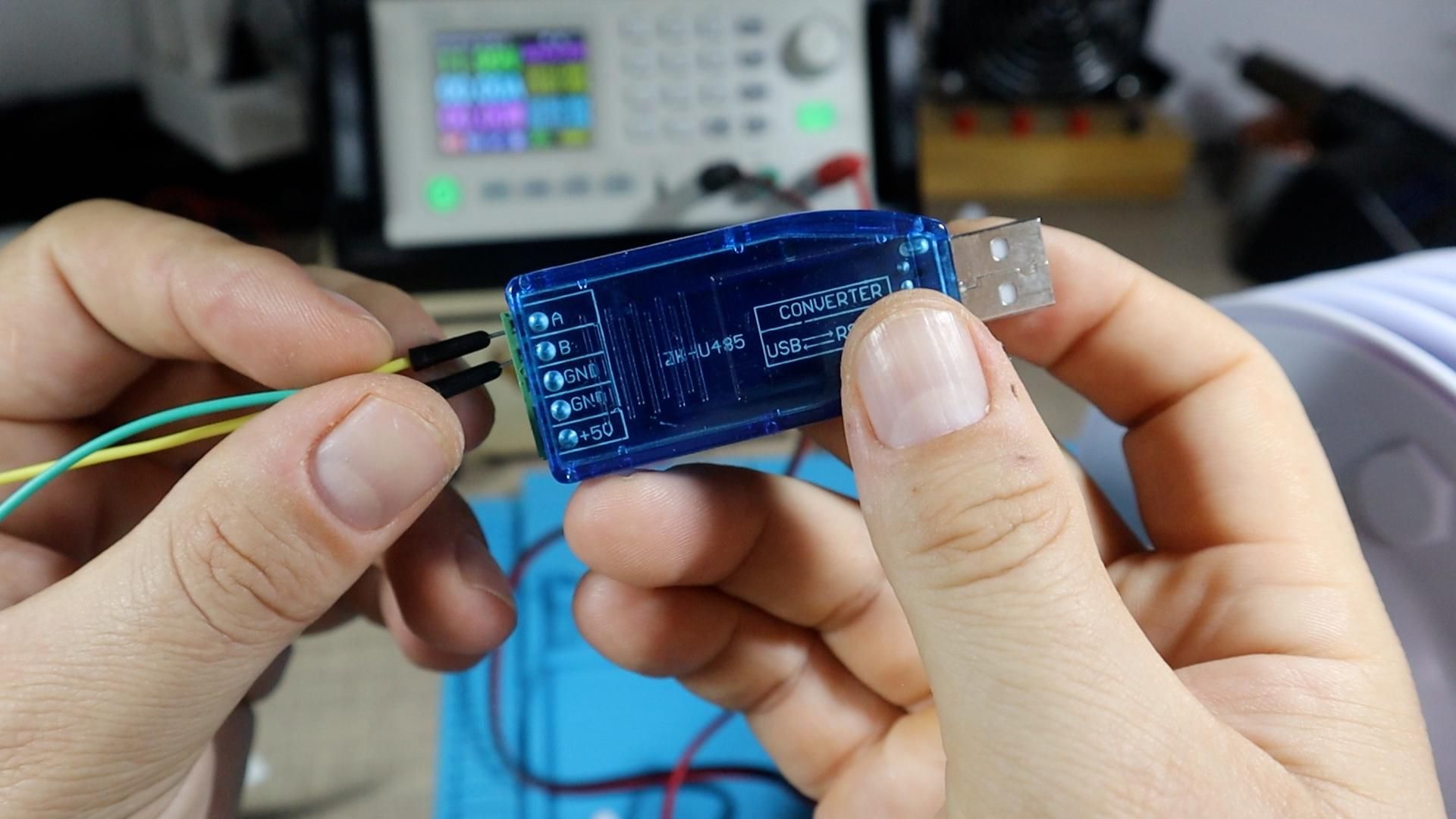
Before you touch anything, it helps to know what should be happening. RS485 is a differential communication standard designed for industrial use. It carries a signal over a twisted pair of wires labelled A and B, it works reliably over long cable runs, and it lets many devices share the same pair. On top of RS485 sits Modbus, which is the actual message format. Every device on the bus has a numeric address, and you request data by sending a command stamped with that address. Only the device with a matching address replies.
That gives you two very different failure modes to separate. Either the sensor is running but sitting on an address you are not asking for, or the sensor is not running at all. Almost every sensor of this type leaves the factory preset to address 1, and it is your job to assign unique addresses once you build a network with several devices on the same bus. Knowing that default is what makes the next few steps meaningful.
Rule Out the Cable First
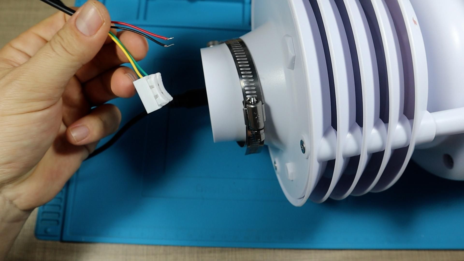
The cable is the cheapest thing to be wrong, so eliminate it before you open anything. Test the sensor's own cable with a different sensor you know works. If that other sensor responds normally, the cable is good. Then do the reverse and connect your dead sensor with a known good cable from a working setup. If it still fails, the cable is fully ruled out and the fault is inside the sensor.
I did both of these checks and the result was the same either way, so the problem had to be internal.
Power It Up and Watch the Current
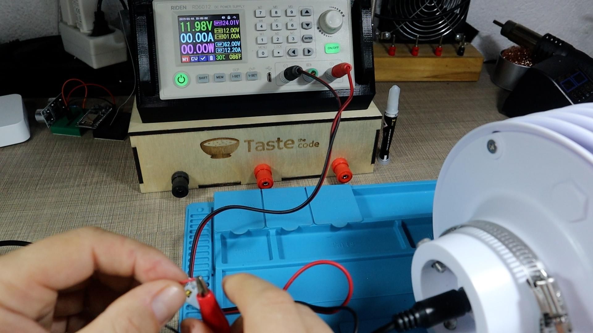
This is the single most useful test in the whole process. Set your bench supply to 12 volts, connect the sensor's power and ground wires, and leave the communication lines disconnected for now. Then watch the current reading.
A healthy sensor pulls at least a small amount of current just to run its microcontroller and regulators, even with nothing on the bus. My supply showed exactly zero. The voltage held steady and no current flowed at all. That single reading told me the device was not running, and a device that is not running will never reply to a Modbus request no matter which address you use.
Scan the Whole Modbus Address Range
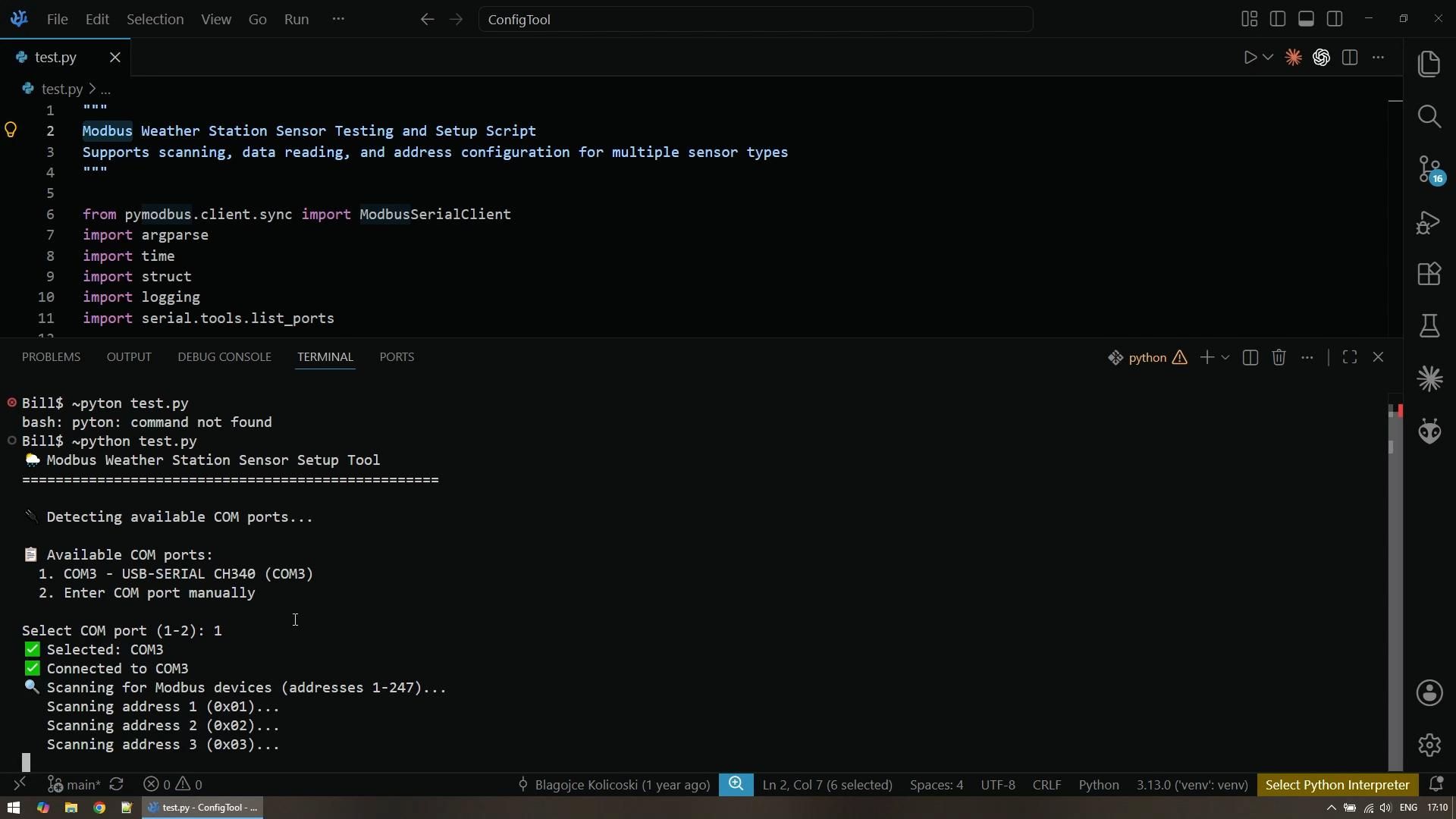
Even with a strong clue from the current draw, confirm it from the software side. Wire the sensor's communication lines into the USB to RS485 converter. Check the label on your sensor for the colour coding, since it varies by manufacturer. On mine, yellow is RS485 A and green is RS485 B, so yellow went into the A terminal and green into the B terminal. Plug the converter into your computer.
Activate your Python virtual environment and start your Modbus tool. It should detect the available COM ports and let you pick the USB to serial adapter, which came up as COM 3 for me. Then run the address scan. The tool sends a ping to every possible Modbus address from 1 up to 247 and reports anything that answers. Let it run all the way to the end.
Mine found nothing on any address. I then checked the datasheet, which confirms 01 as the default, and since nobody had ever powered this unit before, address 1 should have answered. It did not, so the case had to come off.
Open the Housing
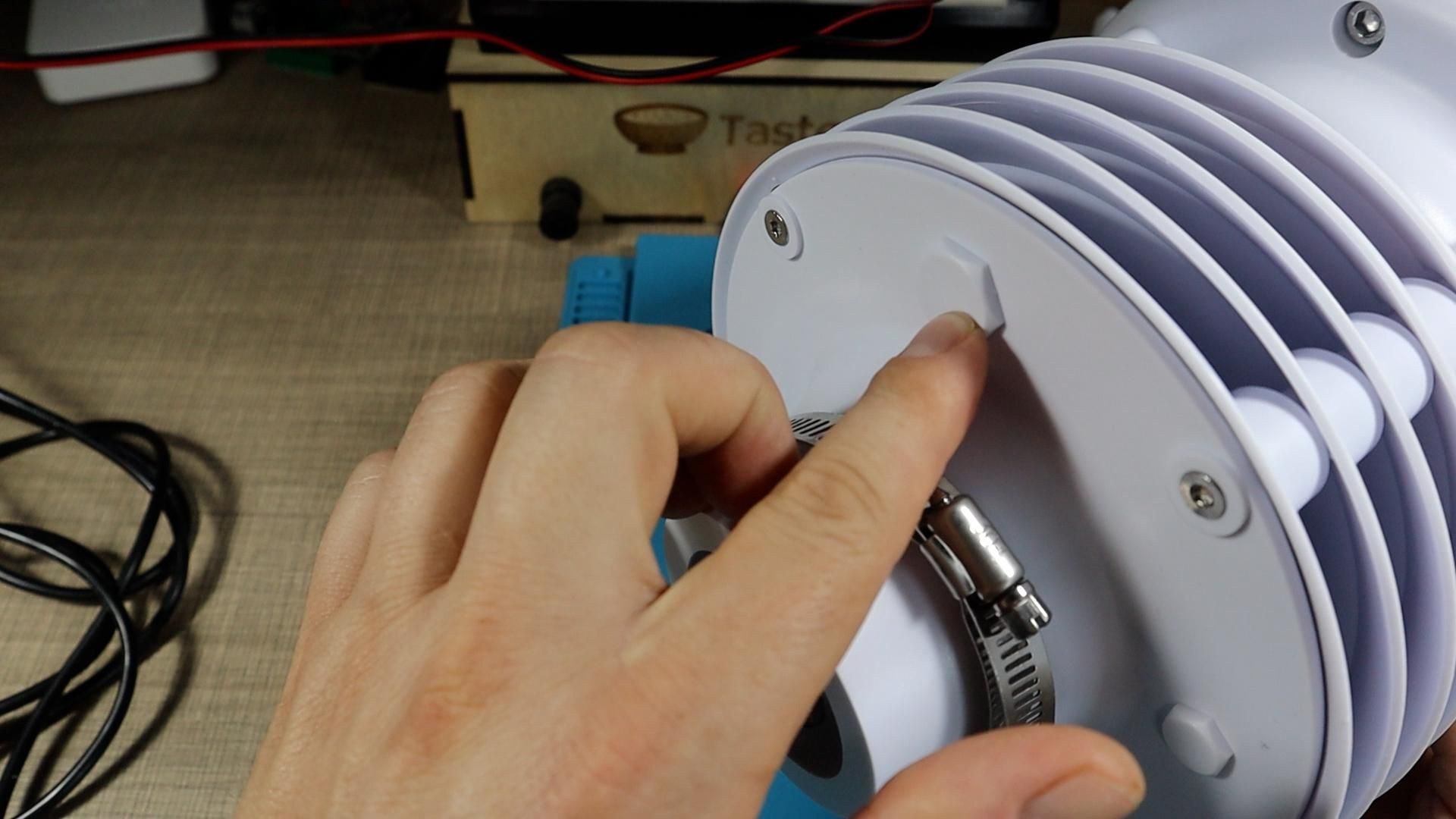
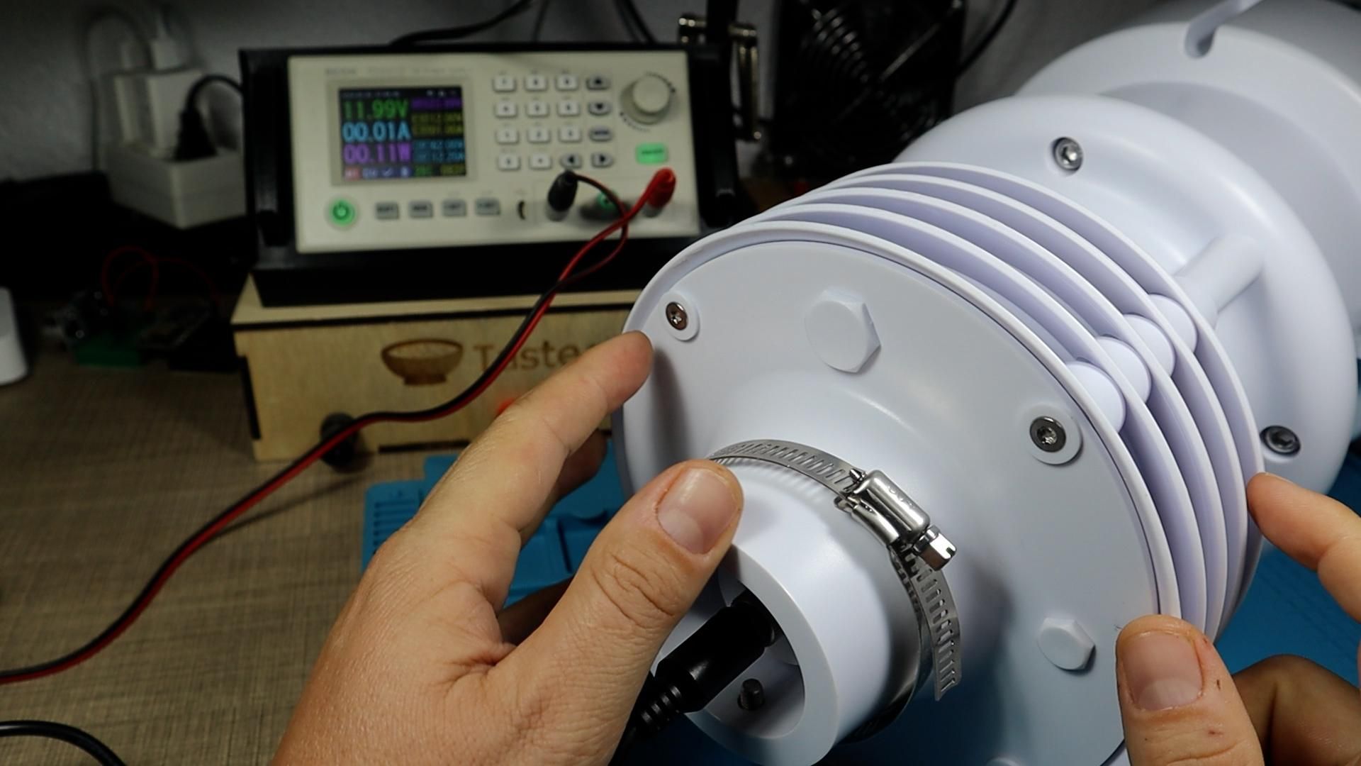
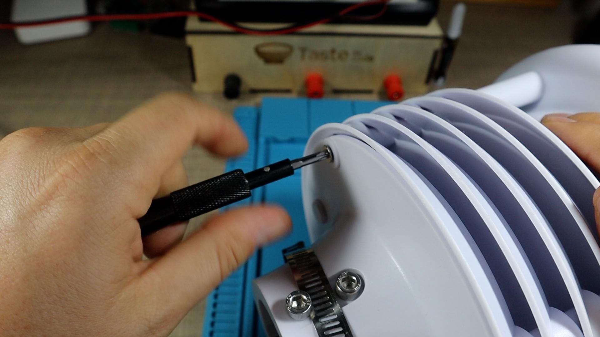
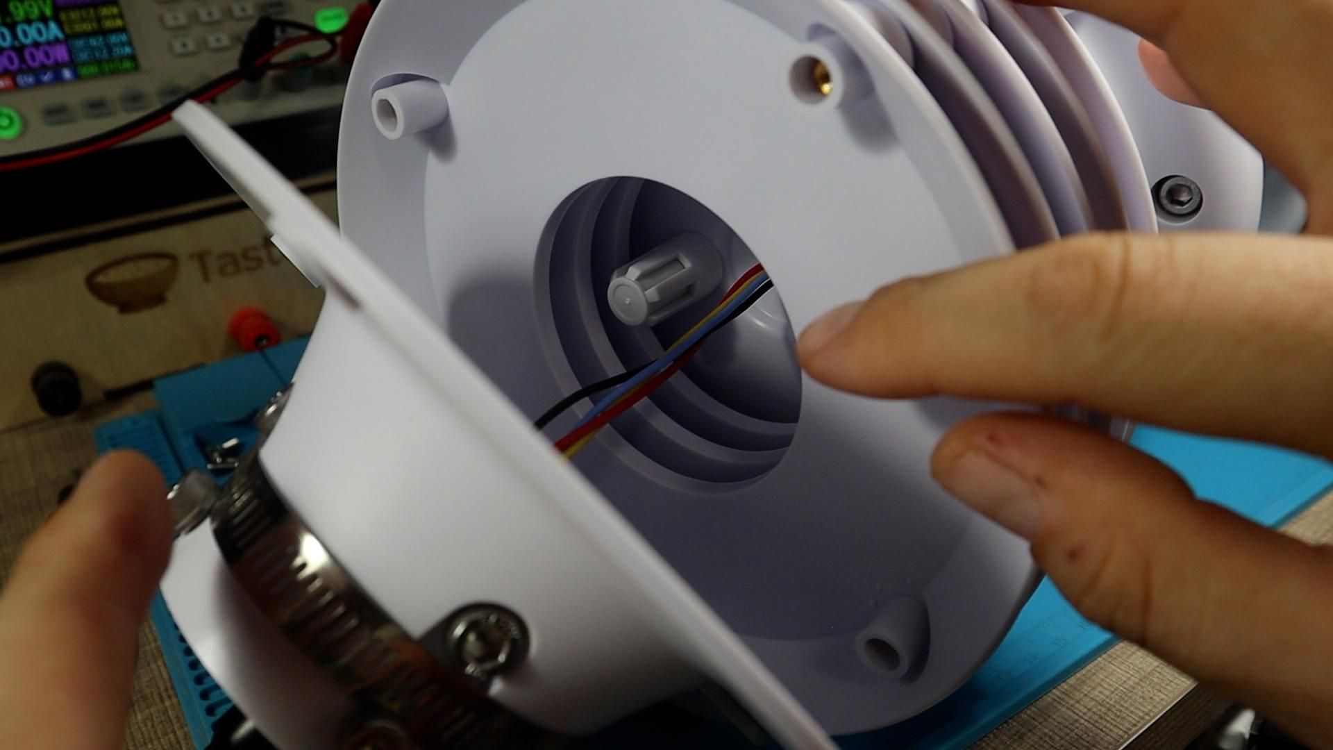
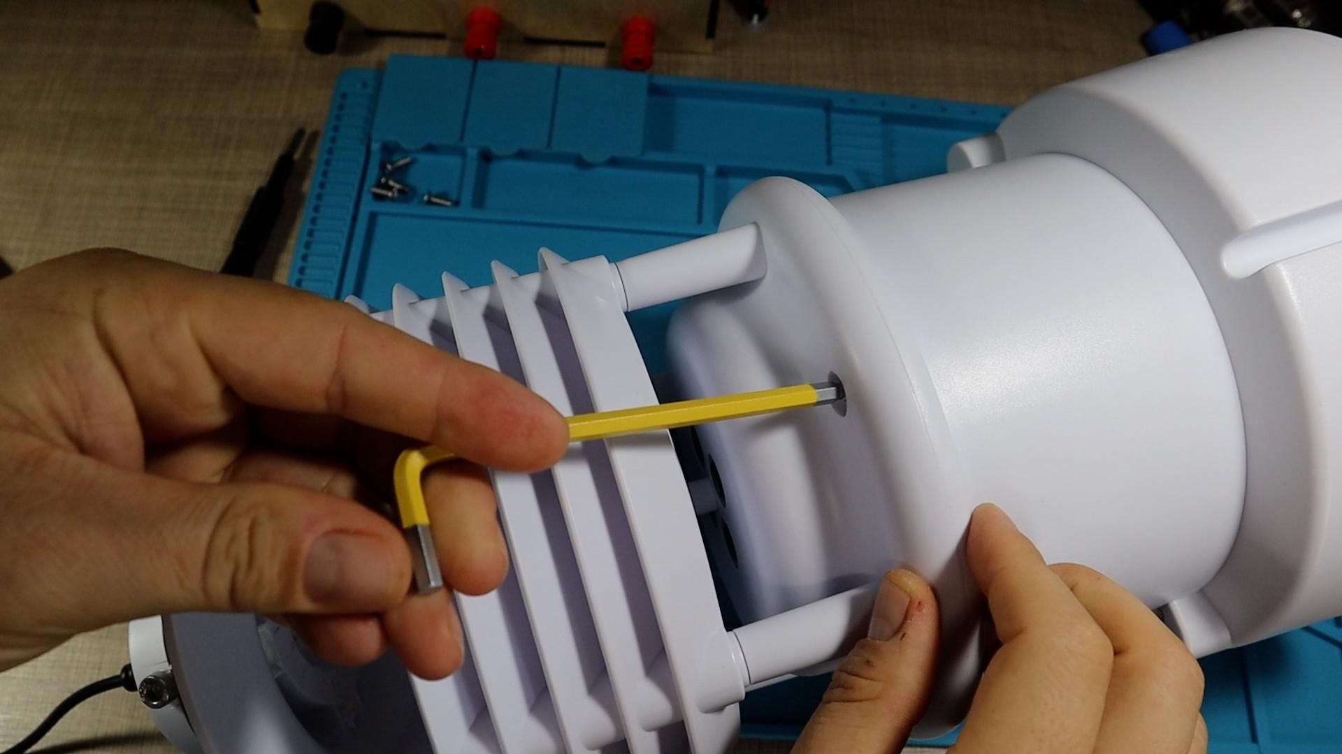
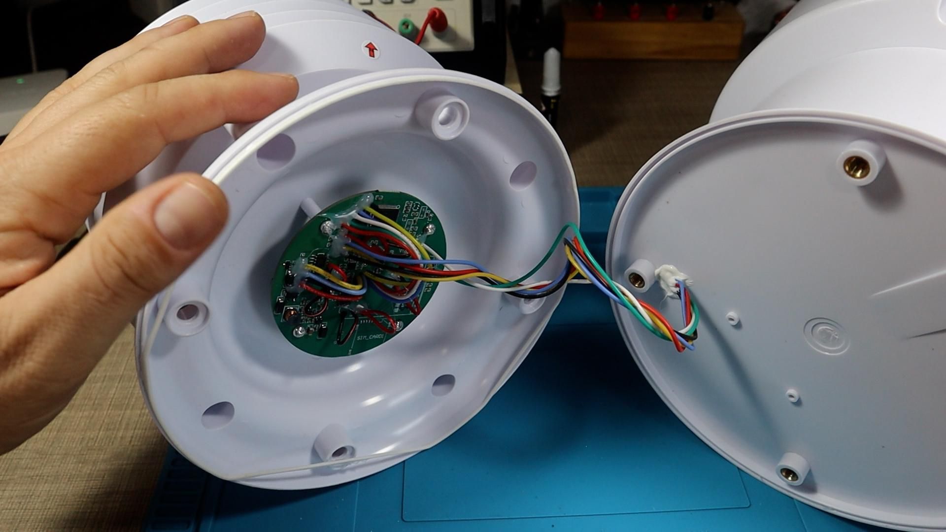
Start on the bottom of the housing. There are several screws to remove, plus a couple of plastic screws that are purely mechanical and tie into the mounting post. With those out the bottom section separates and you can see the internal cables running up through the body, held in place with glue.
To reach the compartment where the PCB lives you need to separate a second section, which uses four Allen bolts on mine. Be aware that even with all the bolts out it may not come apart, because there is a sealant applied in the groove between the sections before the housing is tightened down. It behaves like a liquid glue and it has to be broken to get inside. Work at it gently and evenly rather than forcing one side. That seal is what keeps water out of an outdoor device, so plan on restoring it during reassembly.
Check Continuity From the Connector to the Board
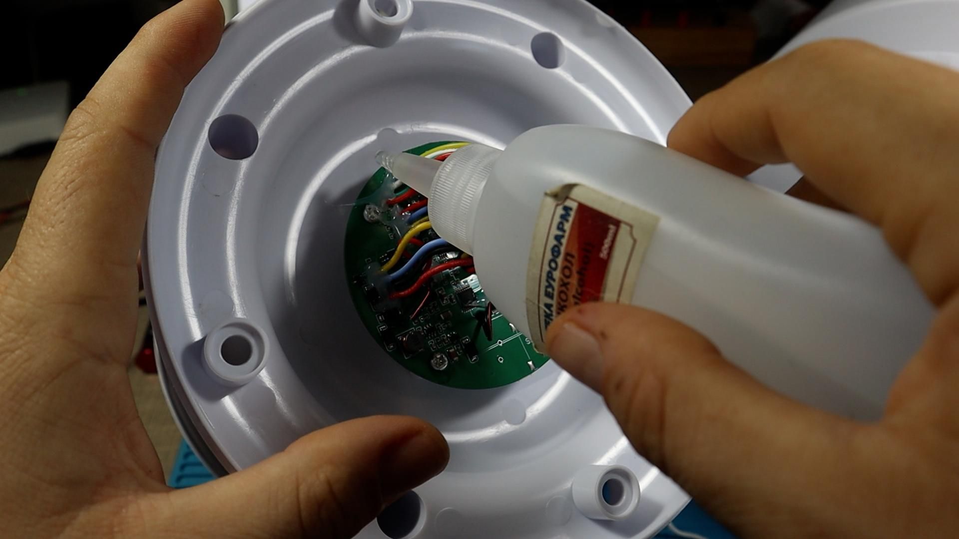
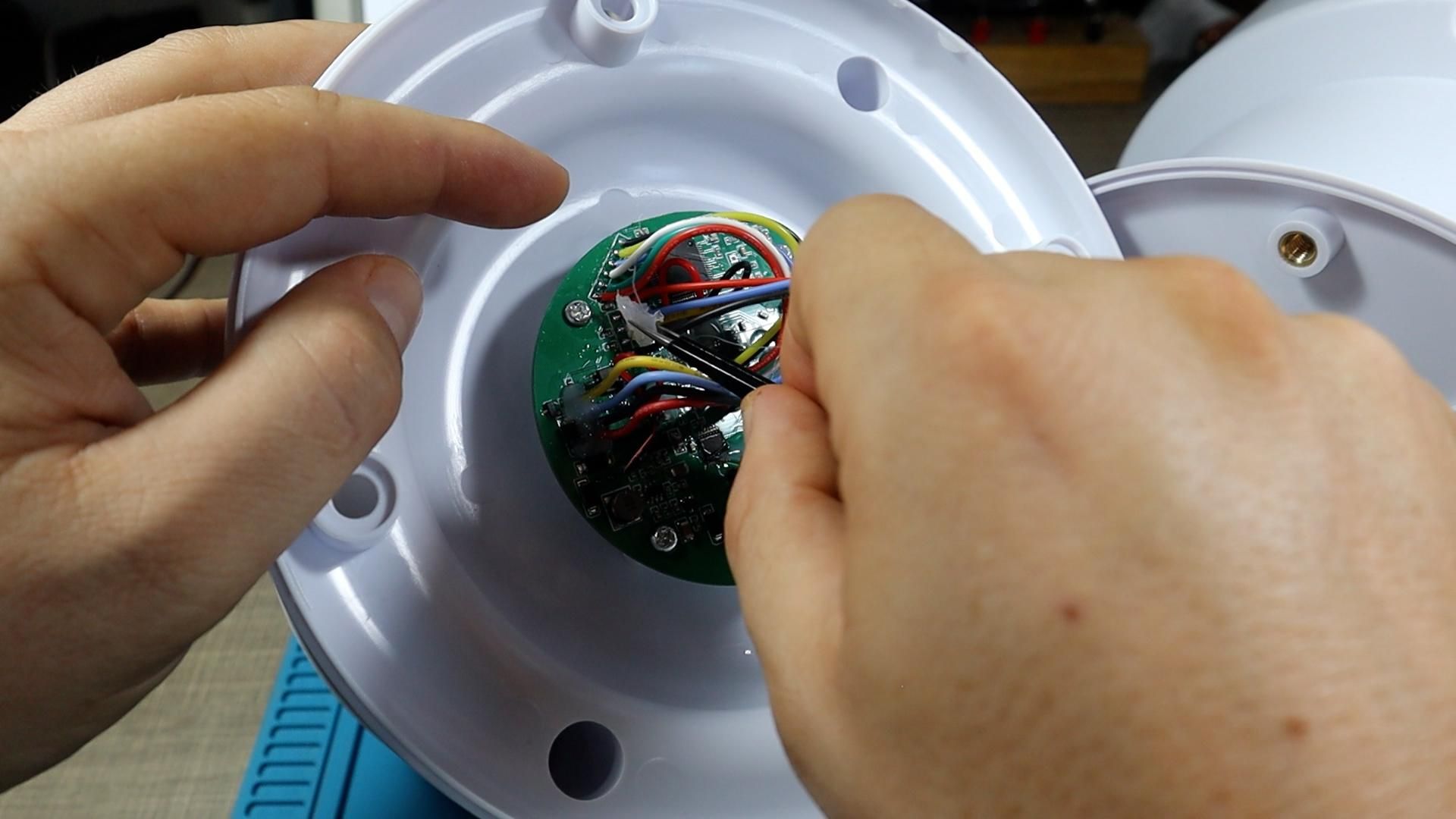
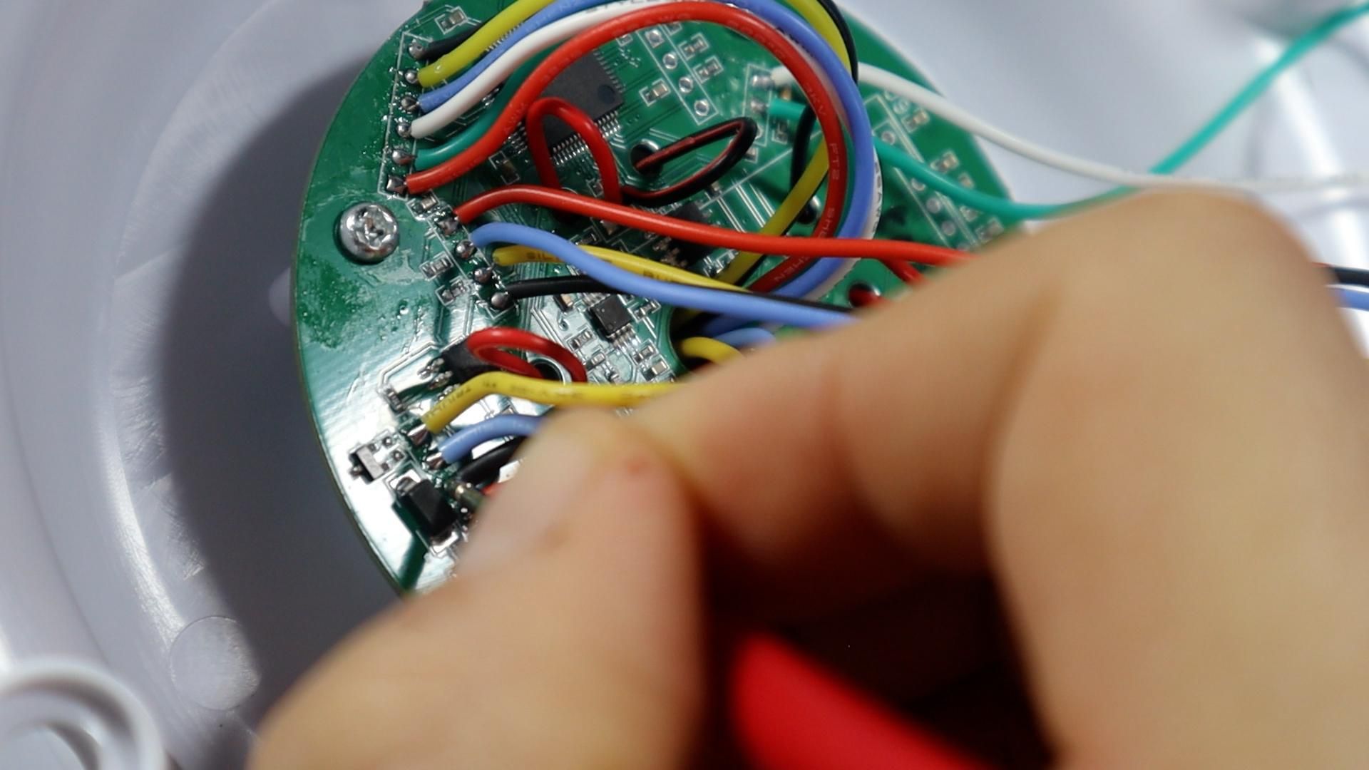
With the PCB exposed, verify that the external cable actually reaches the board electrically. The internal wires are usually tacked down with hot glue, which hides the solder pads. Apply a small amount of isopropyl alcohol to the glue, give it a moment to soften, then gently lift the glue away from the wires until you can see the pads clearly. A little alcohol goes a long way here, so do not soak the board.
Identify the wire bundles. On mine, one bundle came down from the top section for the rain bucket and light sensors, another six wire bundle handled pressure and humidity, and a set of four wires came in from the front connected to the external cable. Those four are the ones you care about.
Put the multimeter in continuity mode and test each one from the outside connector through to its pad on the board. Red is the positive supply, black is ground, and on my unit yellow is RS485 A and green is B. Every wire read just under an ohm, which is a pass. Also probe between different wires to check for shorts, and I found none. So every conductor was intact and nothing was shorted, which pointed the finger at the board itself.
Note the Orientation Before Lifting the Board
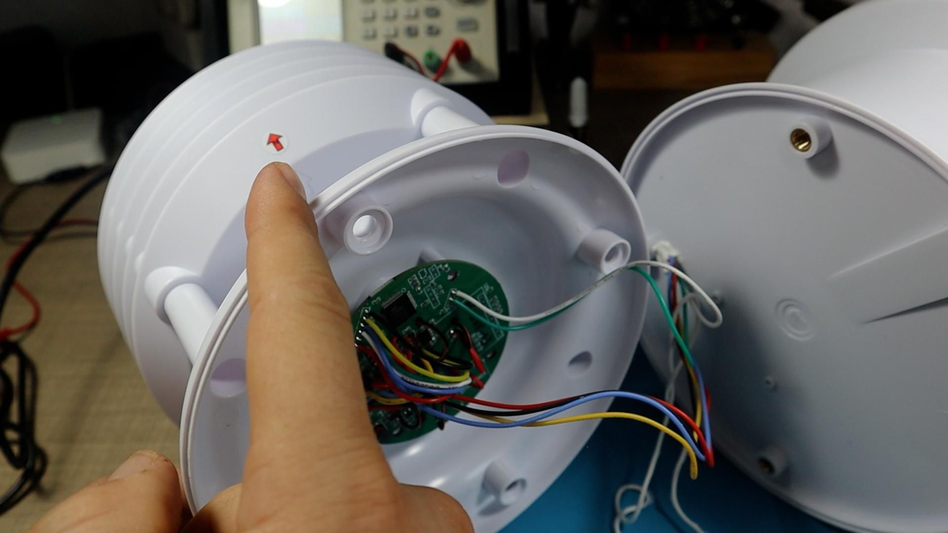
If you plan to remove the PCB, record its rotation first. On my station there is a printed arrow marking the north side for installation, and it exists for a reason. The ultrasonic transducers that measure wind direction have to sit in a specific rotation, so a board reinstalled at the wrong angle will report wind direction incorrectly forever. Note which way the arrow points relative to the housing before anything moves.
I removed all the mounting screws and tried to lift the board, but it would not come free. The four wires going to the ultrasonic transducers are anchored deeper inside the housing, and desoldering all of them just to look at the back of the board was not worth it. Only remove the board if you can do it without cutting or unsoldering things you cannot easily restore.
Probe the Power Rails
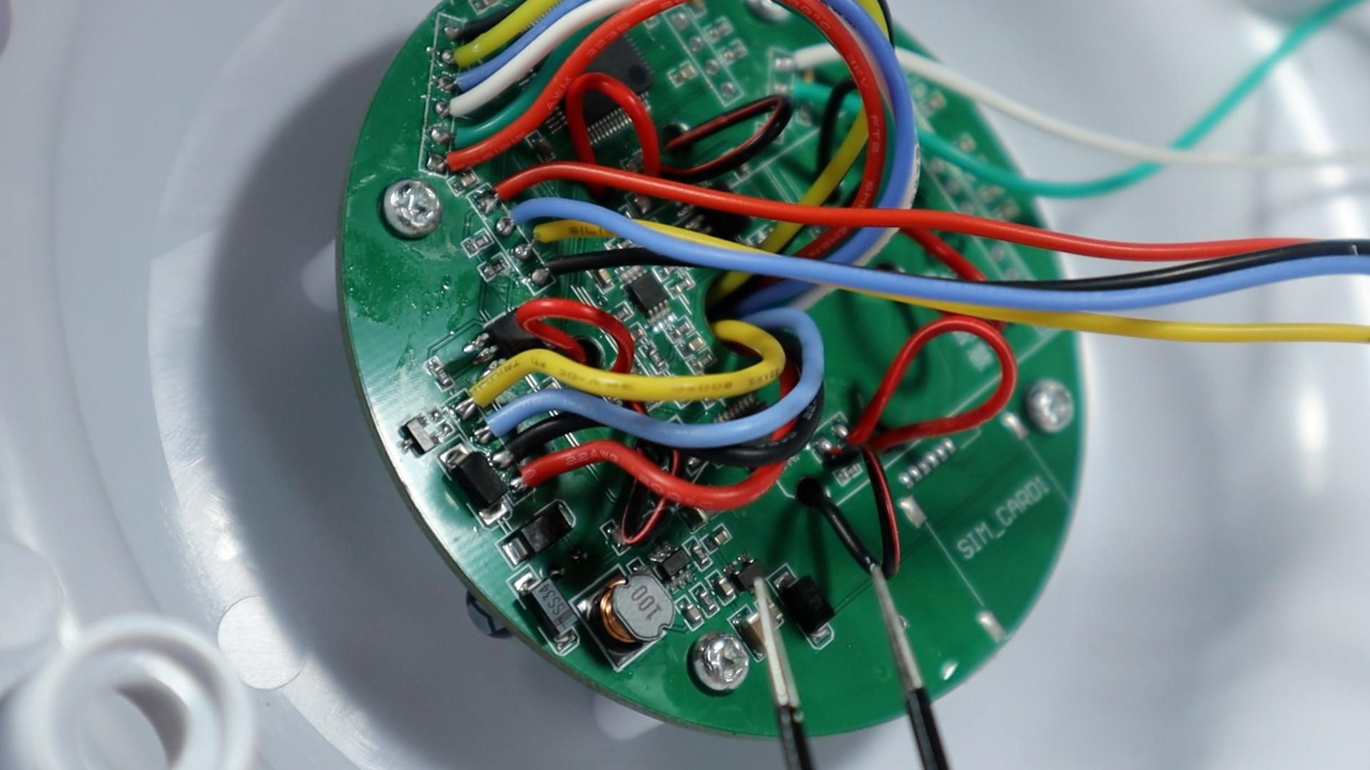
Since I could not flip the board, I powered it up in place and probed around with the multimeter to see how far the voltage travels. Follow the incoming supply from the connector through the protection diodes, then look for capacitors near any regulator style parts and measure across them.
I found 12 volts arriving, then about 4.6 volts on a capacitor after the first regulator, which is close enough to a 5 volt rail. From there the 5 volts continues through a diode to the port feeding the top section. A second regulator produced a clean 3.3 volts on its own capacitor, and both rails were present on the other connectors around the board. In other words the entire power path was healthy, which made the dead behavior even more confusing.
Find the Joint That Looks Good and Is Not
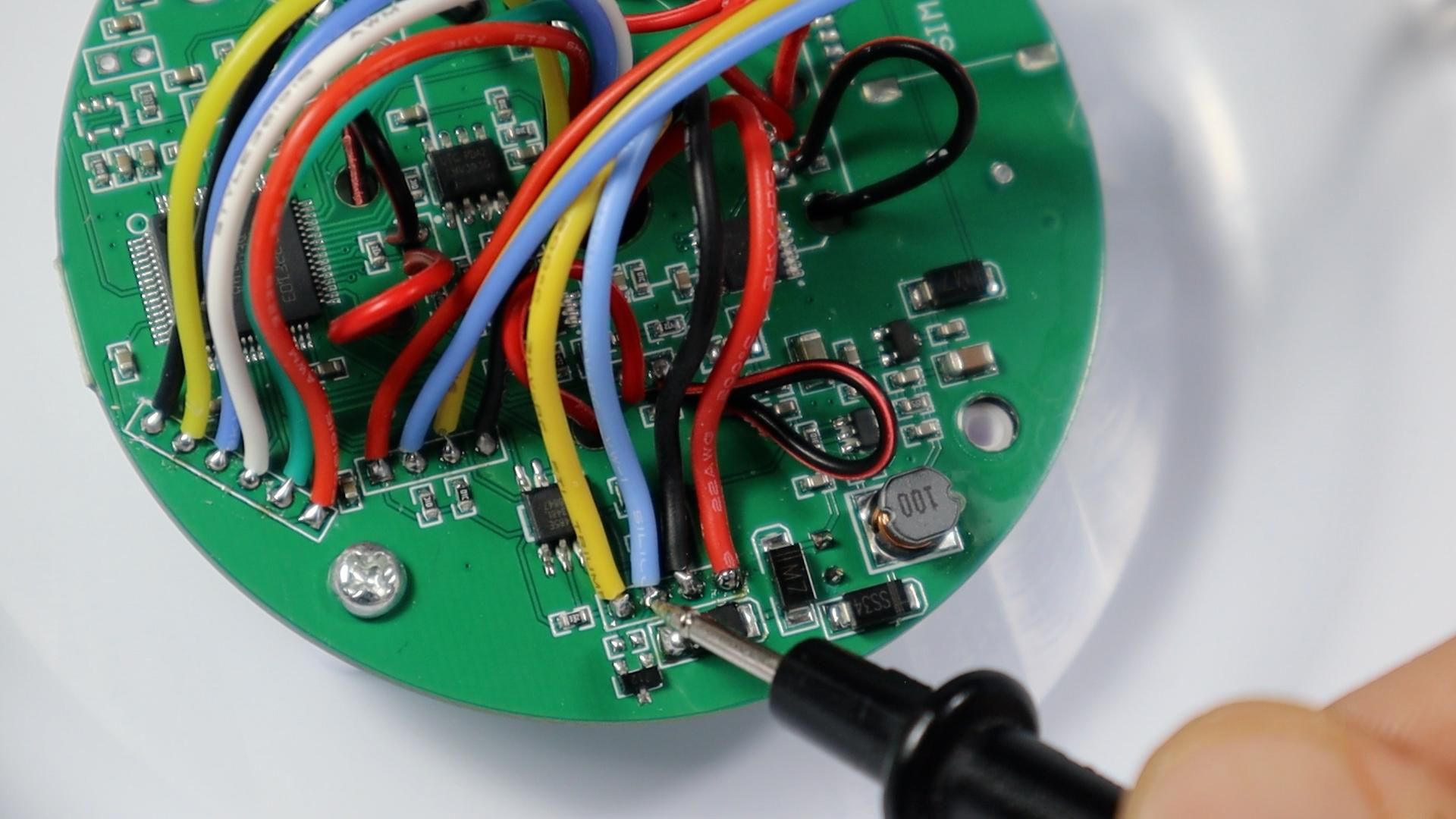
With the power path cleared, go back to continuity testing, but this time trace the copper rather than the wires. Put one probe on an incoming wire and the other on the component or pad that trace should reach.
I noticed two of the incoming wires connect to a small transistor shaped part, probably a filter or protection component. When I checked the second wire through to its destination pin, I could not get continuity no matter how I placed the probes. The wire looked perfectly soldered. It sat flat on the pad, it had solder around it, and it did not move when I nudged it.
The reason this is easy to miss is that the earlier continuity test passed. Probing along the wire itself gives you a good reading, because the wire is fine. The break was in the joint between that wire and the pad, and a hot glue blob over the top was holding the wire mechanically in place so nothing looked or felt wrong.
Resolder the Wires
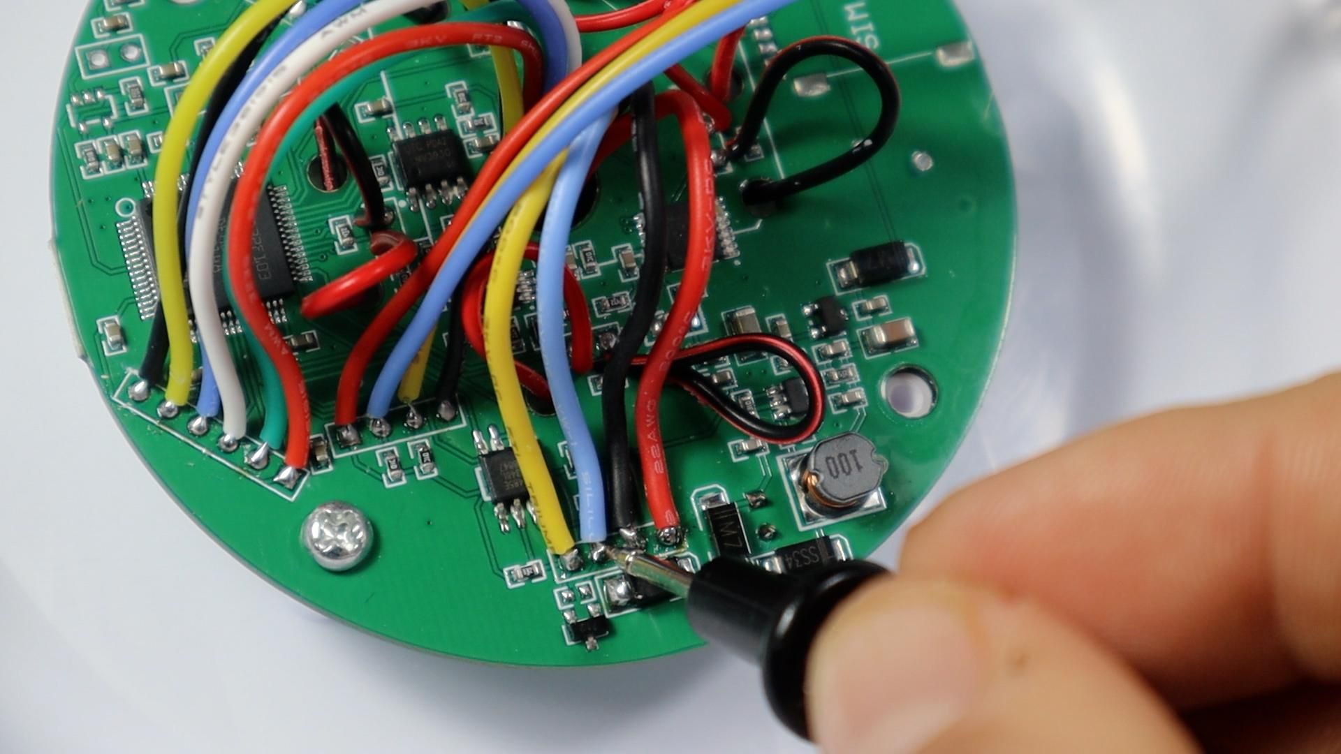
The fix is simple once you know where to look. Heat your soldering iron, remove all the wires in the suspect group, clean the pads, and resolder each wire back to its own pad with fresh solder. Doing the whole group rather than only the one you suspect is worth the extra minute, since a hairline crack in one joint often means the others were made under the same conditions.
As soon as I resoldered those four wires, the station came alive. I never physically saw the crack, so I cannot claim it with certainty, but a hairline fracture in the joint held together by glue is the only explanation that fits what I measured.
Test It
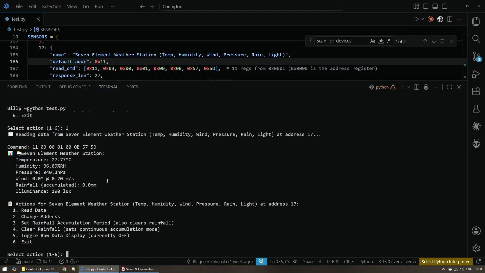
Reconnect the sensor to the converter and the bench supply, then run your Modbus tool again. The first thing to check is current draw. Mine went from a flat zero to 0.01 amps, which is simply the lowest my supply can display, and that alone confirms the device is running.
Run the address scan again. It found the device immediately, so I selected the correct device type in the tool, which for this station is type 17 with seven measured elements, and read the data. I got 27.57 degrees Celsius, relative humidity of about 35 percent, and atmospheric pressure of 940 hectopascals. Wind and rainfall both read zero, which is exactly right for a station sitting indoors on a bench.
The light sensor is the best way to prove the readings are live rather than cached. Sitting on my bench it reported about 80 lux. I aimed a bench lamp directly at it and read again, and it jumped to 1,230 lux. Turning that lamp off dropped it to 60 lux, which was just the ambient light from my second lamp. I also exercised the write side of the protocol by changing the Modbus address and clearing the accumulated rainfall counter, both of which completed cleanly. Finally I looked at the raw view showing the exact command sent and the exact bytes returned, and compared that against the datasheet to confirm the values were being decoded correctly rather than trusting a nice looking number on screen.
Seal It Back Up
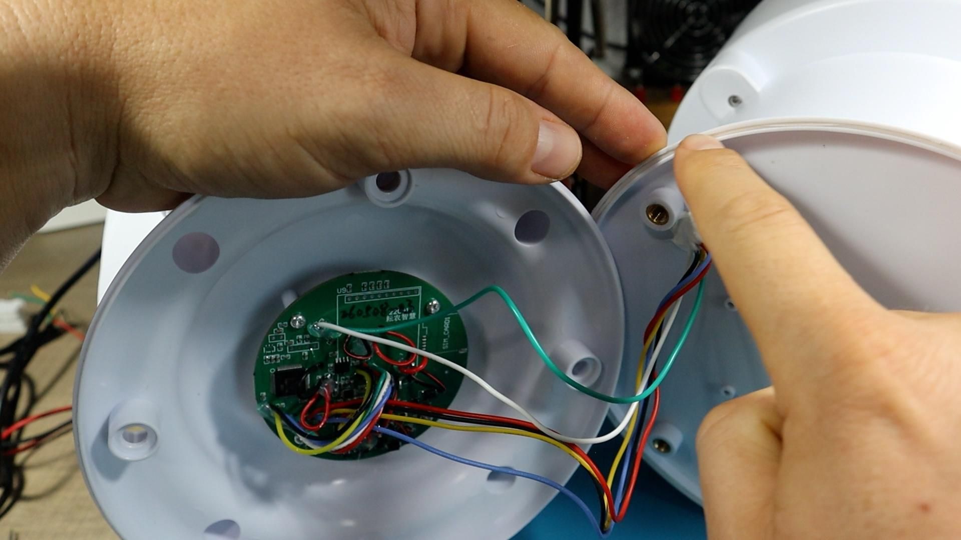
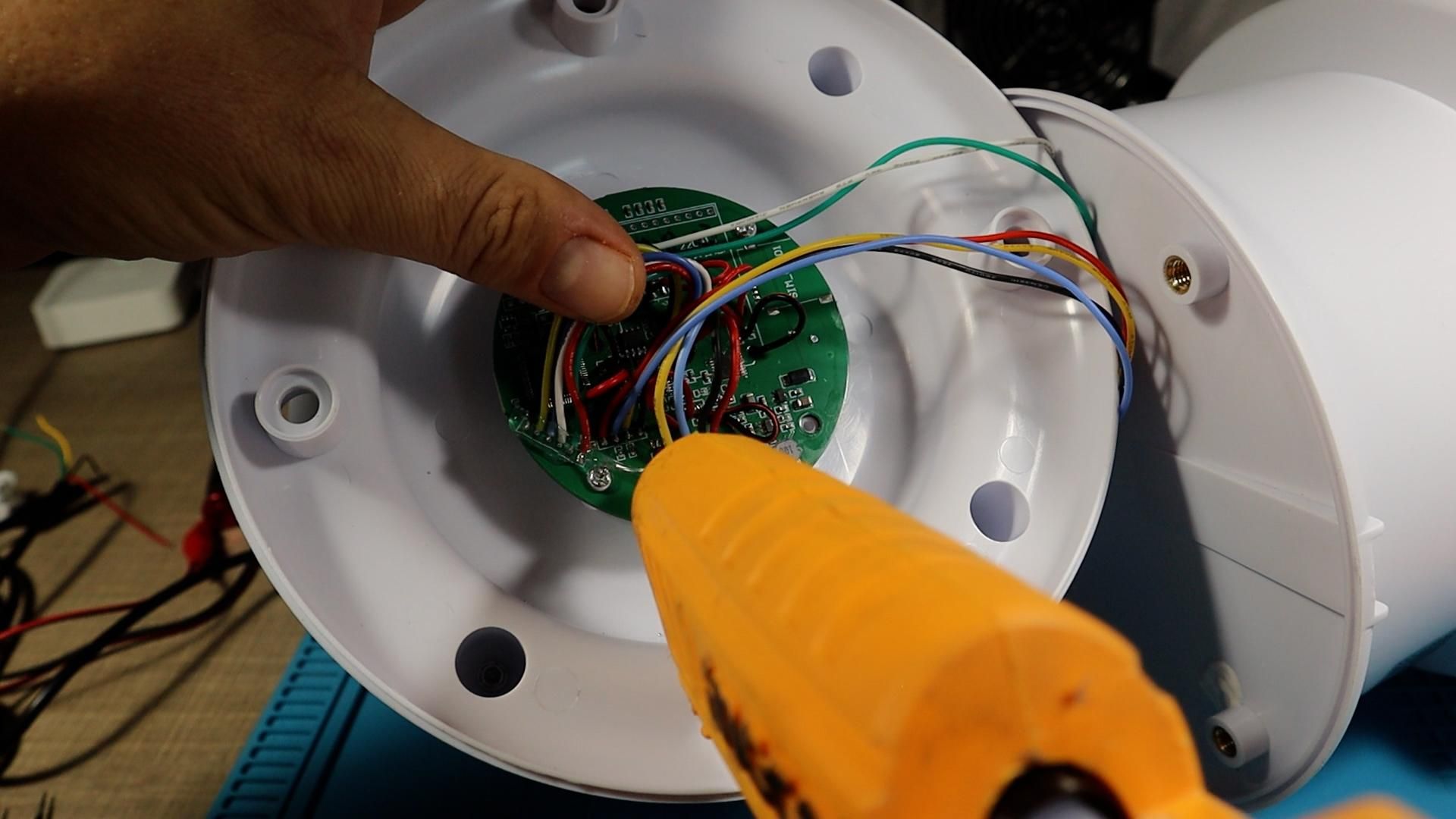
Reassembly is where you can easily create a new fault, so take your time. Apply fresh hot glue over all the cables and solder joints, both to hold them in place and to give the wires strain relief. Let the glue firm up before you move anything.
Press the rubber grommet seal back into the groove in the housing, since that is the only thing keeping rain out of the electronics chamber on an outdoor device. Refit the screws that hold the PCB, then bring the two halves of the housing together while watching that no wire gets pinched between them. A squeezed wire is exactly the kind of intermittent fault you just spent an afternoon chasing. Once the halves seat properly, add the outer screws and run one final read to confirm everything still works fully assembled.
Conclusion
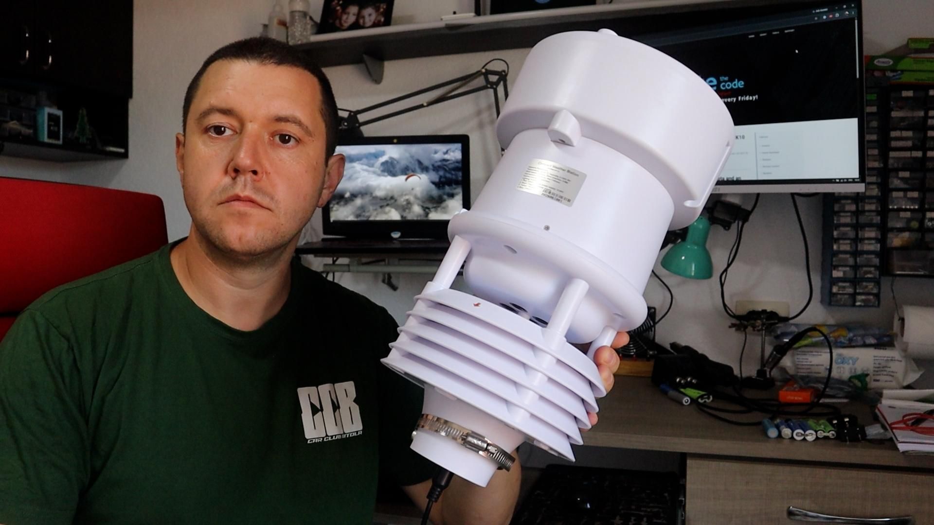
What I like about this repair is how ordinary the fix was compared to how mysterious the symptom looked. Nothing responded across the entire Modbus address range, both voltage regulators tested perfect, and every single wire had continuity, and it still came down to one solder joint carrying nothing. The zero current reading on the bench supply was the most valuable clue in the whole process, and it is now the first thing I check on any sensor that refuses to communicate. If you take one habit away from this, make it that one.
From here you could apply the same sequence to any RS485 or Modbus device that goes quiet, and it is worth building or adapting a small scanning tool of your own since it turns guesswork into a repeatable test. If you enjoy this kind of teardown and repair, follow along on the Taste The Code YouTube channel for more hardware projects and fixes.