Turning an Old ATX PC Power Supply Into a Simple Bench Power Supply
by J_Sanahuja in Workshop > Energy
142 Views, 2 Favorites, 0 Comments
Turning an Old ATX PC Power Supply Into a Simple Bench Power Supply

Can an old PC power supply be reused to power 3.3V, 5V and 12V projects? That’s exactly what I wanted to find out with this old ATX power supply.
I know there are already plenty of projects that turn ATX power supplies into proper bench power supplies, complete with voltage regulators, displays and power meters. But this time I wanted to build something much simpler and more practical: use the voltages the PSU already provides and make them easily accessible for tinkering.
After all, most of the projects I build run on 3.3V, 5V or 12V. I didn’t need another display sitting on my workbench. I just wanted to stop hunting for connectors every time I needed to check whether something worked.
So that’s what you’ll find in this tutorial: a simple way to turn an old ATX PC power supply into a handy power source for testing motors, LEDs or other devices before eventually powering them with a solar panel or battery.
Supplies
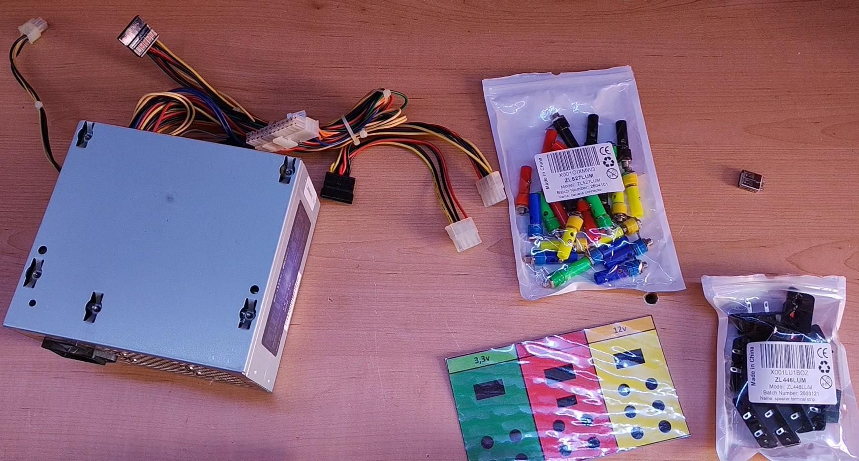
- 500W ATX PC power supply (Recycled from an old PC)
- Banana connectors (50-piece kit) (Amazon / AliExpress)
- 2-way speaker terminals (12 blocks) (Amazon / AliExpress)
- USB connector (Amazon / AliExpress)
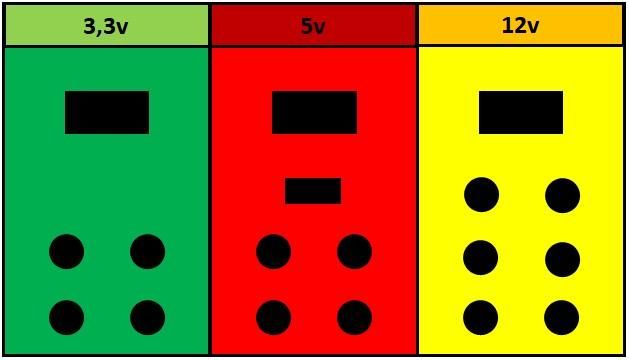
- The front panel (There’s nothing particularly complicated about it. I designed it in PowerPoint, printed it, cut it out, laminated it and finally glued it to the side of the power supply.)
Before You Grab the Screwdriver
This is where things get serious.
An ATX power supply works directly from mains electricity, and some components inside can retain dangerous amounts of energy even after it has been unplugged.
Manufacturers normally state that these units should not be opened, and I’m not going to be the one telling you otherwise.
If you decide to follow this tutorial, you do so at your own risk.
The video shows a few preliminary checks with the power supply open and powered. Do not treat these as a procedure to reproduce. Simply waiting for a while after unplugging the PSU does not prove that the capacitors have discharged.
If you don’t have the training and equipment required to safely work with this type of device, the sensible option is to use an external ATX breakout adapter and keep the enclosure closed.
The final measurements in this project were taken from the front panel with the power supply completely closed.
The 500W Sticker Doesn’t Tell the Whole Story

The power supply I used is a Brilliant Power LPK19-30E, and its label says 500W.
That sounds impressive, but it doesn’t mean I can draw 500W from any individual output.
Each voltage rail has its own maximum current rating. These power supplies normally have a label showing the available voltages, current ratings and the wire colors associated with each rail. I’ve included a photo of that label above.
The wire colors are:
- Blue: -12V. An older auxiliary or special-purpose voltage. I didn’t use it for this project.
- Black: Ground, or 0V / GND. This is the common return for the different voltage rails.
- Yellow: +12V. Typically used for the CPU, graphics card, drives and motors. The PSU I used measured around 11.25V on these wires.
- Red: +5V. Used for logic circuits and other components. I also used this rail for the USB port.
- Orange: +3.3V. Typically used by RAM and parts of the motherboard. On my front panel I marked this section in green.
- Green: PS_ON. This is the power-on signal. Connecting it to ground switches the PSU on. I left it permanently connected to a black ground wire so the PSU can be turned on using the rear switch.
- Gray: Power Good / Power OK. This signal indicates that the PSU output voltages are stable. I didn’t use it for this project.
- Purple / Violet: +5V Standby. This rail remains powered even when the PC itself is turned off. I didn’t use it for this project.
All of this makes much more sense once you open the PSU and see the bundle of wires. You can identify the different groups and start organizing them for the new outputs.
First Steps
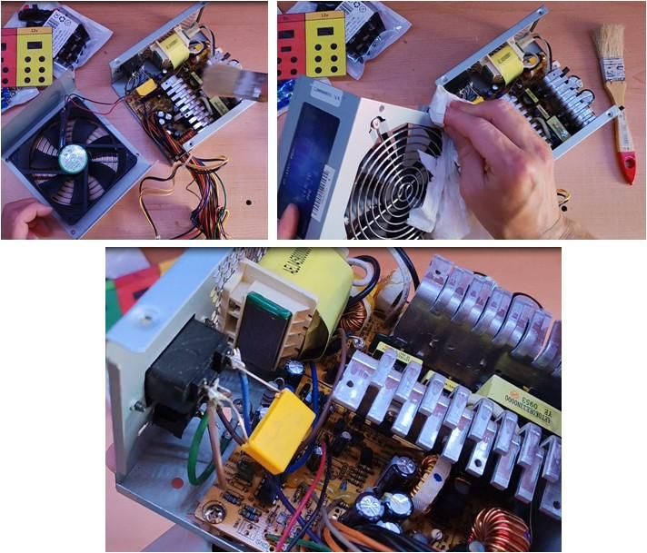

Once the cover is removed — which is simply a matter of undoing four screws — the inside of the power supply is exposed.
This is a good opportunity to remove dust and dirt. It’s also worth visually checking the capacitors for obvious signs of damage, such as bulging tops or leaked electrolyte.
I then carried out a couple of checks to make sure everything was working correctly before continuing.
Be extremely careful when handling an open, powered power supply!
Also remember that, for a standard ATX power supply to start, the green wire needs to be connected to one of the black ground wires.
Time for the Front Panel… and the Holes
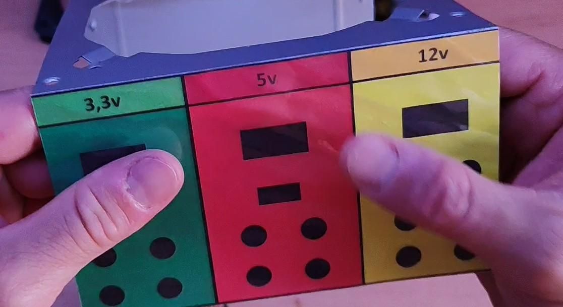
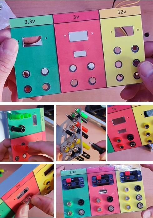
Once I had verified that the PSU was working, I removed the fan to give myself a little more room to work.
Then I glued the front panel to one side of the PSU enclosure — specifically, the side that seemed to leave the most room inside for the banana sockets and connectors.
The front panel divides the outputs into different areas, making the three voltages much easier to identify.
Next, I drilled and cut the holes for each connector and port.
In my case, I even ended up with one hole too many, so I decided to make use of it by installing another type of connector.
It wasn’t part of the original plan, but problem solved.
After drilling or cutting the metal enclosure, it’s very important to remove all the metal shavings and keep them well away from the electronics.
A tiny metal shaving might not look like much, but if it lands in the wrong place it can turn a perfectly reusable power supply into scrap almost instantly — as well as potentially giving you quite a scare.
Once the holes were finished, I installed all the connectors and got everything ready for the wiring.
Organizing the Wiring — and Making the Case Close Again
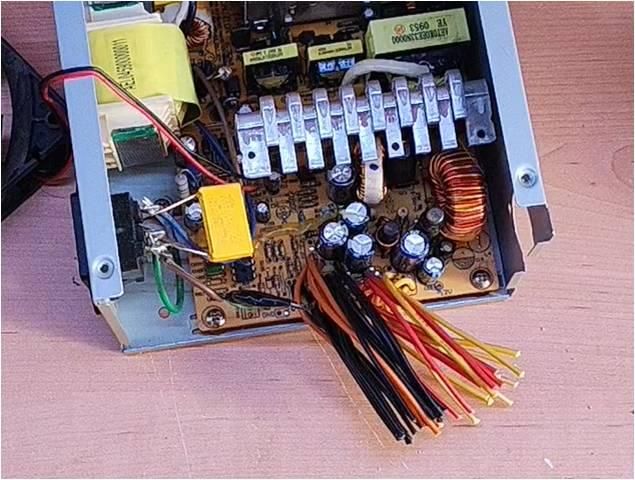

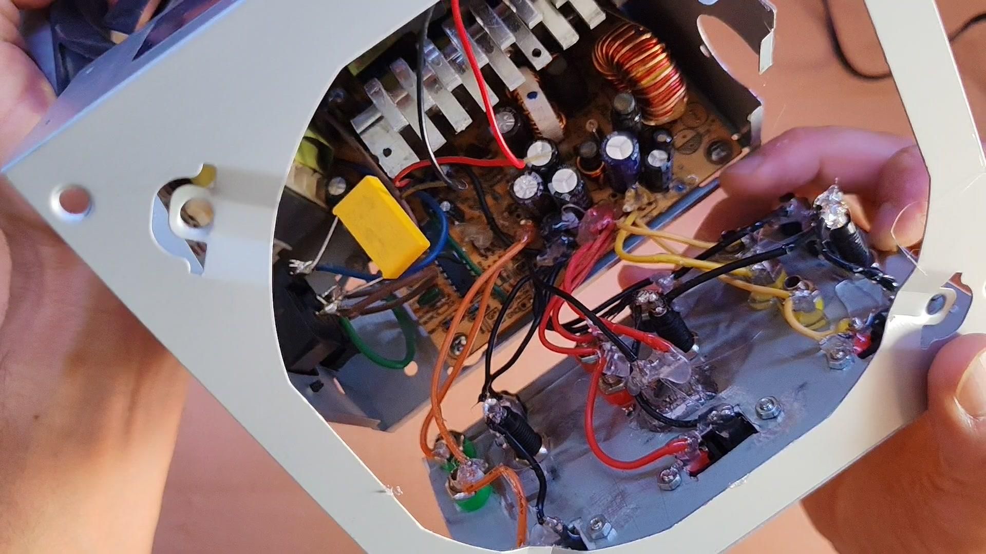
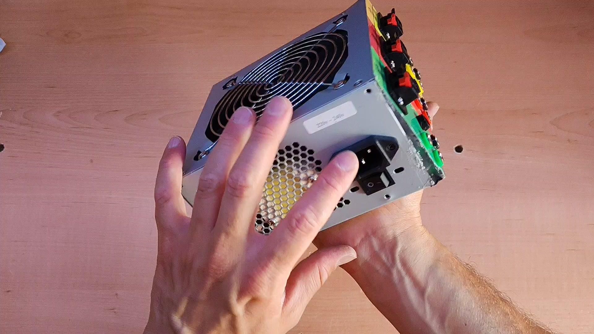
With the front panel ready, I separated the wires by voltage and routed each group to the corresponding section.
The first thing I did was connect the green PS_ON wire to one of the black ground wires. This means the PSU will switch on whenever I use the switch on the back.
Then I cut and prepared the remaining wires for the banana connectors, USB port and speaker terminals.
As a quick reminder:
- Orange wires: 3.3V
- Red wires: 5V, including the USB port
- Yellow wires: 12V — well, mine measured around 11.2–11.3V during testing, but we’ll call it 12V.
- Black wires: Ground. These can be used with any of the voltage outputs.
Finally, I didn’t need the gray, blue or purple wires for this project, so I cut them back near the board and insulated them so they couldn’t accidentally make contact with anything.
Once the connections were finished, I trimmed the remaining unused wires and insulated every unused connection and cut wire to keep everything safely isolated.
With all the wiring finished, the only thing left was to reinstall the fan and carefully close the enclosure.
Let’s See What We Actually Got
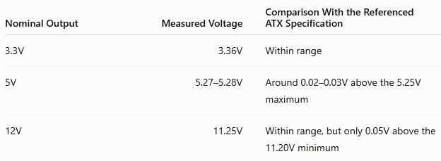

With the case completely closed, I measured the three outputs directly from the front panel.
In table enclosed, you can find the readings shown in the video.
The 3.3V output didn’t give me any surprises.
The 5V rail did. Those 5.27–5.28V readings are slightly above the 5.25V maximum specified in Intel’s ATX 3.0 guide.
The 12V output, at 11.25V, is within the same specification, although only just.
These aren’t huge differences, but I don’t want to ignore them just because the fan started spinning.
Before connecting a sensitive circuit board or trusting the USB output with anything valuable, I want to repeat the measurements under a different load and, if possible, with another multimeter.
That should tell me whether I’m just seeing an isolated reading or how the PSU actually behaves when it’s doing real work.
The Test I Actually Wanted to Do
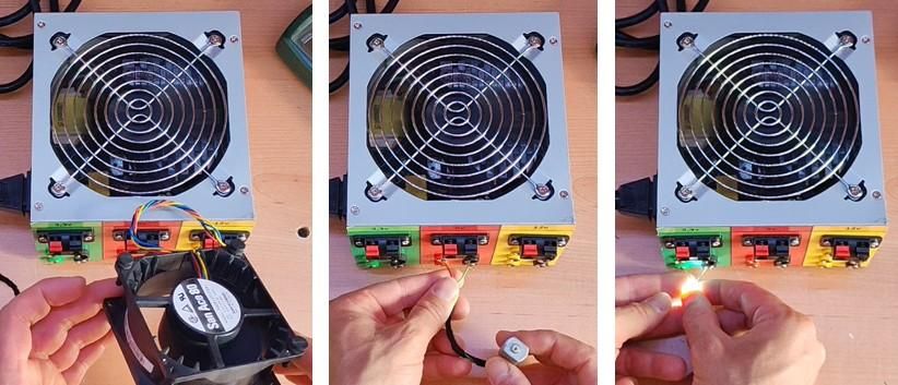
Looking at numbers is useful, but I built this power supply because I wanted to connect things to it.
During the test I used a PC fan, several small motors and an LED. All of them worked when connected to the new front-panel outputs.
That confirms that I can already use the PSU for this kind of tinkering.
What it doesn’t tell me is how much current it can reliably deliver for hours, how hot it gets, or how much each voltage drops under a serious load.
To answer those questions properly, I’d need another test measuring current, temperature, operating time and voltage under load.
So, Was It Worth It?
For me, yes.
I now have easy access to 3.3V, 5V and 12V for testing fans, small motors, LEDs and other projects that use fixed voltages.
I’ve also reused a power supply I already had without turning it into a more complicated project than I actually needed.
But I’ll use it knowing exactly what it is:
- I can’t adjust the output voltage.
- I don’t have adjustable current limiting.
For troubleshooting delicate electronics or limiting current precisely, I’ll still use a proper laboratory bench power supply.
But for spinning up a fan, testing a motor or quickly powering a simple project, this recycled ATX supply is now ready for tinkering.
Before trusting it with sensitive electronics, though, I still want to repeat those 5V and 12V measurements under load.
I hope that you enjoy it!
You can see this project in Spanish here