Tweeting Earthquake Sensor
by 4D Makers in Circuits > Electronics
501 Views, 1 Favorites, 0 Comments
Tweeting Earthquake Sensor

This project entitled, Tweeting Earthquake Sensor is a project that aims to alert the user whenever it detects tremors or earthquakes. Using a tilt switch, it will effectively measure if an earthquake vibration is occurring within the predefined timeframe.
When the alarm is triggered, it will then send a tweet using the MOTG-WiFi-ESP, notifying about the earthquake sensed.
How It Works

The sensor will determine the vibration of the surrounding and if the sensor gather enough values to state that there is an earthquake, the alarm will turn on, and the device will send tweet.
Components


OPTION 1:
gen4-uLCD35-DT
MOTG-WiFi-ESP
gen4-PA + MOTG Breakout Board
uUSB cable
OPTION 2:
gen4-uLCD35-DT
MOTG-WiFi-ESP
MOTG-Breadtooth
Bread Board
Connecting Wires
External 3.3v Power Supply
uUSB Cable
Building the Project
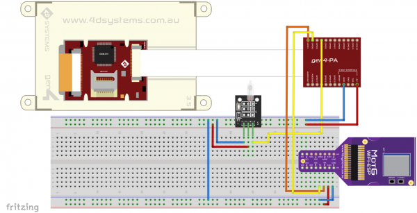

- Build the circuit as shown in the diagram. (For option 2)
- Download the project file here.
- You can download Workshop 4 IDE and the complete code for this project from our website.Open the project using Workshop 4. This project uses the ViSi Environment.You can alaso modify the properties of each widget. (As shown in Image 2)
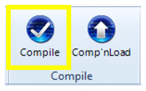
- Click on the Compile button.(This step could be skipped. However, compiling is essential for debugging purposes.) (Shown in the third image)
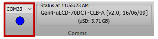
- Connect the display to the PC using μUSB-PA5 and a mini USB cable. Make sure that you are connected to the right port. Red Button indicates that the device is not connected, Blue Button indicates that the device is connected to the right port. (See Image 4)
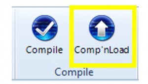
- Now click on the “Comp’nLoad” button.(Shown in Image 5)
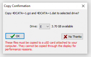
- Workshop 4 will prompt you to select a drive to copy the image files to a μSD Card. After selecting the correct drive, click OK. (As shown in image 6)
*Diagram for option 1 is to be added in future revisions.This option provides a built-in speaker from the gen4 PA+MOTG Breakout board.
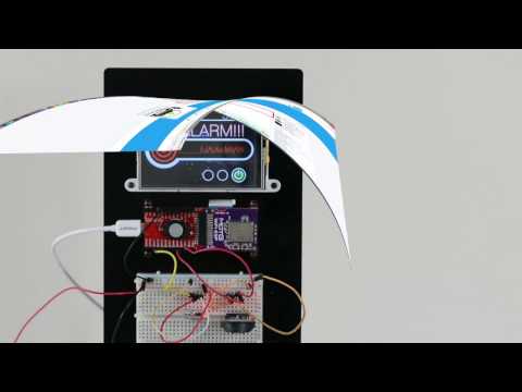
Demonstration

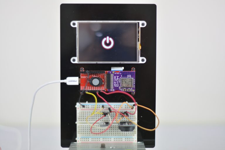
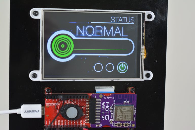

The module will prompt you to insert the μSD card.Properly unmount the μSD Card from the PC and insert it to the μSD Card slot of the display module. The image abobe must appear on your display after completing the steps.