USB Cable to Breadboard Power Supply Using a Power Bank
by TheLeftyMaker in Circuits > Tools
10263 Views, 50 Favorites, 0 Comments
USB Cable to Breadboard Power Supply Using a Power Bank


If you think that I have a bag full of old cables, you'd be wrong. Because I have two of them. But garbage they're not, and every once in a while, a hoarded cable does come in handy.
In this instructable, I'll show you how to use an old or broken USB cable to make a simple power supply for your breadboard projects. And due to the modular nature of this DIY project, you'll be able to connect different extensions to use the cable with more than just a breadboard. You'll need some soldering skills, a couple of hours of spare time, and some cheap parts and tools.
Supplies

- An old or broken USB cable - like the one you'd charge a phone with. If you're using a faulty cable, make sure it's broken only on the side which goes into your phone, not on the side which goes into the power brick or your computer.
- A pair of connectors with wires - JST connectors, in my case. These are to make the cable modular. If you're not interested in the modular aspect of this project, skip this one. - Shopping link
- Male PIN headers - Shopping link
- Breadboard - Shopping link
- A prototyping PCB - even a small piece will do. - Shopping link
- A small LED - optional, for power indication - Shopping link
- A small 1K resistor - optional, for the LED - Shopping link
- Test Hooks - optional, to use instead of the PIN headers - Shopping link
- USB Port - optional, to use instead of the PIN headers - Shopping link
- Wire strippers - because stripping wires with your teeth isn't fun
- Soldering iron
- Third hand tool (optional)
- Heat shrink tube or electrical tape - Shopping link
- Hot glue - optional, for insulation and extra durability
- Multimeter - optional, to check if your connections are okay
*These are affiliate links - I may get a small commission if you make a purchase. The price you pay stays the same, but your support helps me make more fun projects. Thanks!
Cut and Strip the USB Cable

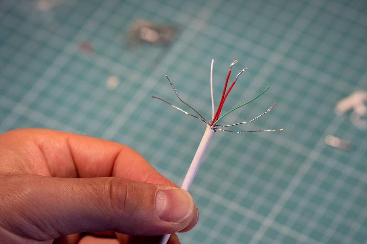


I started by cutting off the old USB-C connector from the cable. Then I removed the insulation and a few more protective layers, including the shielding made of braided wire.
Inside the cable I found a bunch of wires: one white, one green, two red, and four that had no insulation. Using a multimeter, I confirmed that the two red ones were power (+5V) and the bare wires were ground. I twisted the matching wires together, as shown in picture 3. The green and white, which normally carry data signals, are not used in this project.
I also cut a second, more basic Micro USB cable to show you what's inside (picture 4). Older, simpler USB cables usually contain just four wires: one white, one green, one red, and one black. Again, the red one is power (+5V), and the black one is ground.
I'll continue the instructable using the USB-C cable I cut first.
Solder One Side of the Connector
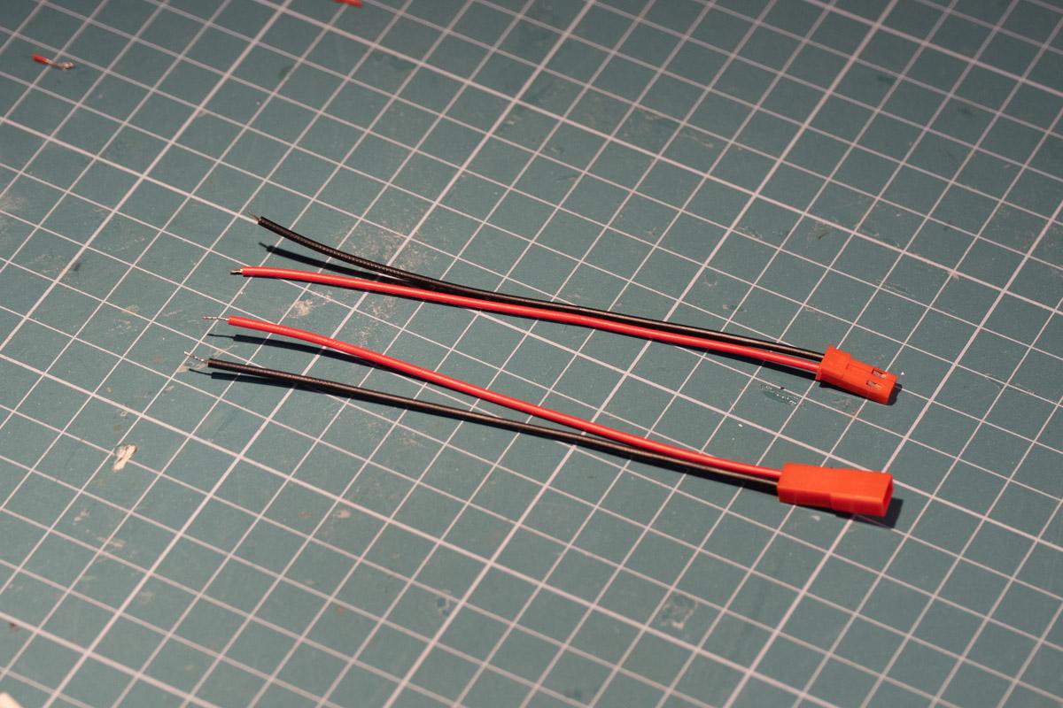
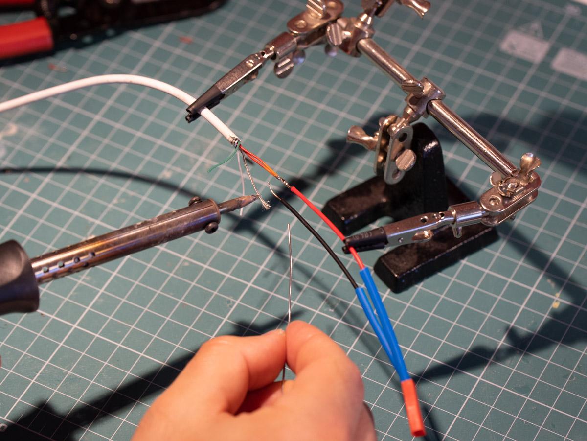
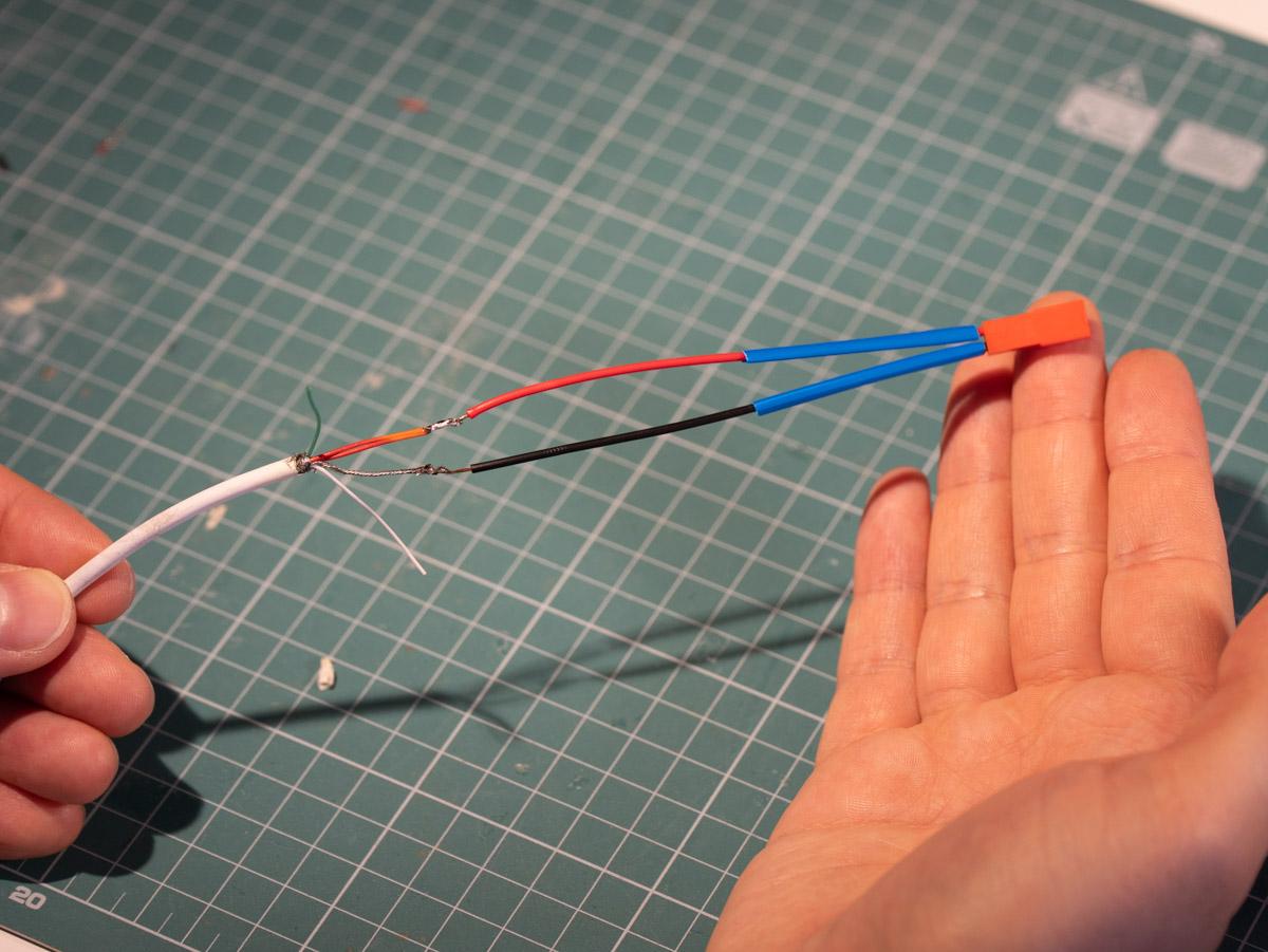


The first picture here is a close-up of the JST connector I used for this project - it's probably not the best fit for the project, but it's what I had in my parts bin. These come in sets of 10 pairs with wires pre-soldered, and the bundle costs under a dollar from China.
I soldered the USB cable to one side of the connector. I also used generous amounts of heat shrink tubing for insulation and to strengthen the connection. Don't forget to add the tubing before you solder the wires together! Of course, you can use electrical tape instead.
Solder Pin Headers to Proto Board
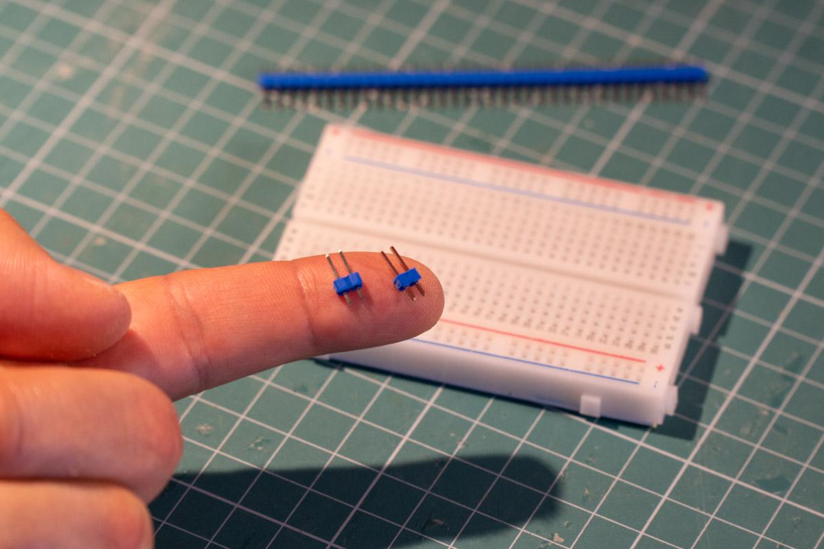
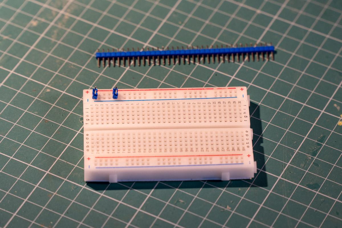


Next, I snapped off two pairs of male pin headers (picture 1) and placed them on the power bus of a breadboard (picture 2). This is to hold them in place.
After that, I soldered the pin headers to a small piece of prototyping board. The longer protoboard you see in picture 3 is there just to support the small piece. You should end up with something like what's shown in pics 4 and 5.
I suppose you can leave out the proto board entirely and connect the wires directly to the pin headers, but I think having the board will make for a stronger connection. It also allows an LED to be added, as shown in the next step.
Solder the LED


This step is optional and tricky, but I wanted to have an indication for when power is provided. I'm using a standard 3mm LED and a 1Kohm resistor - and I had to get creative to fit them all in the tight space I had.
As you can see, the resistor is on the bottom side, between the headers. A 1/4W resistor should be just the right size to fit.
The LED is on the top side. One of its legs is connected to the resistor from the bottom side, while the other leg connects to the pin header. It's hard to explain this all in text, so I hope the diagram (picture 4) and close-ups will help you figure out what's going on. Apologies for the state of my fingernails.
Solder the Other Side of the Connector
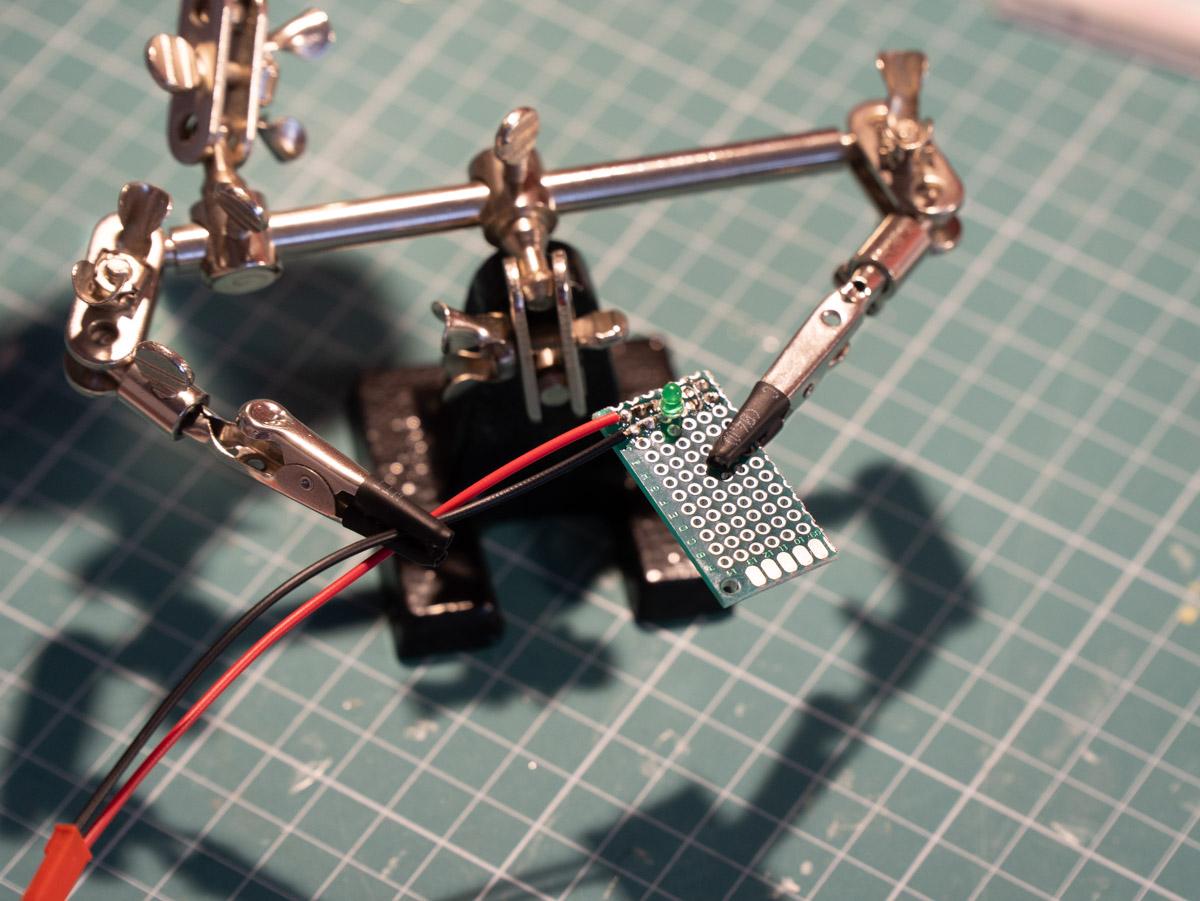
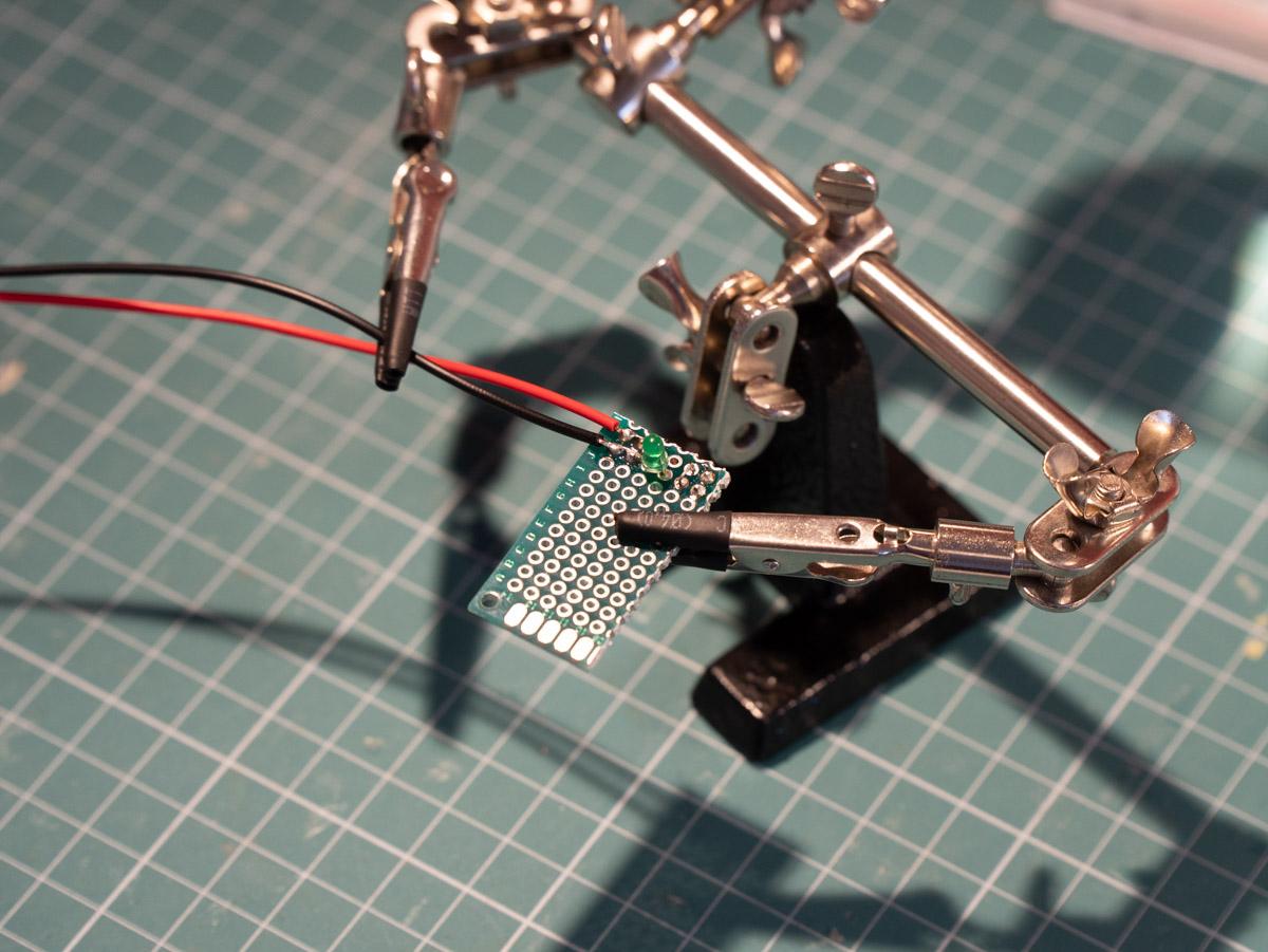
Here you see a pair of helping hands holding the piece of proto board and the cables of the connector in place while I solder them. Make sure you don't mix up the black and red wire.
Trimming the Board, Adding Hot Glue for Strength
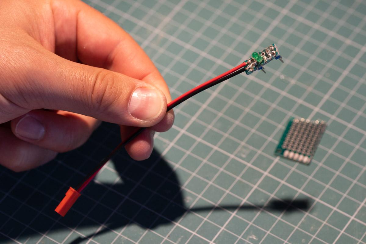
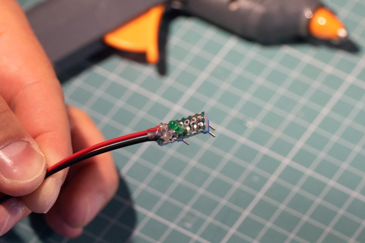
After the wires were soldered, I snapped off the excess piece of proto board and sanded down the sides to remove all the rough edges. After that, I added a few drops of hot glue around the point where the wires were soldered to make the connection stronger.
It Works!

As expected, the cable works! Here it is connected to a power bank and is providing 5V to the breadboard where I have three LEDs connected in parallel. But that's not the only use for this cable...
Additional Modules You Can Make
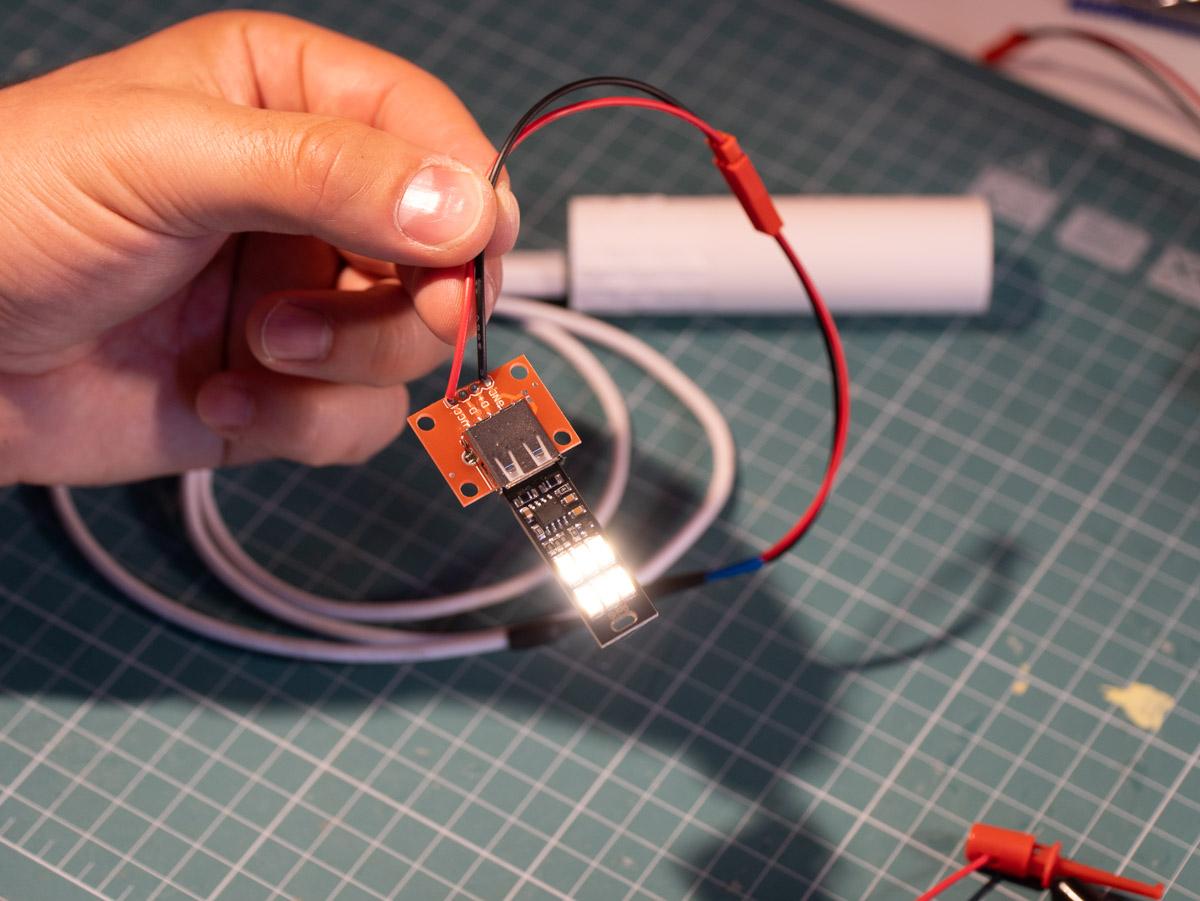
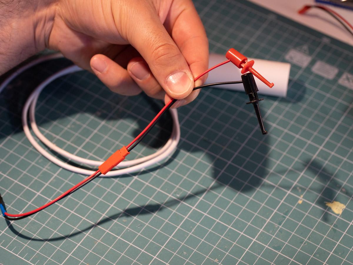
Thanks to the JST connector, we can swap the breadboard module with a different one. For example, I made a module with a full-sized USB port, turning the cable into a USB extender (without the data connectivity, obviously). I've connected a small USB flashlight for demonstration's sake.
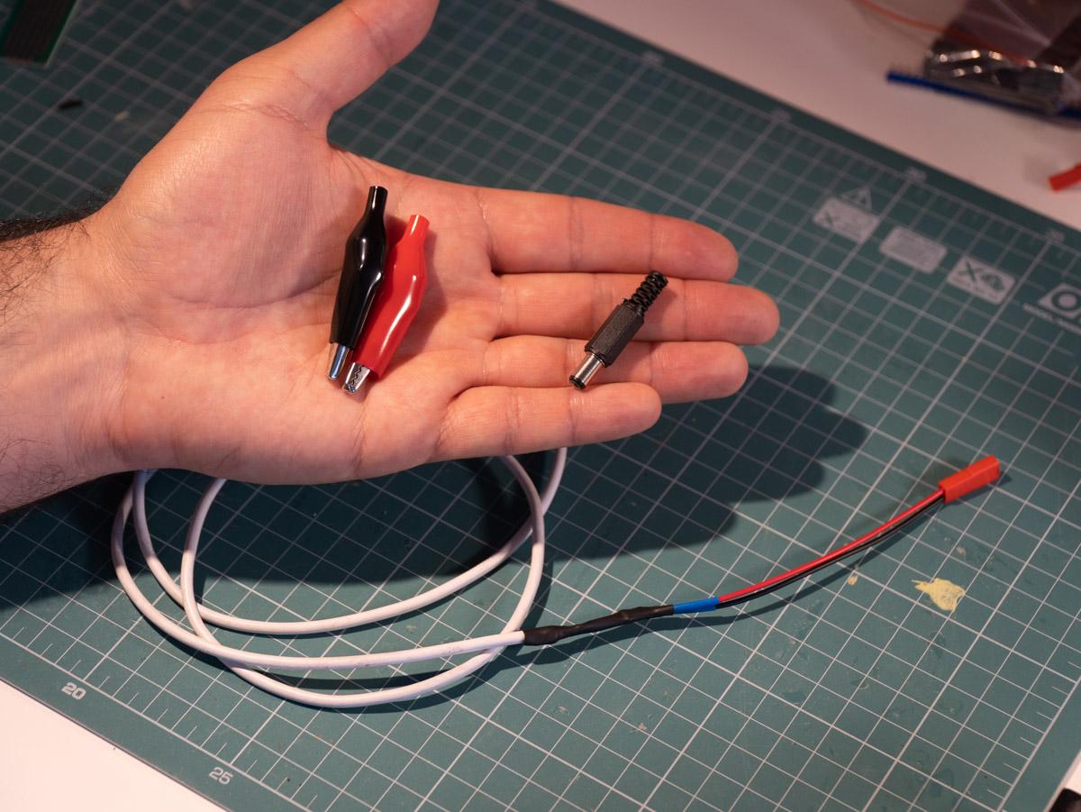
Another option is to connect a pair of test hooks, which you can connect directly to things like motors or lights. A barrel jack or a pair of alligator clips are also among the possible extensions you can make, depending on your needs.
You can check out my YouTube channel where I post project build videos and tutorials. You can also follow me on Instagram where I post projects I'm working on and bits of inspiration.