USB Desk Lamp KS3 Design Technology Projects
609 Views, 1 Favorites, 0 Comments
USB Desk Lamp KS3 Design Technology Projects

These projects have been designed by year 7 and 8 pupils in Milford Haven School in Pembrokeshire (West Wales). I gave them a brief to design a lamp that could be make by a hobbyist and shared using CC or Open Source license.
I have uploaded this project as an example but if you search my profile you should find more that the pupils have created. We would welcome any feedback on the ideas or the way we have communicated them. For this creation you will need some basic hand tools, the only thing that might cause an issue is the spot welded steel legs, I've tried to think of an alternative method; if someone has any ideas please reach out!
Kind regards.
Secondary School Design Technology teacher.
Supplies


You will need:
- Eye protection
- 82mm hole saw and battery drill
- Spot welder
- Soldering equipment (iron, helping hands, heat gun, extractor etc)
- Ultrabright white LED *you could sub for a colour changing LED
- 150ohm resistor
- 1.6mm and 5.2mm Heat shrink tubing
- Bead maker drill attachment (use in a pillar drill if possible)
- Junior hacksaw
- USB wire (you can recycle one -if you do make sure you strip and cut away all the cables apart from the red and black).
- 500mm welding rod cut into 2x250mm lengths.
- Spot welder* alternative method possible.
- Printable A4 acetate
- Drawing pins
Prepare LED for Soldering


Identify the Anode (+) and Cathode (-) legs of your LED, the long should be the Anode, there might be a flat side on the body of the LED that indicates the Cathode. Cut the legs shorter at an angle to make sure the Anode stays longer. Use your soldering iron to quickly 'tin' the legs of the LED (be careful not to overheat the LED), you only need a small amount of solder, also tin the ends of your USB cable. Make sure you haven't got too much bare metal exposed (5mm max).
Soldering the Wires and Insulating With Heat Shrink Tubing


It is really important that you insulate the conductors properly, a 'dead short' between positive and neagtive ends of the USB wire will trip out your USB PSU. Follow these instructions very clearly and if you are not sure ask a competent person.
- You will need to cut about 10mm of 1.6mm Heat Shrink Sleeving, slide it onto the neagtive (Black) wire and make sure it stays away from heat for a minute...
- You should have tinned (coated in solder) your shortened LED legs and the wire ends. Identify the Positive (Anode leg) and the Negative (Cathode leg). The black wire is going to be soldered directly onto the short cathode leg. Hold the LED in some way (helping hands/mini vice) and touch your soldering iron to the wires as they are held together- the solder on each part should melt and form a good connection- be quick, LEDs don't like heat!
- Now take the heat shrink that is trapped on the black wire and slide it down to cover all bare metal, use the hot air gun to shrink the tube so it stays in place. THIS BIT IS CRITICAL - ensure no bare wire is showing on the negative side of the circuit.
- Find your 150 ohm resistor (Brown/Green/Brown), cut it's legs a little shorter, it hasn't got a + or - (non-polarised) so you can put either end to the red wire and the other to the LED.
- Test your circuit now (before you put the big heat shrink on). If it doesn't work check a different power supply (in school I use a USB power bank) also check you haven't cut the LED legs incorrectly, the cathode side also has the flat section on the LED body remember and that should be going to the Balck wire.
- Once you know it works you can put the bigger heat shrink over the top and set it in place using the hot air gun, use just enough heat to shrink the tube, don't go crazy!
- Check it still works.
Spot Weld Legs


Measure and cut 2 x 250mm long pieces of welding rod 3.2mm diameter rod works well. Mark the centres of the metal with a sharpie. Use leather gloves to hold the metal and spot weld ensuring the marks line up and the legs are at 90 degrees to each other. Be careful, reduce the current on your spot welder and experiment on some scrap as it is very easy to melt through the rod. Thicker rod is harder to bend, see how you get on.
Making the Leg Support and Attaching the Feet


Use the hole saw to cut a 40mm diameter disc out of pine (20mm thick is good), mark out a cross that will be cut half way into the timber as shown, tenon saw and chisel it out as shown. Now take your spot welded cross and test it in the recess you have created mark the position of the 4 bends you will need to make using pliers to make the lamp stand upright. Bend the legs to equal angles or the lamp will be unstable. Next use the bead maker drill attachment to make 4 wooden spherical feet, drill these out to the same size as the welding rod legs *try not to drill right through so that the metal won't scratch the surface it is put on. Finally hot glue gun the legs into the slotted holder and the holder to the wooden base circle.
Create the Acetate Lamp Image


This part of the project can be done on any graphics program that will let you manipulate a picture and add text. I have shown Google Drawings as GAFe is our native environment for pupils work, it is accessed through Drive and saves automatically.
- Click 'Create' and look for Google Drawings.
- Click File and scroll down to 'Page Setup', click 'custom' and in cm units enter 29 and 21 (approx A4 landscape).
- Now create your image, I have refined my search to look for 'Large' images and my beach picture is 1500x1000 pixels (for good resolution). You can import any images, make a collage of your favourite band etc- fill the page.
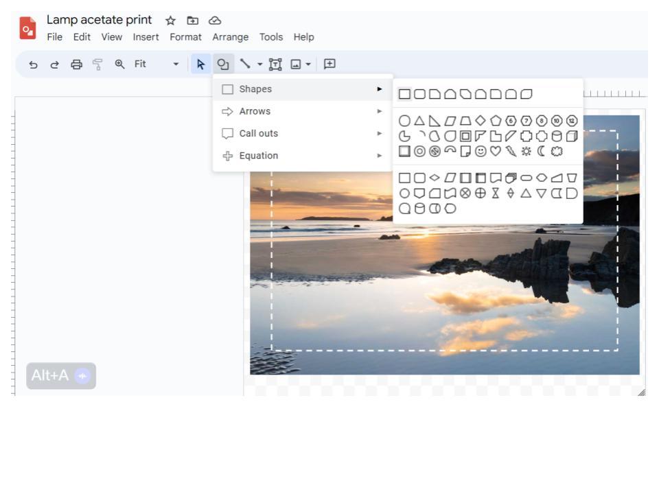
- Now create a rectange, make it have transparent fill and a white dashed line.
- Click the 'Format' button and find 'Format Options' when it opens the command box choose 'size and position' here you need to enter some importand details outlined in the next step.
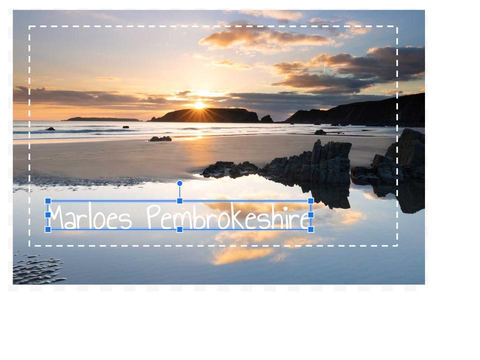
- The hole cutter I use makes a disc with an 8cm Diameter, we need the image to wrap perfectly around the disc so we must calculate the Circumference. Use pi x diameter (3.14x8 = 25.12cm) this is the width of your image, the height can be whatever you find aesthetically pleasing. Reposition your picture so you have a decent 'bleed' (image overlapping the dotted line you will cut).
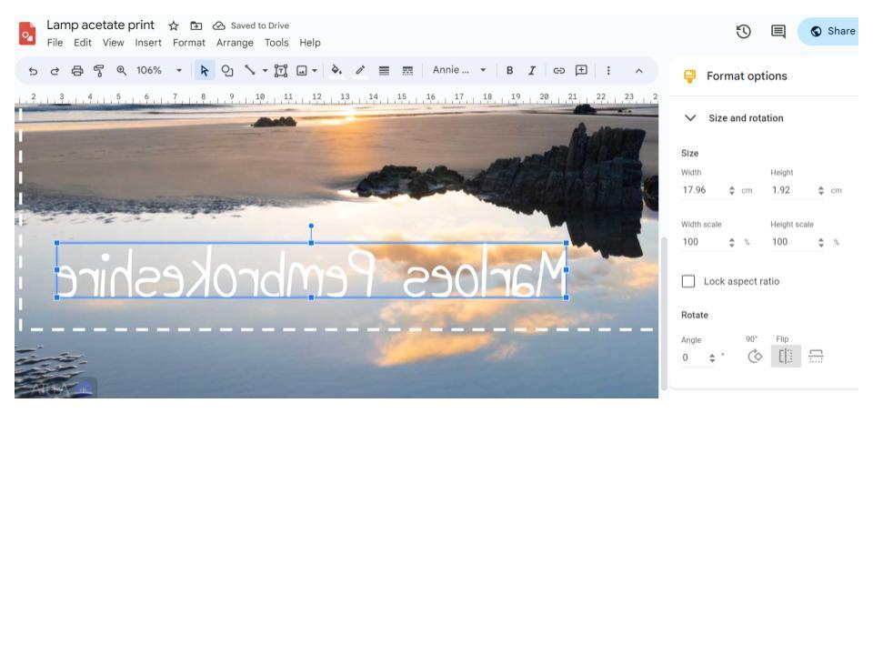
- If you want to add words make sure you use 'Word Art' as you will need to flip the type on the vertical axis before you print it.
- Print your picture at the highest quality settings you can, either straight onto printable acetate or paper then across. Flipping the image should mean that your gloss layer isfacing the right way and the colours are more vivid.
- I have included the picture of Marloes Sands in Pembrokeshire, the sun is in the perfect place to give a lovely effect when the lamp turns on and it's also my favourite local beach! You will probably want your own image.