USB Powered Coin Battery Dummy
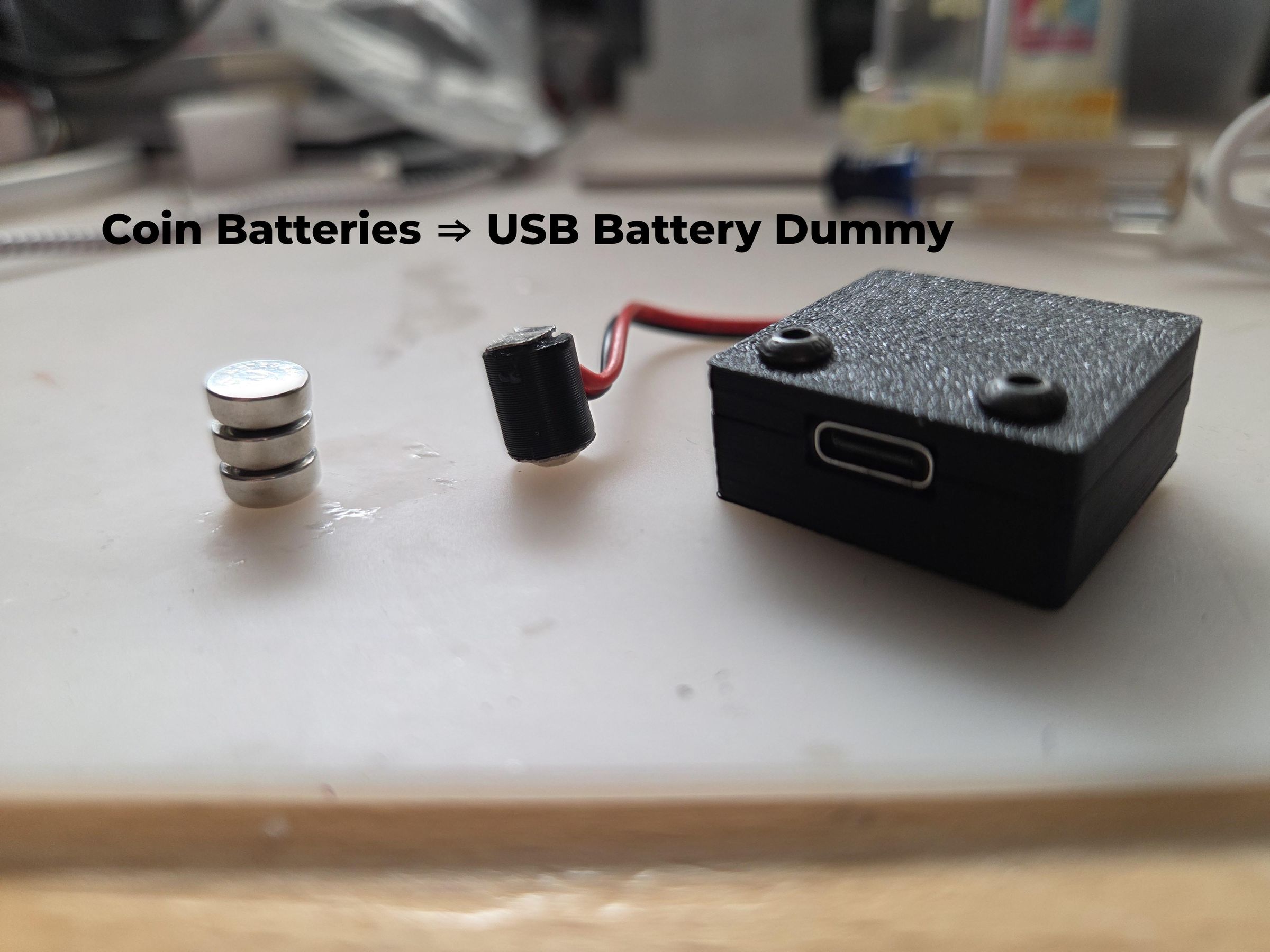
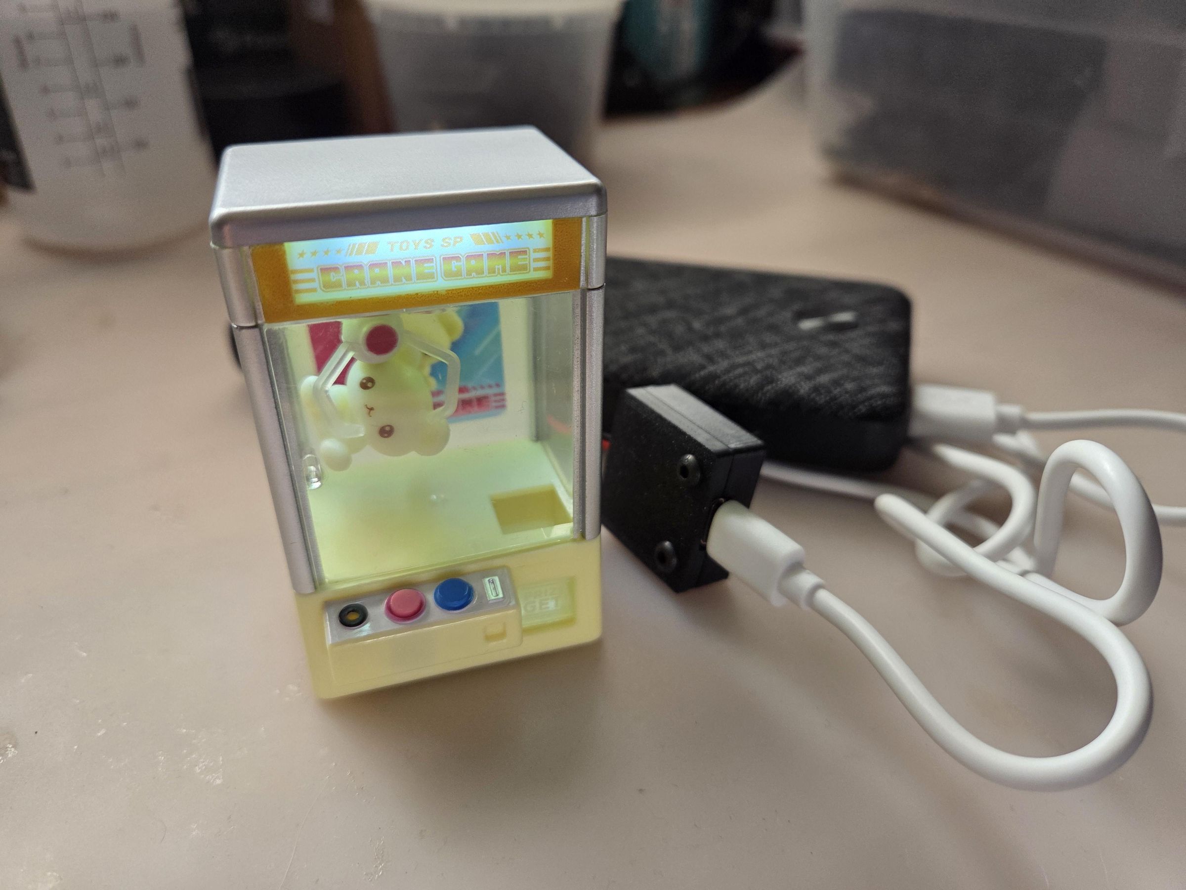
Want to keep that button coin cell battery trinket / toy / whatever always on and not have to keep buying new batteries or directly soldering wires into the battery compartment? Use this easy to make coin battery dummy that powers your device off USB.
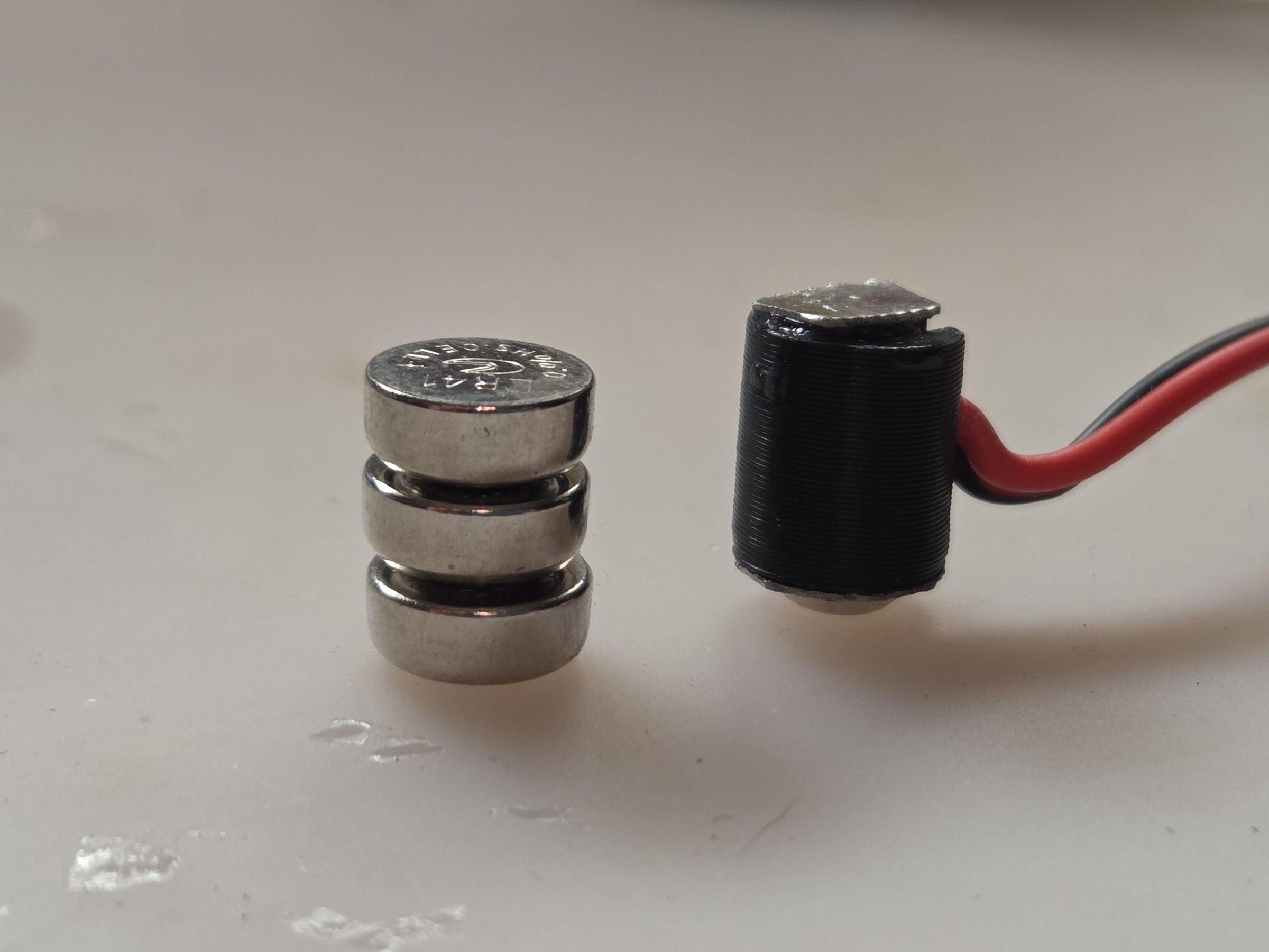
I wanted to keep a toy on my desk to be always on. The toy is powered by three LR41 button cell batteries. I do not want to keep buying batteries so figure why not power the toy off USB. Quick google search shows a store selling stacked dummy buttons for some $$$ (last I checked was over $50 for my needs). Figure, I give it a go to make my own and turns out fairly easy to do with the right equipment.
Supplies
- Tools
- Sheet metal cutter
- 3D printer
- Soldering iron
- Materials
- Small pieces of metal that you can solder to, I used battery spring plates like these (Amazon)
- USB-C female breakout board (Amazon)
- M3 3x5x4 heat set insert (Amazon)
- M3 x 10mm screws
- Wire 24awg
- 1N4148 diodes (or pretty much any small diodes)
- Printer filament
- Super glue / cyanoacrylate
- Metal file
Print 3D Parts
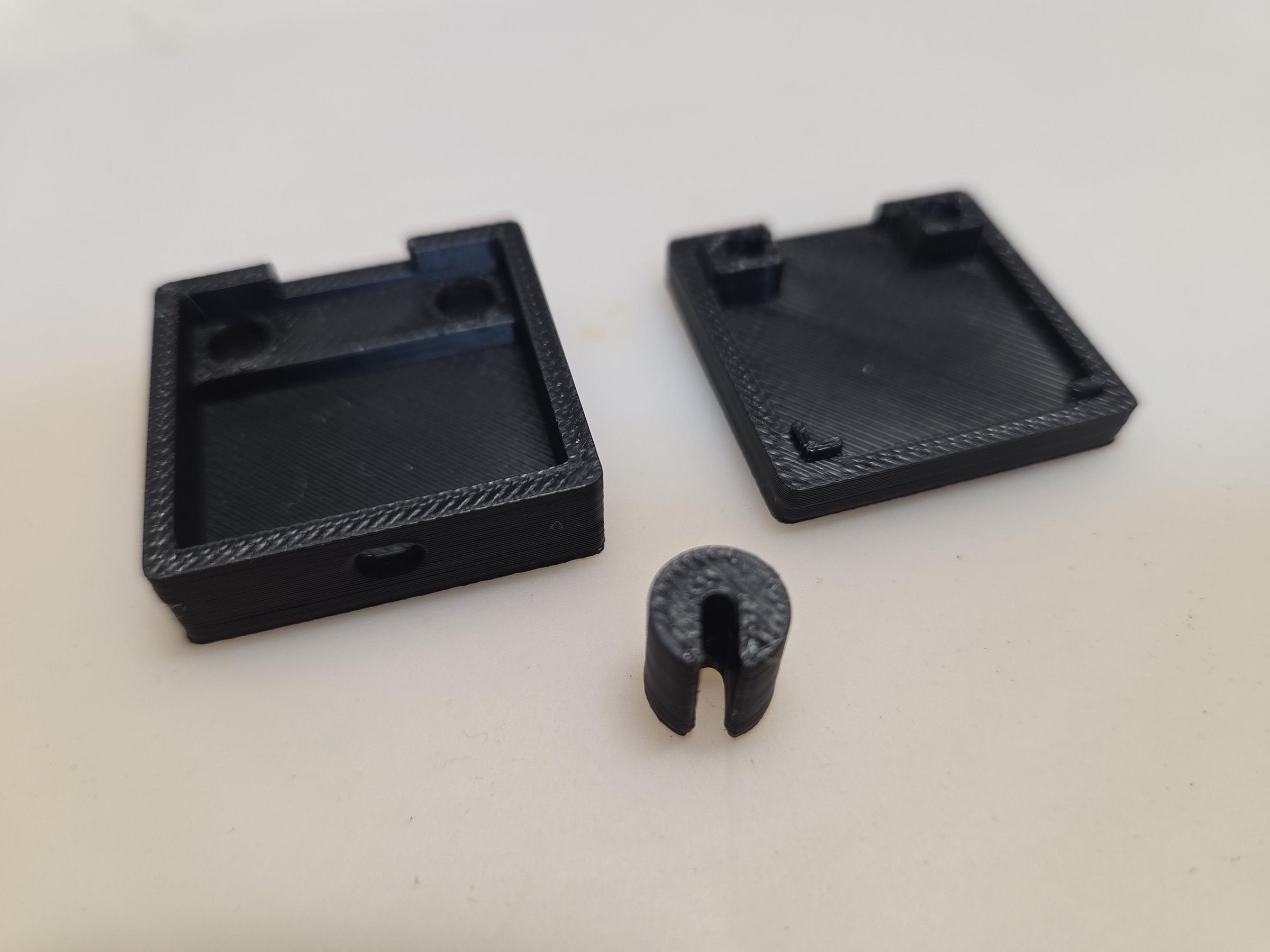
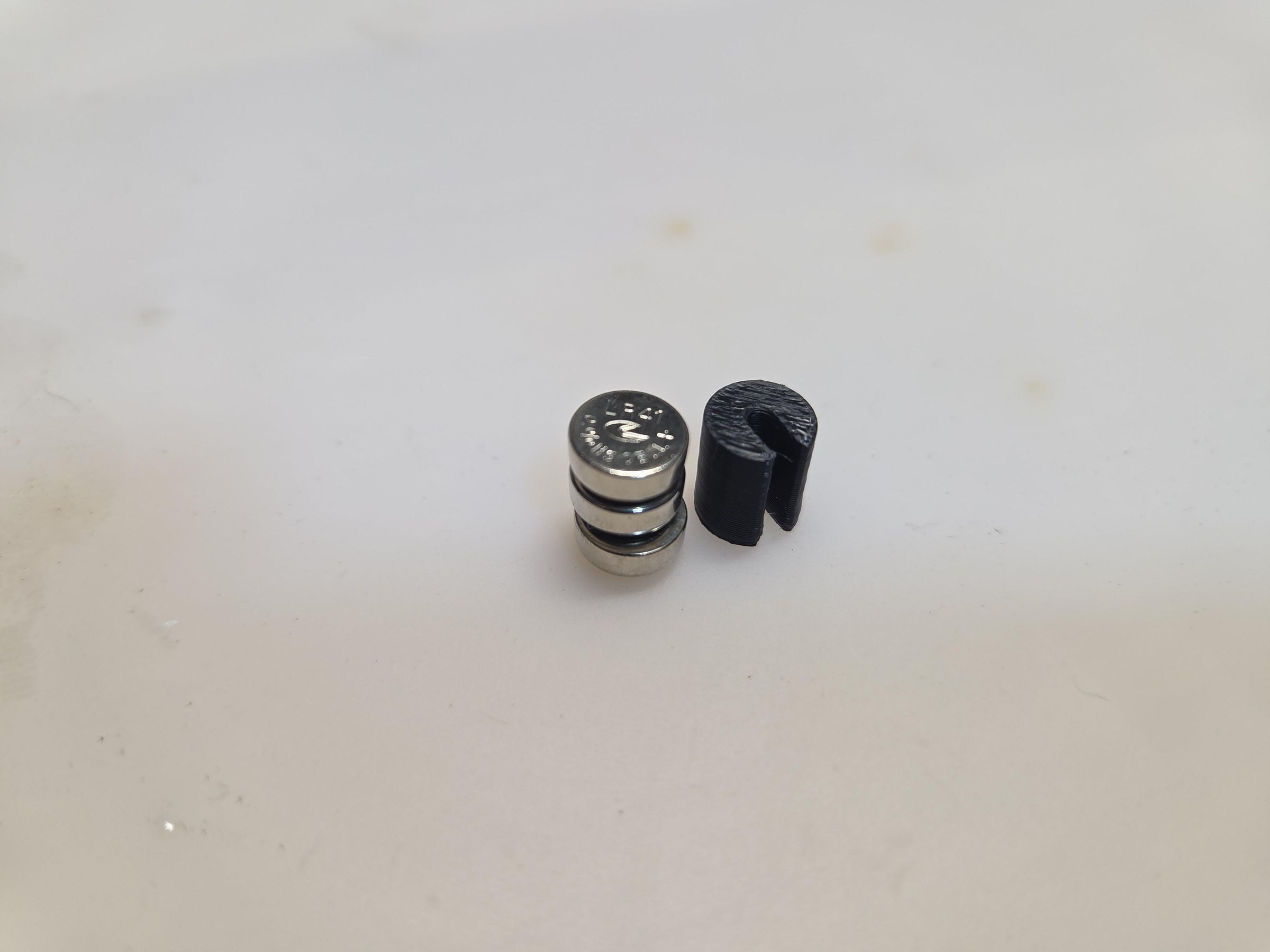
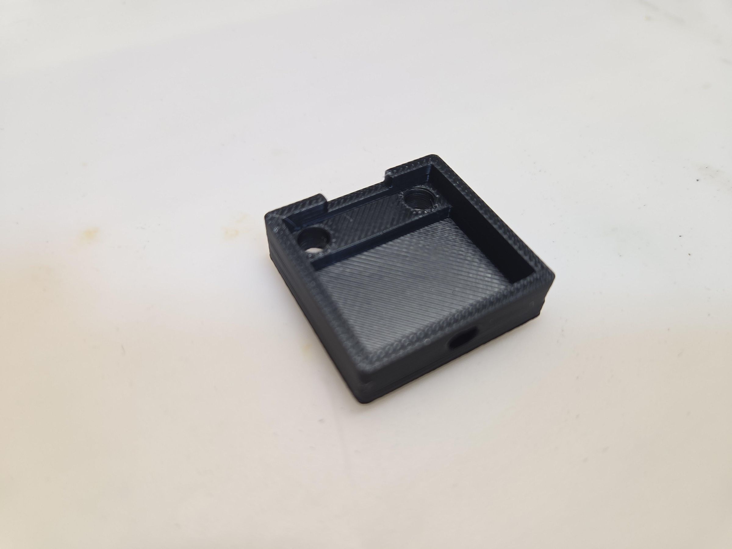
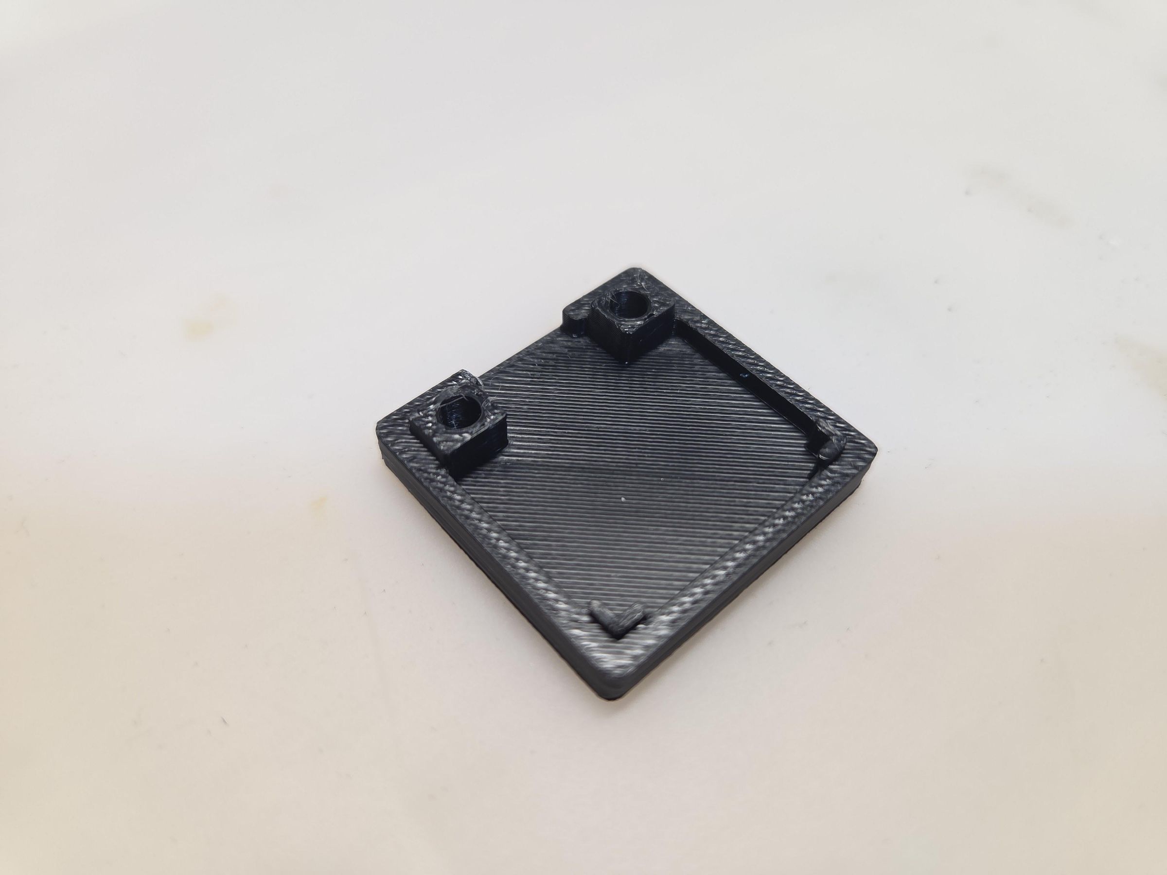
Print the attached STLs for the dummy battery and case top & bottom.
Prep USB-C Module Case
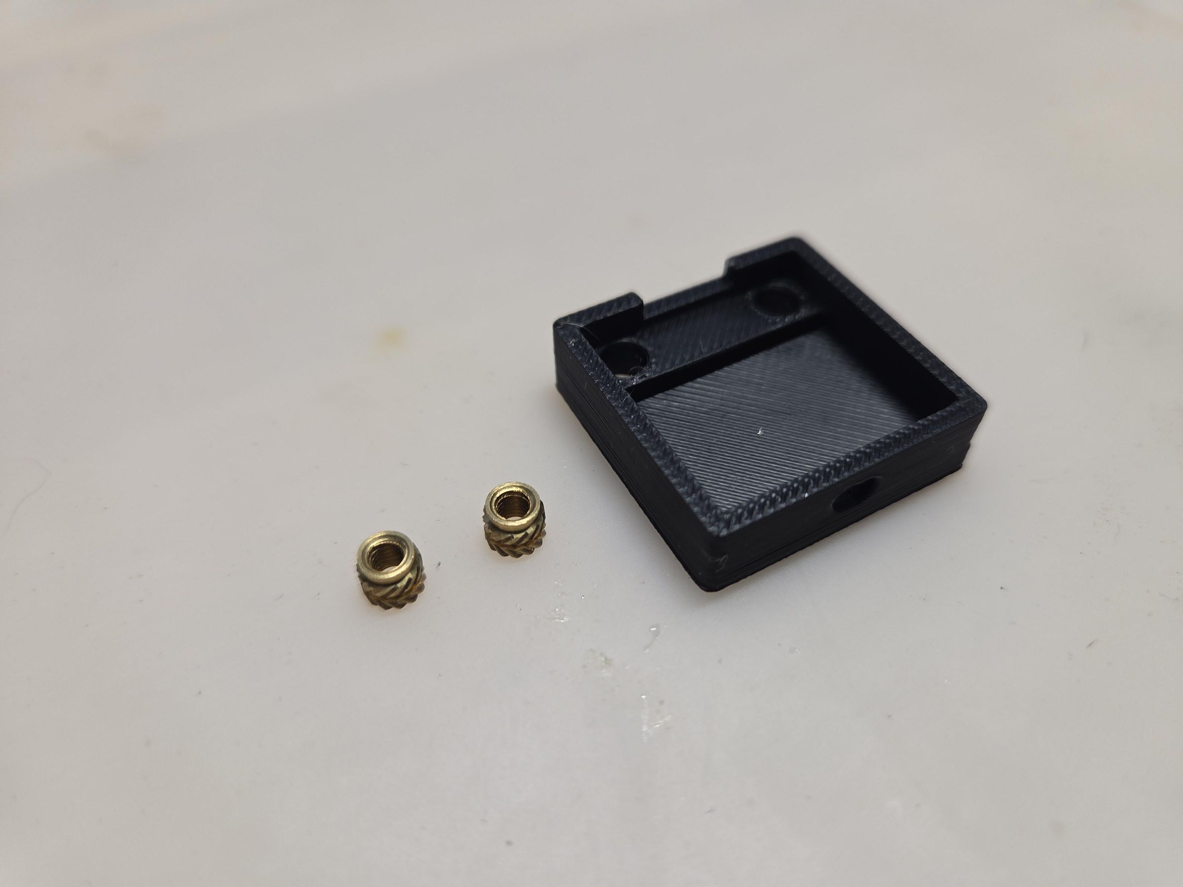
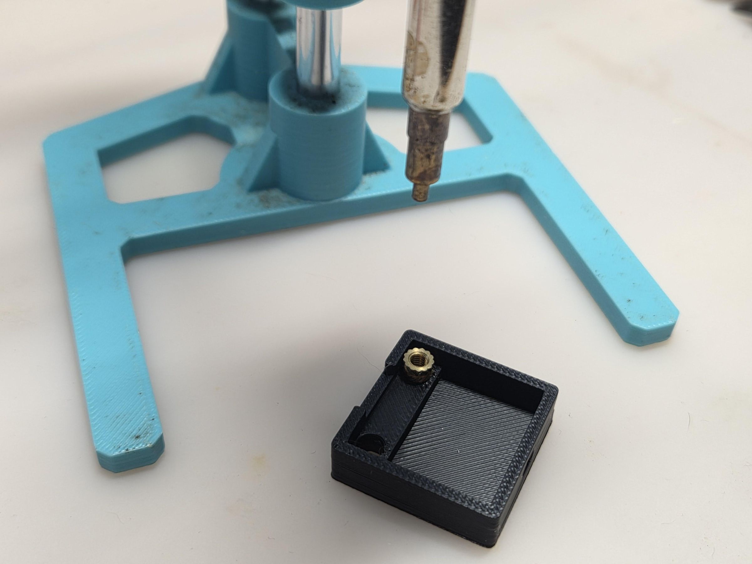
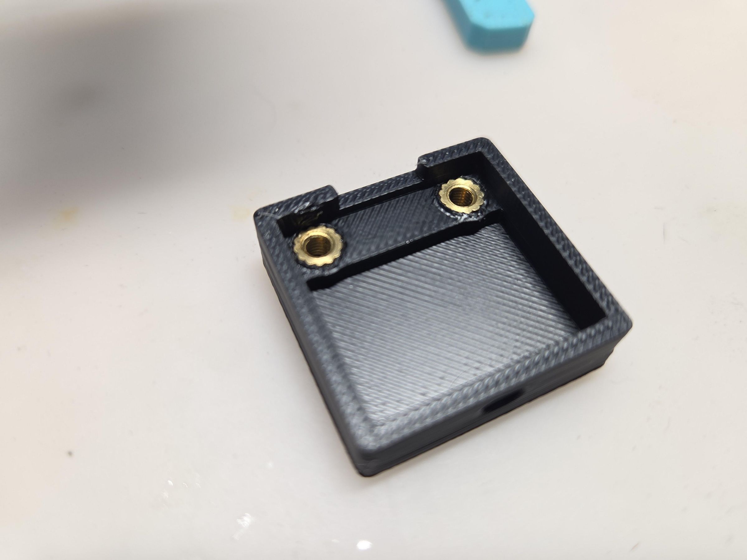
I went the route of using heat set inserts, not necessary, I just like using them. Use your soldering iron to press the inserts into the holes in the bottom of the case.
Alternatively, you could modify the case model to make the bottom holes smaller and let the screw self-thread when securing the case.
Snip Terminals to Size
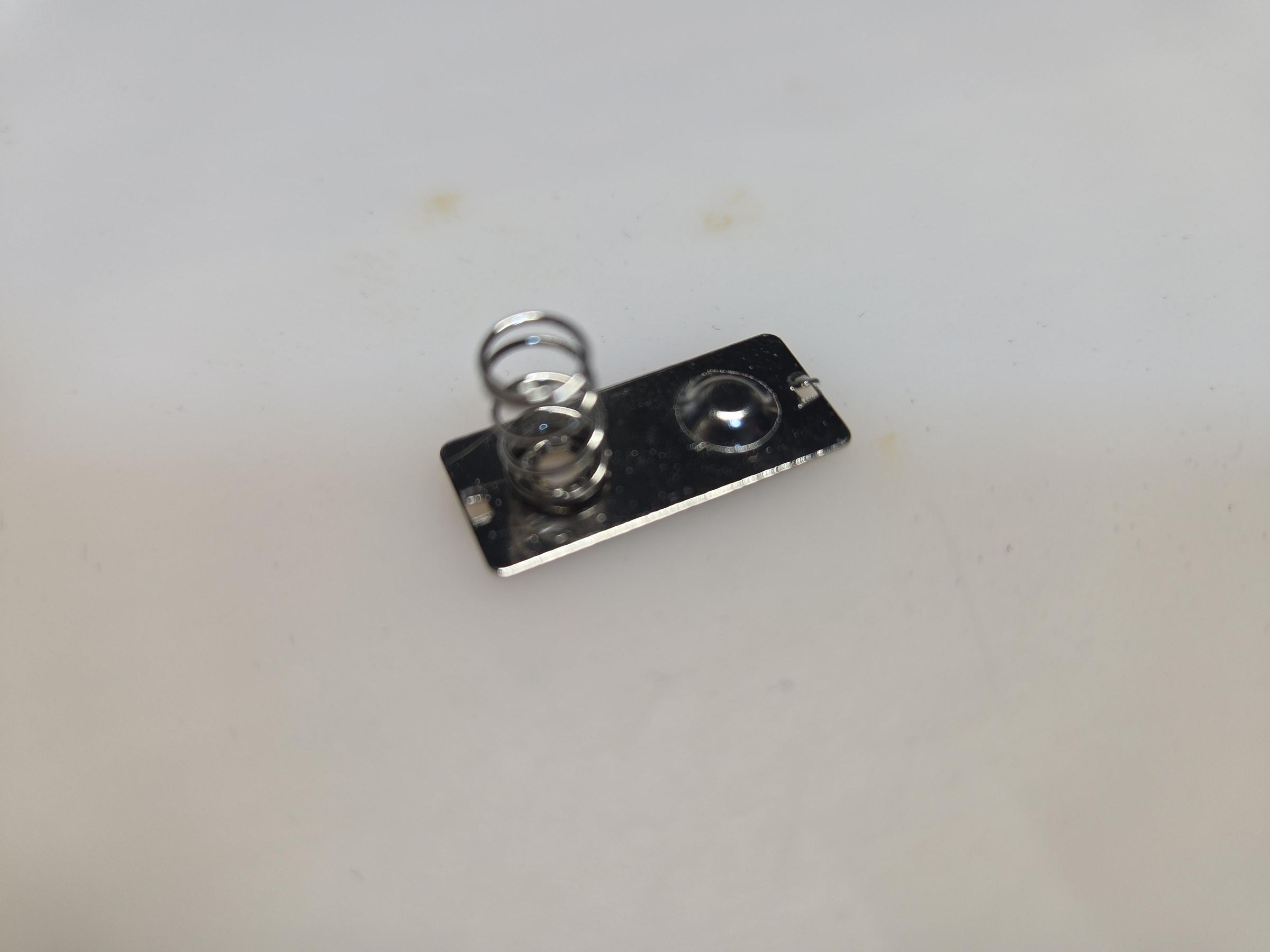
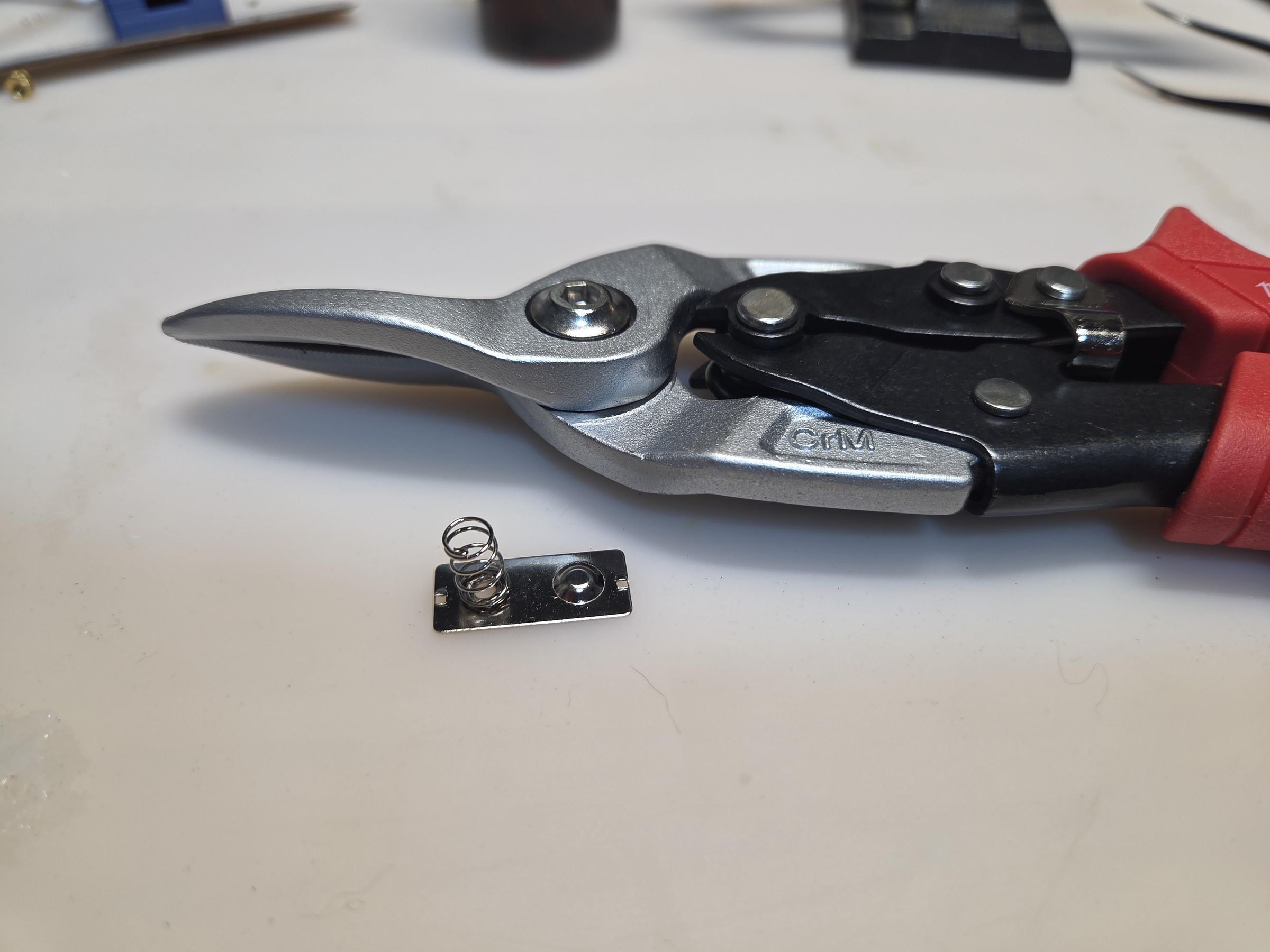
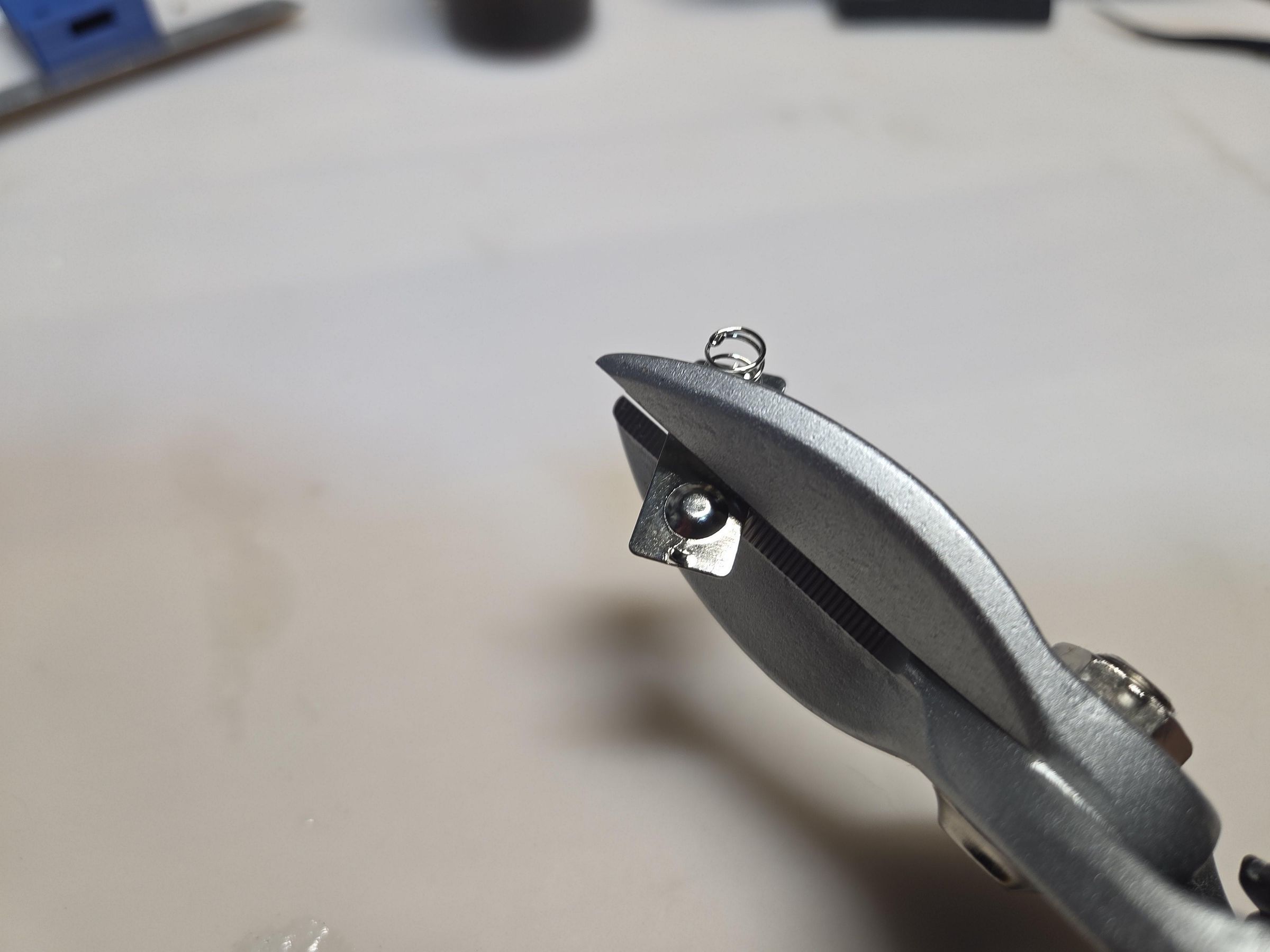
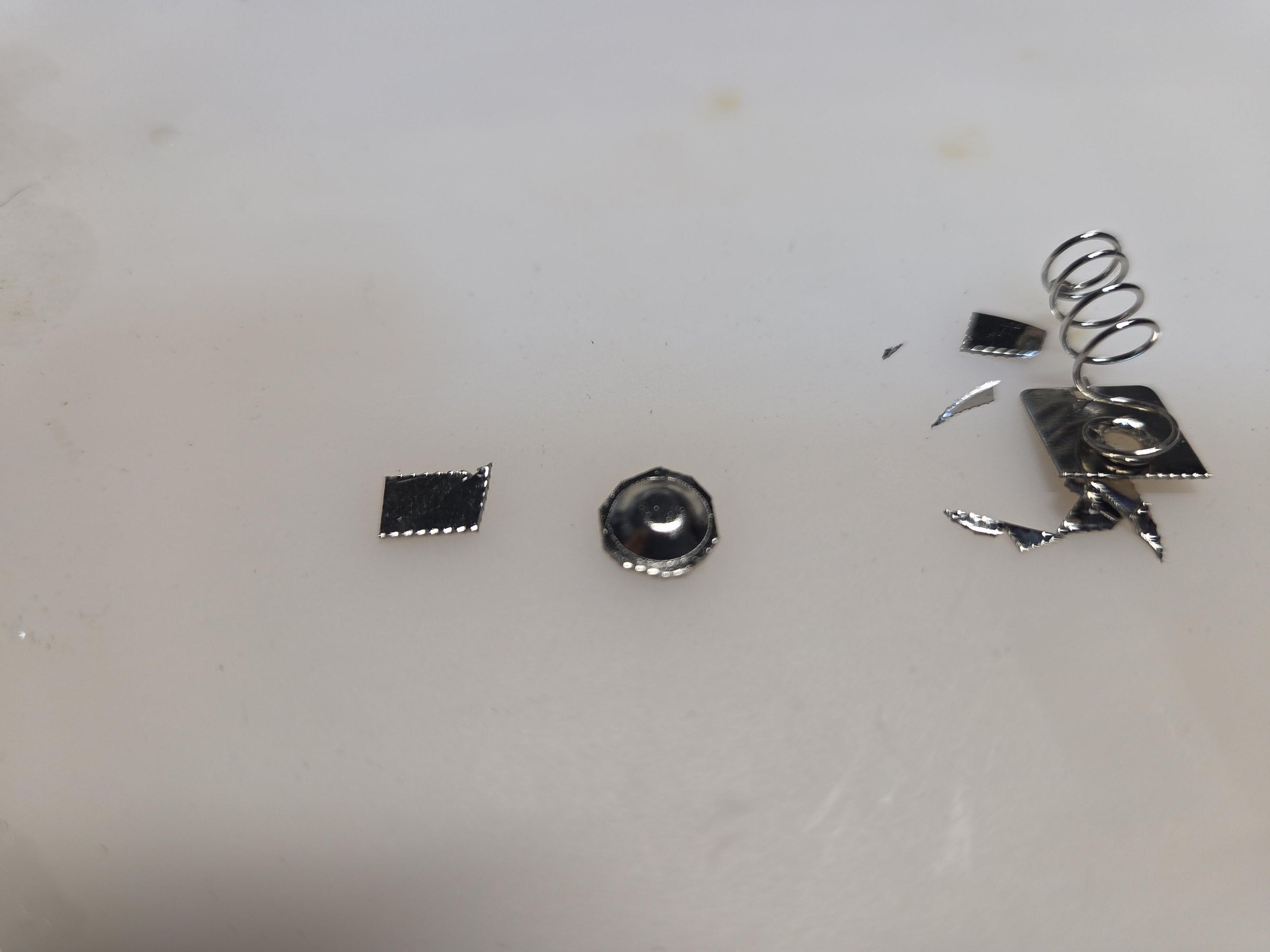
You can do this step while you wait for the parts to print.
I used battery spring plates as I had leftovers from fixing another toy that had its battery leak and corrode the battery compartment. You can use any metal that you can solder to. The attached dummy model accounts for the spring plate bump to be the exact size of 3 stacked batteries but I think you can still use as is since the spring in most toy battery compartments are long as is. If you really want exact size then you will have to resize the height of the model in your slicer.
Cut out the circular bump part.
Cut out another piece about the same size as the circular piece you just cut with the left over plate.
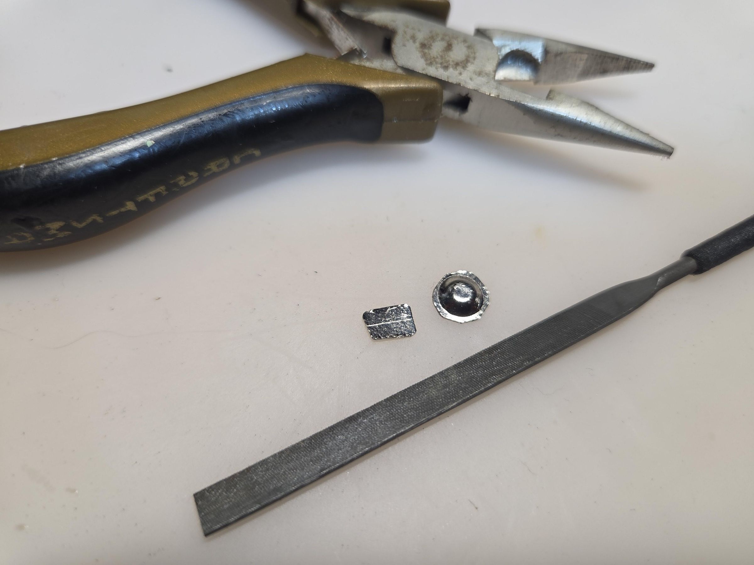
File the edges round since they could be sharp.
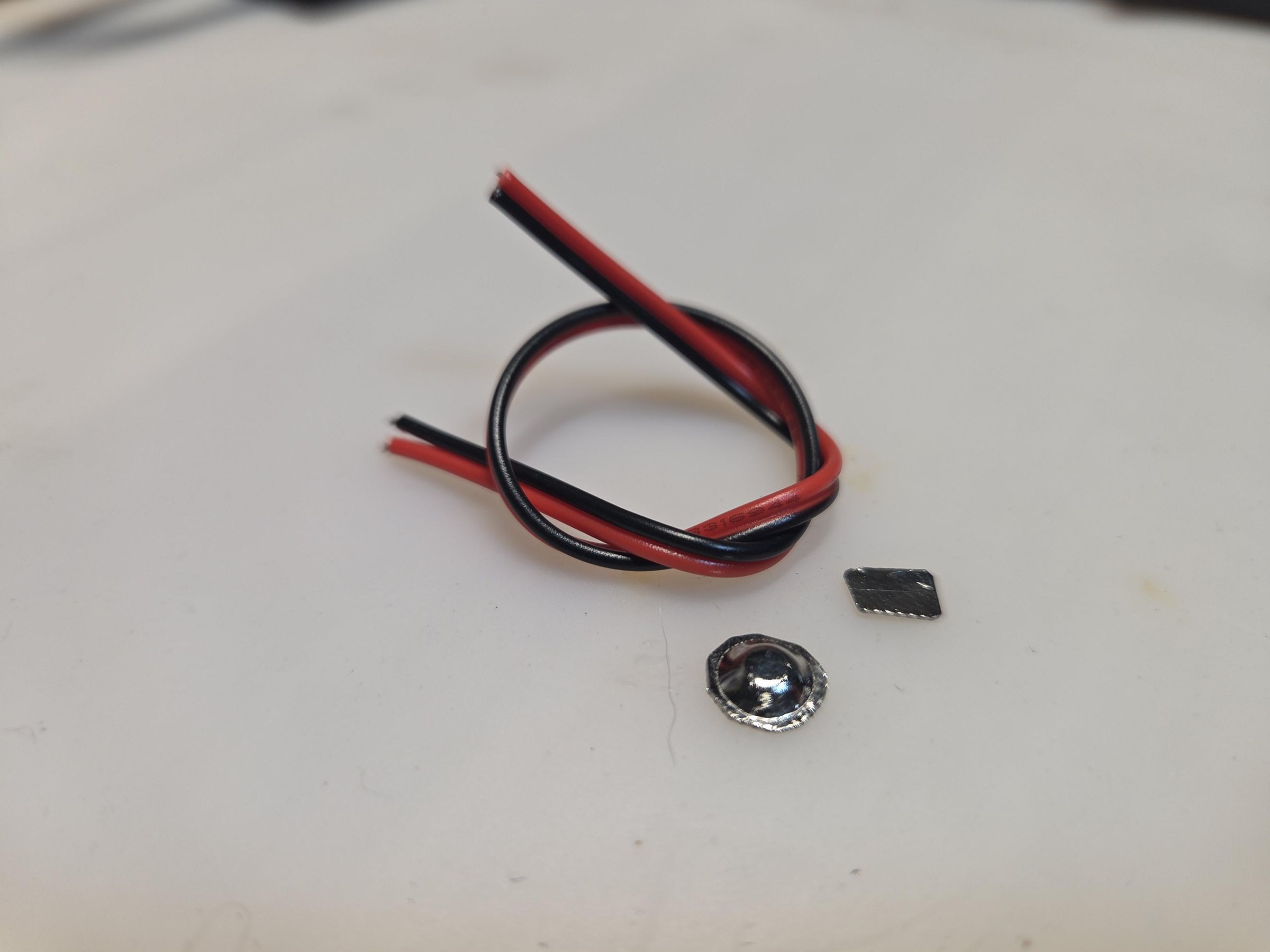
You now have a bump terminal and a flat terminal plate.
Attach Wire to Terminals
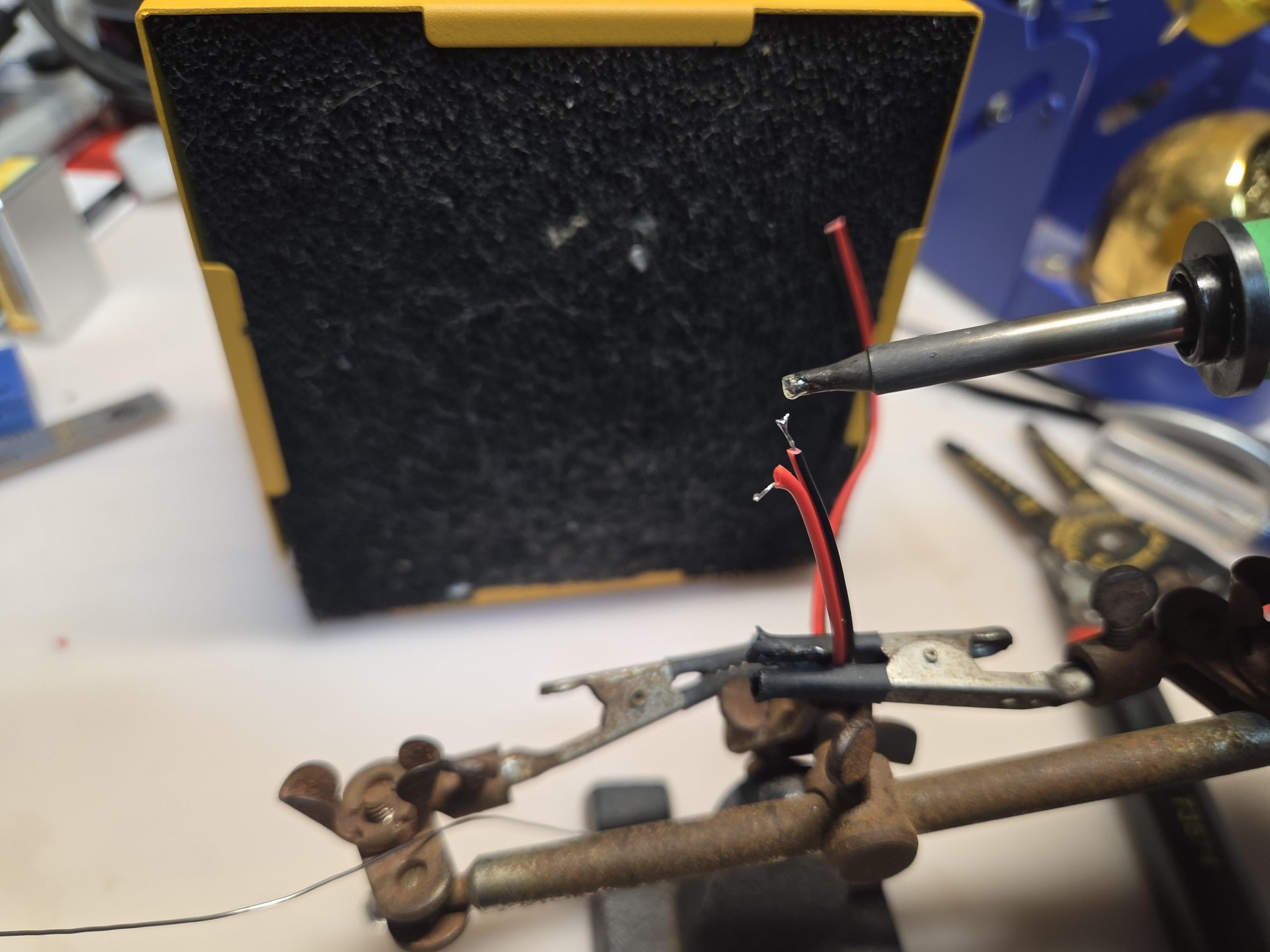
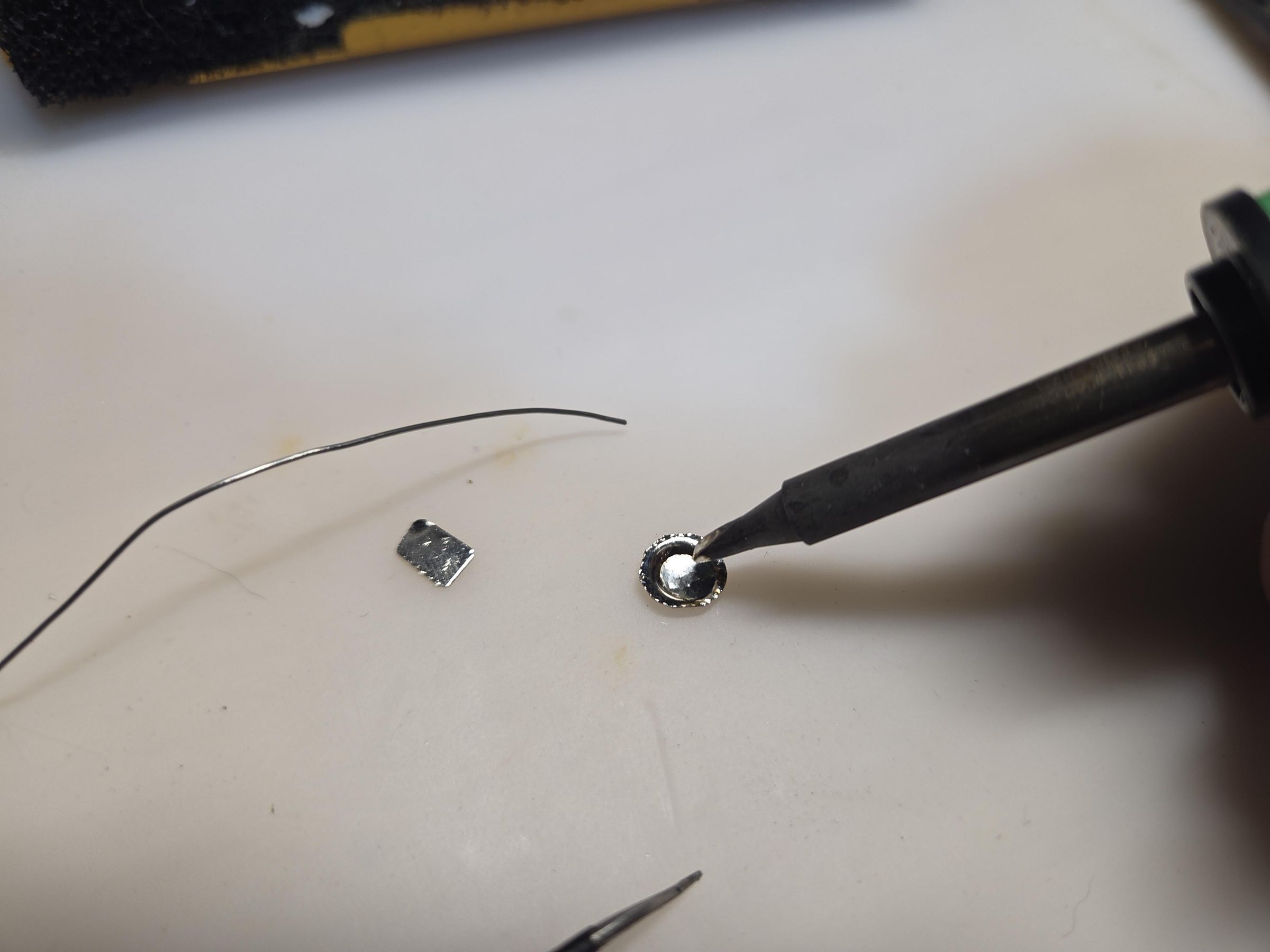
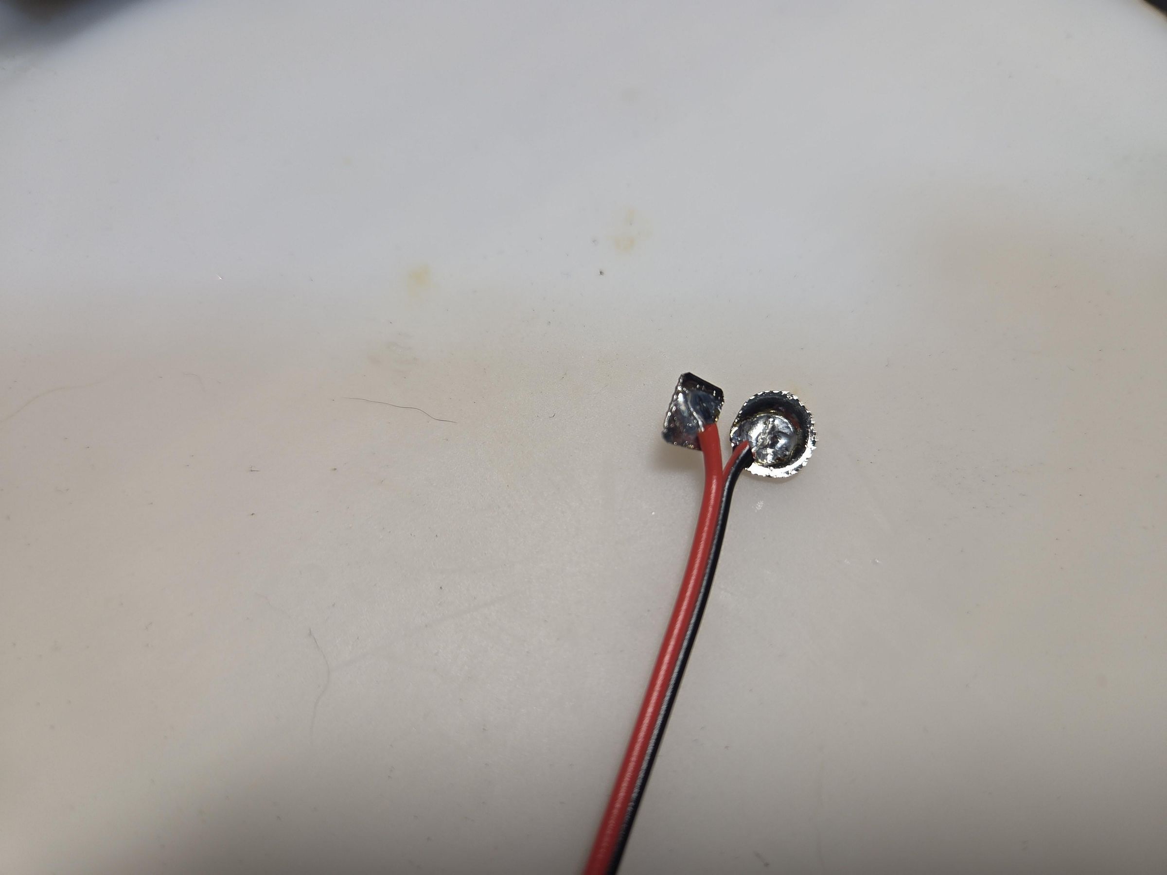
Since the rounded part of button batteries are negative (black), solder the negative wire to this on the inside of the bump.
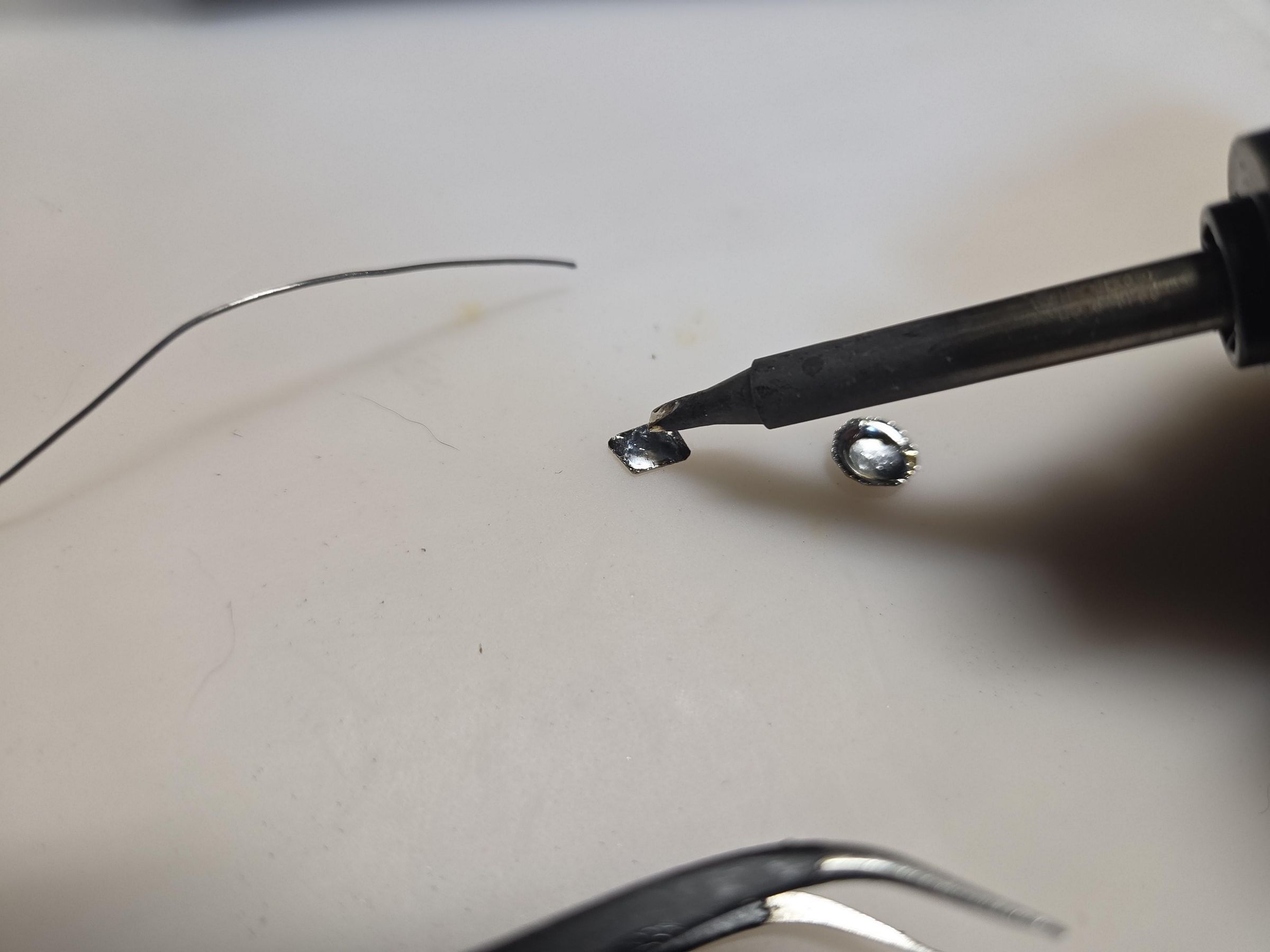
Solder the positive (red) wire to the flat terminal.
Pretty much it. If you have connected pair wires, try not to split them to far.
Glue Terminals in Place
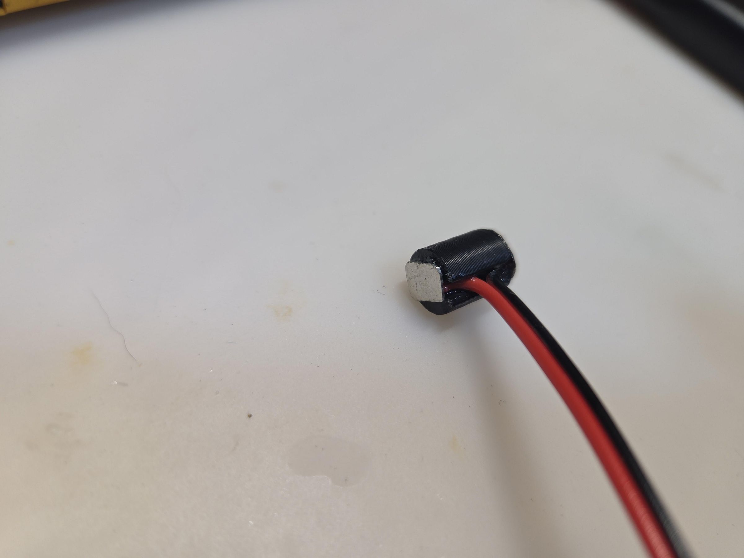
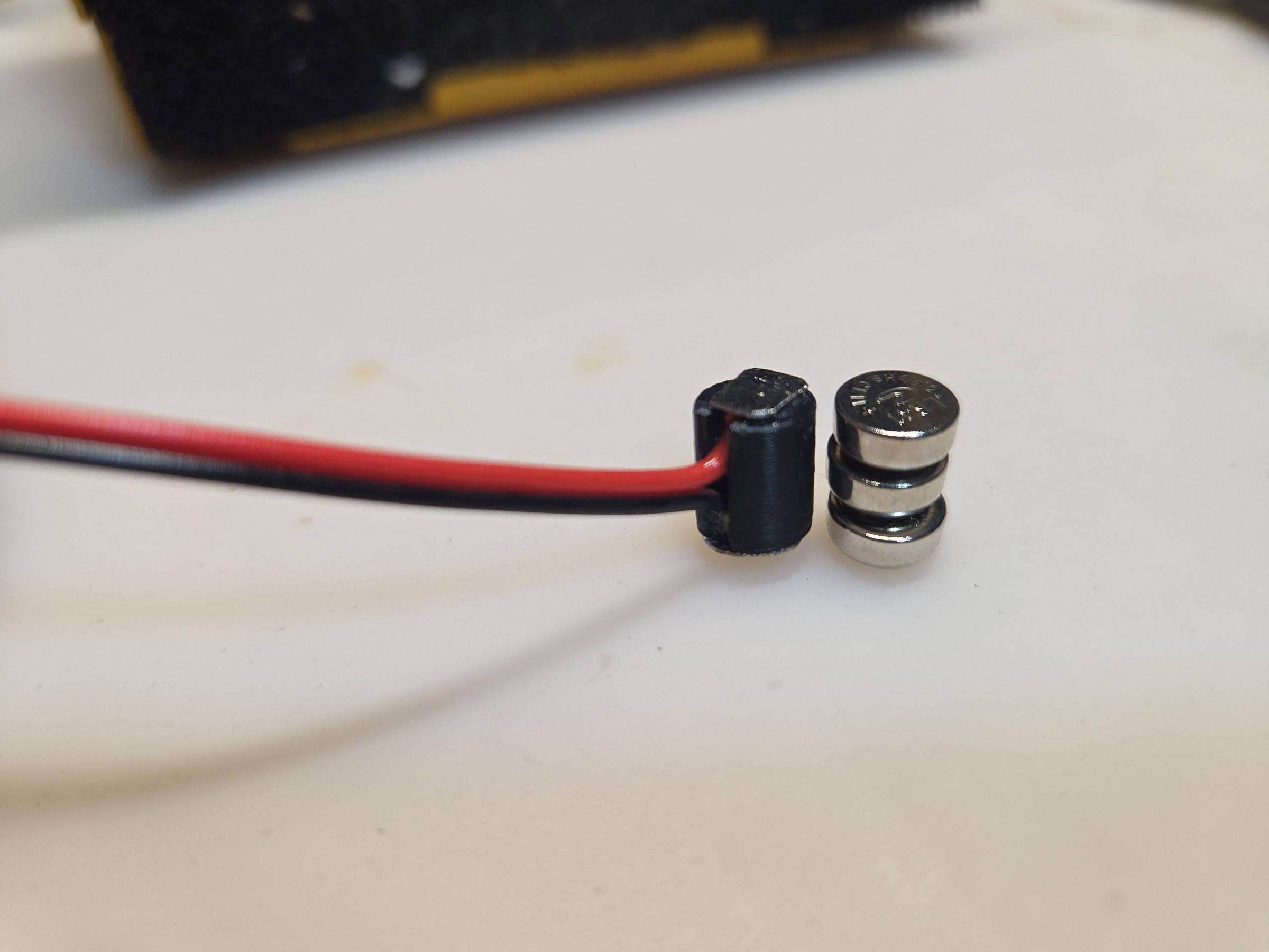
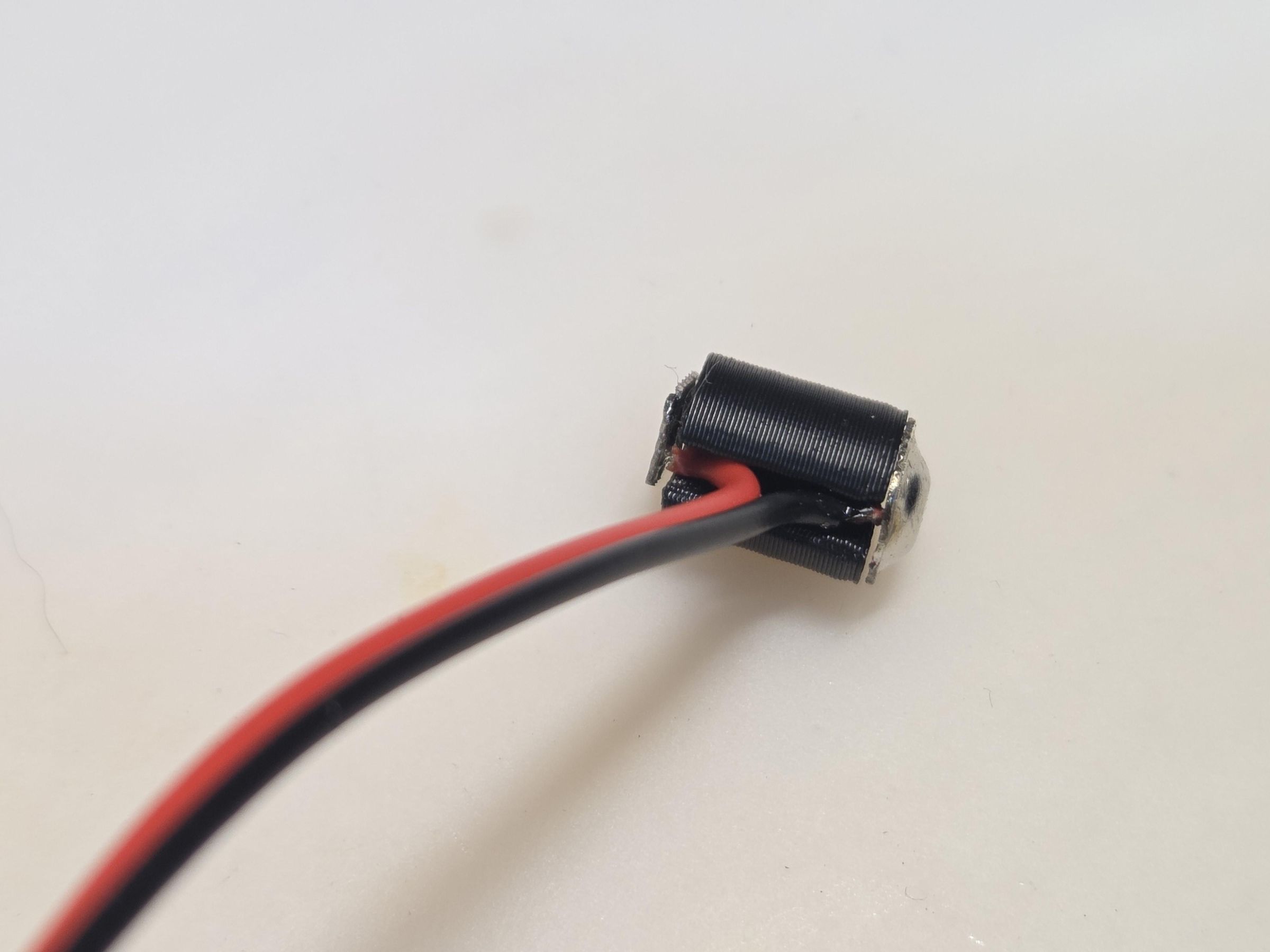
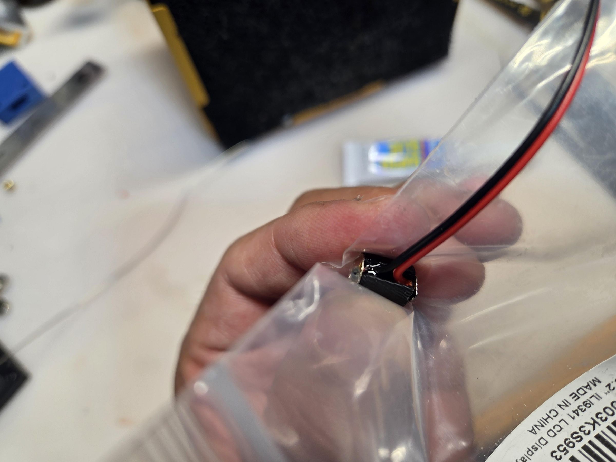
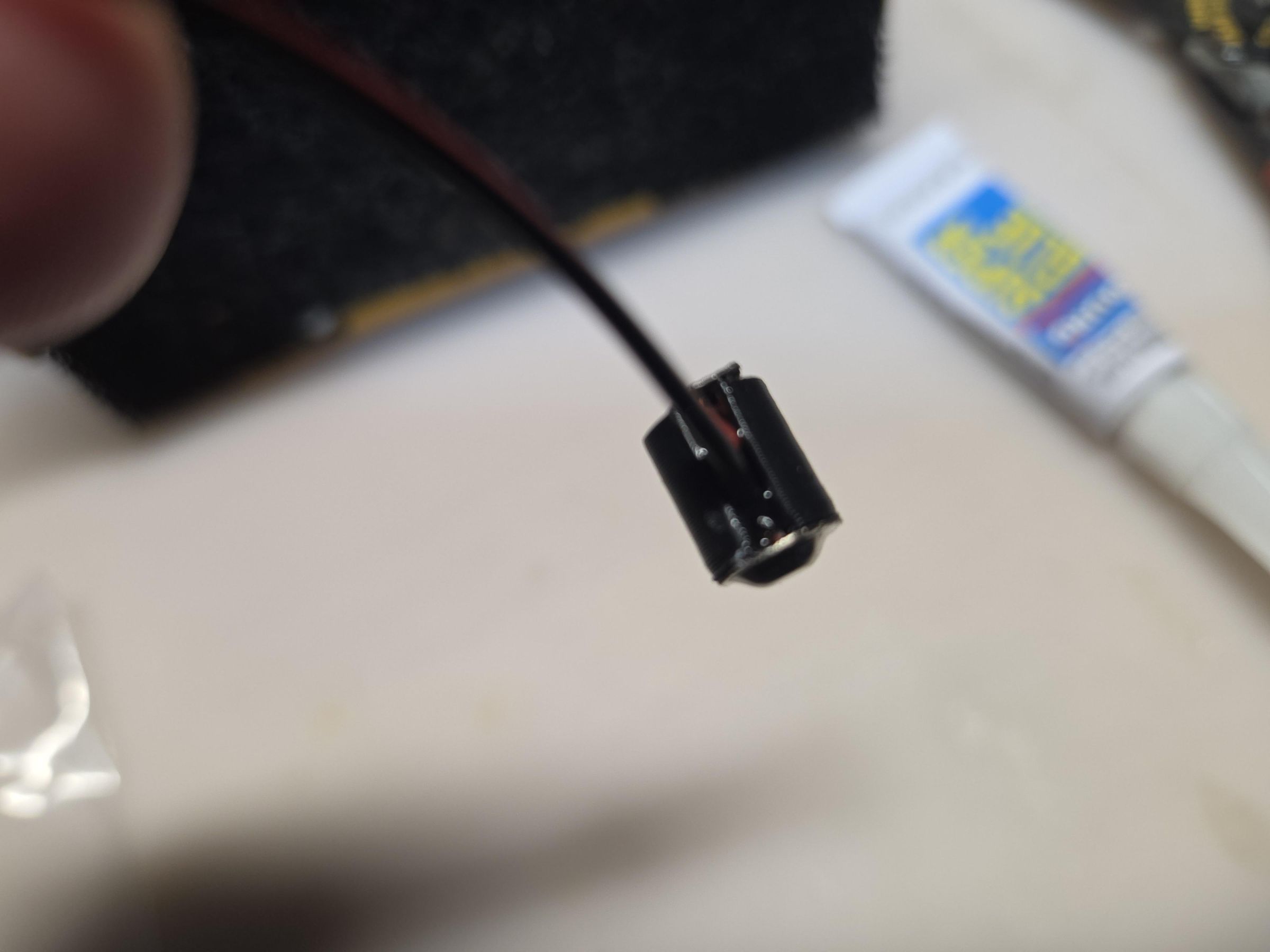
Place the terminals on opposite ends of the battery dummy print.
Route the wires in the middle channel of the battery dummy.
Center a terminals as best you can on the end of one side and apply a small amount of super glue to hold it in place. Use super glue accelerator if you have it.
Do the same for the other end.
Use some glue in the center channel to fix the wires in place. You don't need a lot and no need to fill the channel up with some filler like epoxy, unless you really want to for aesthetics.
If the terminals over hang the dummy, just file that piece off.
Diode Voltage Drop
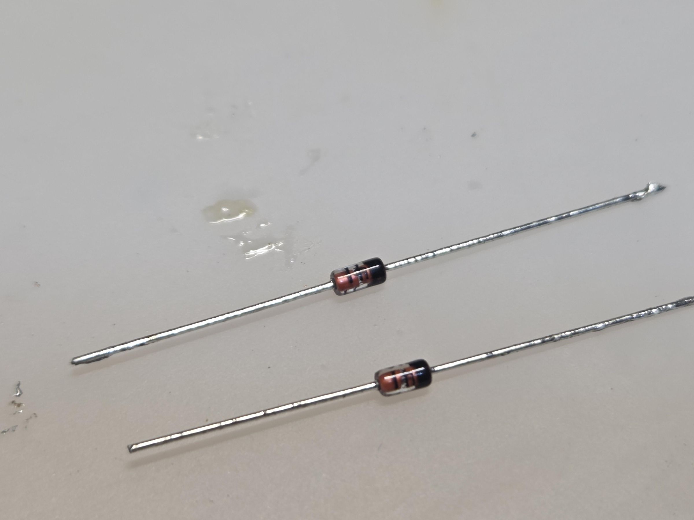
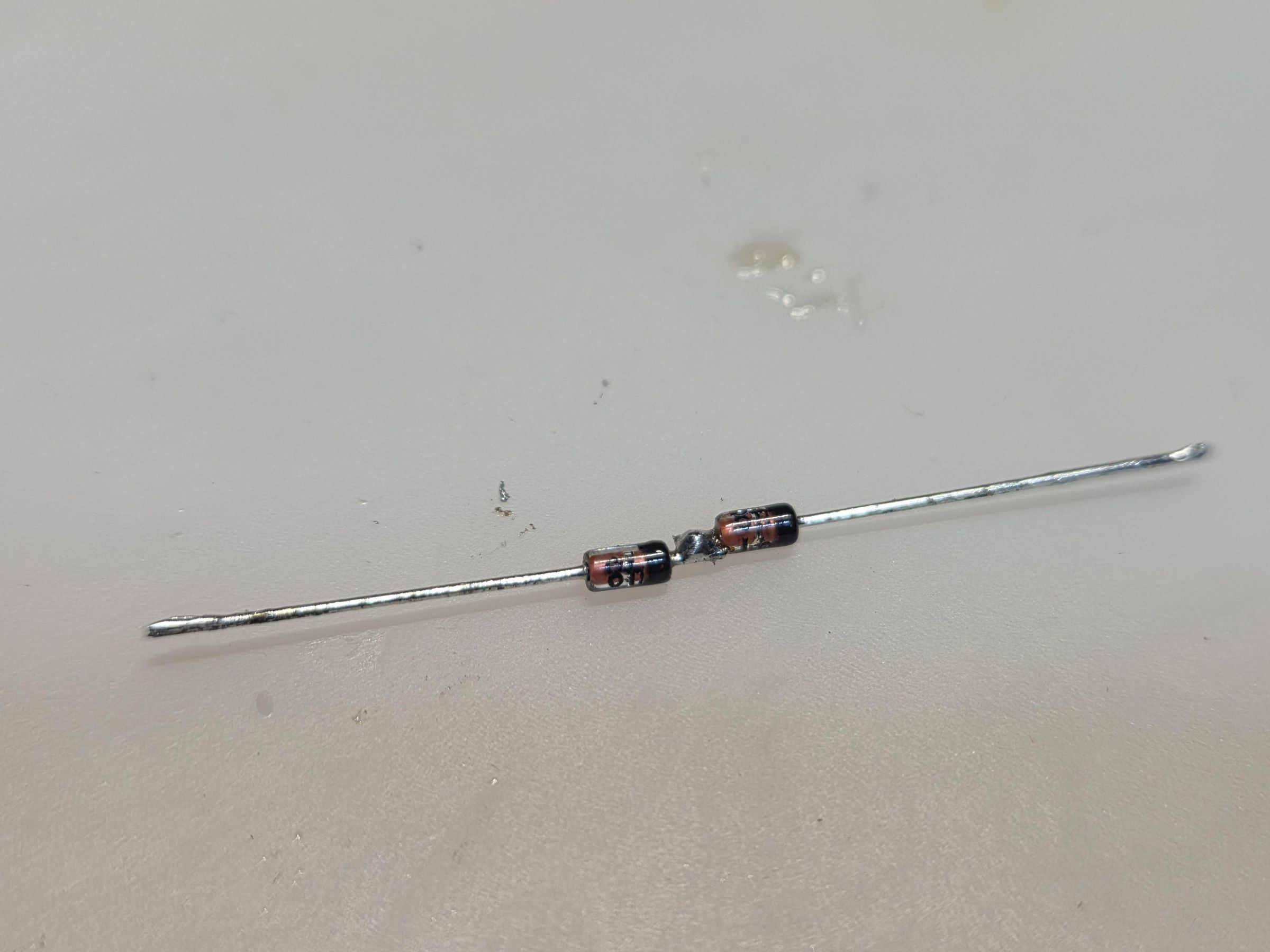
Standard USB voltage is 5V. The LR41 button cell battery voltage range from 1.5V to 1.55V. So using three stacked together can be from 4.5V to 4.65V. A quick and simple way to get the USB voltage down to that range or below is to just put a bunch of diodes in series with each other. A diode voltage drop varies by how much current. Datasheets say 0.4-0.5V on low current and 0.6-0.7V for normal current. Chances are, since using button cell batteries, the device is low current. So just solder 2 and measure the voltage drop when you apply 5V. I used 2 diodes in series and voltage dropped from 5.0V to 4.6V with no load. So, with some load it should be below that voltage.
Note:
Final voltage in the device I used the dummy battery with two diodes in series is 4.0V. Probably could have just used one diode.
Attach Diodes to USB-C Module
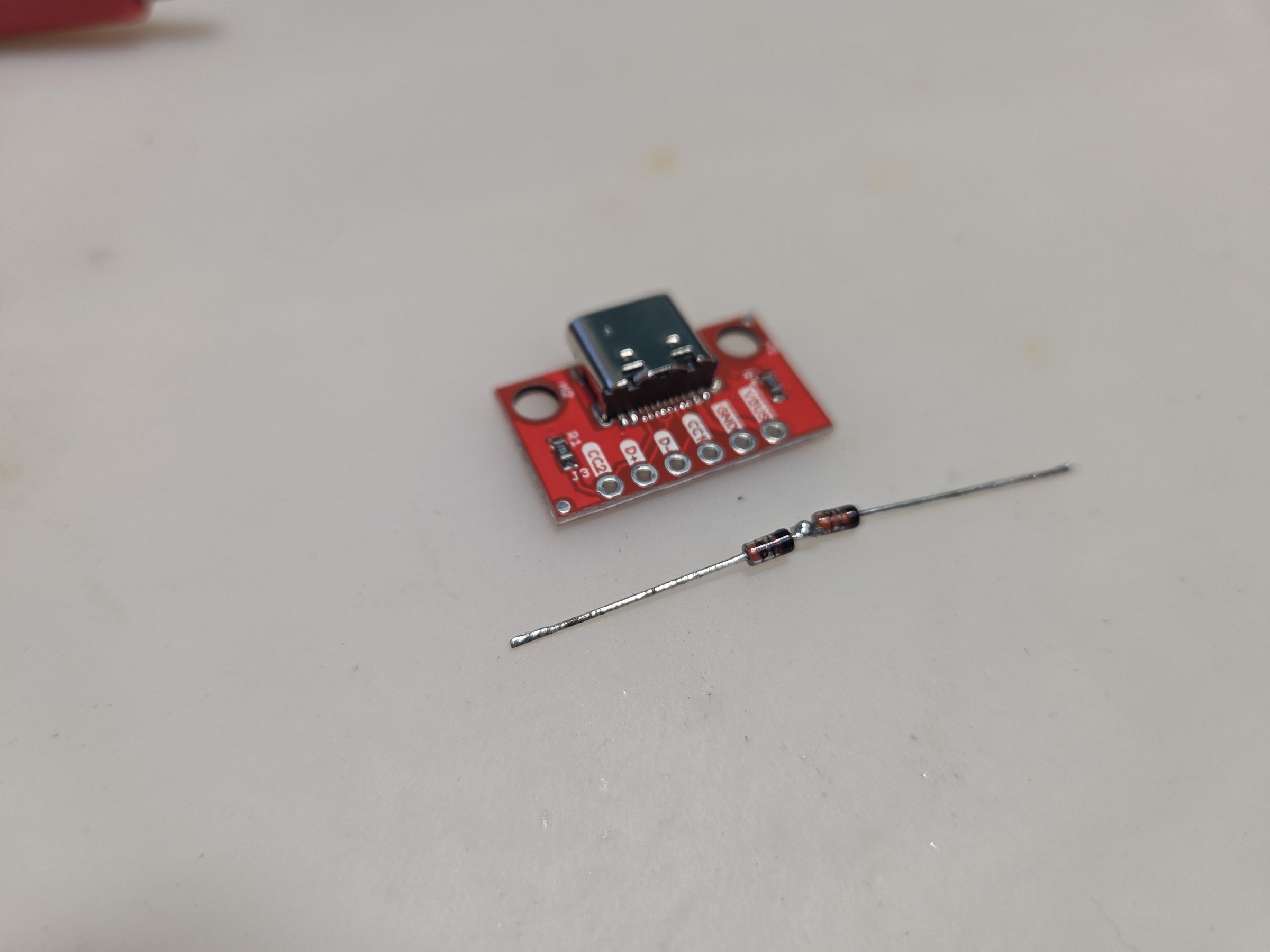
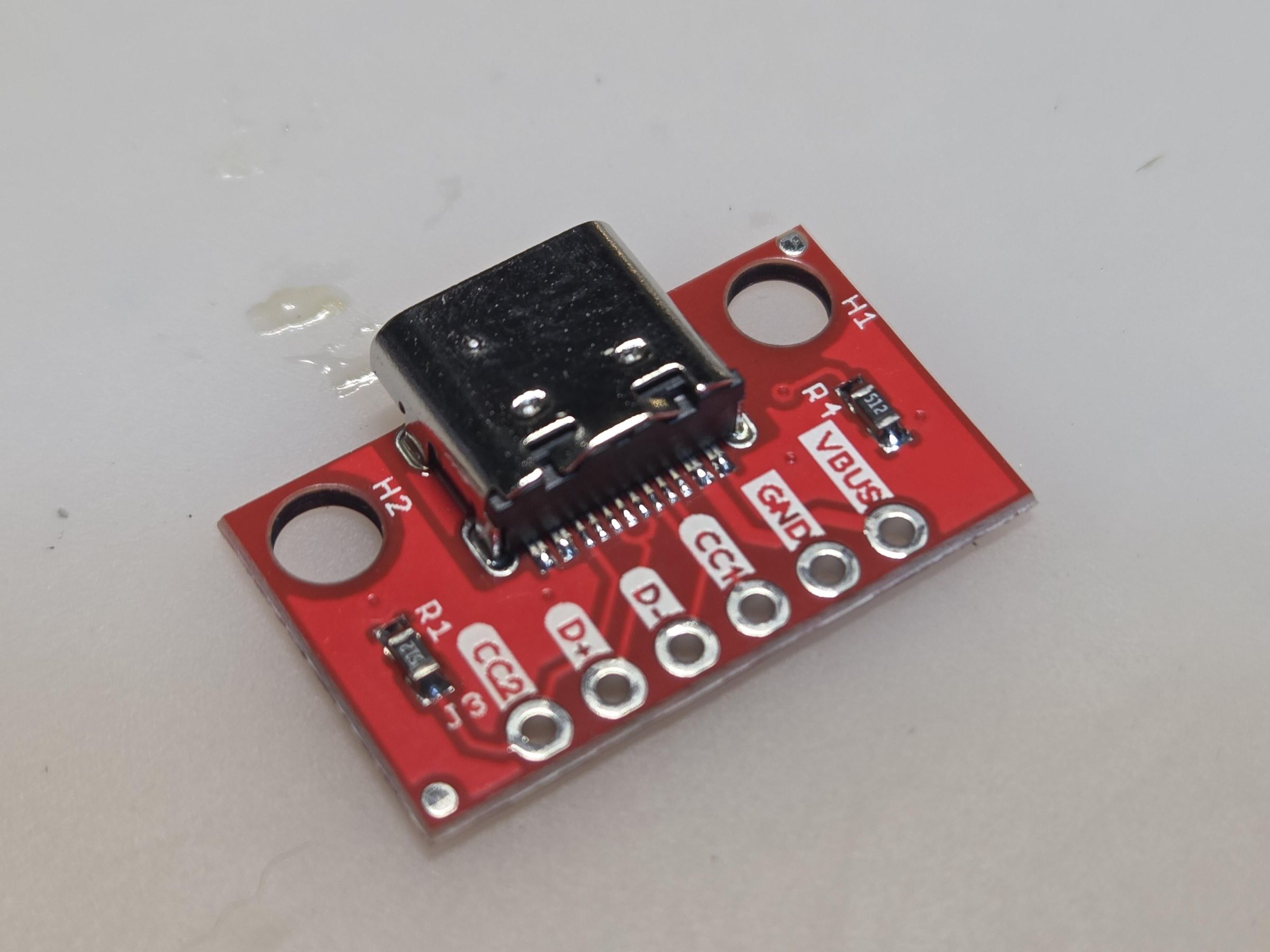
There are different types of USB-C breakout modules. If you want to use USB-C to USB-C cables you will need to use modules that have the CC lines pulled to ground. If the USB-C module does not have that, you need to use USB-A to USB-C cables. The reason being, the USB-C module cannot tell the charger what voltage to use.
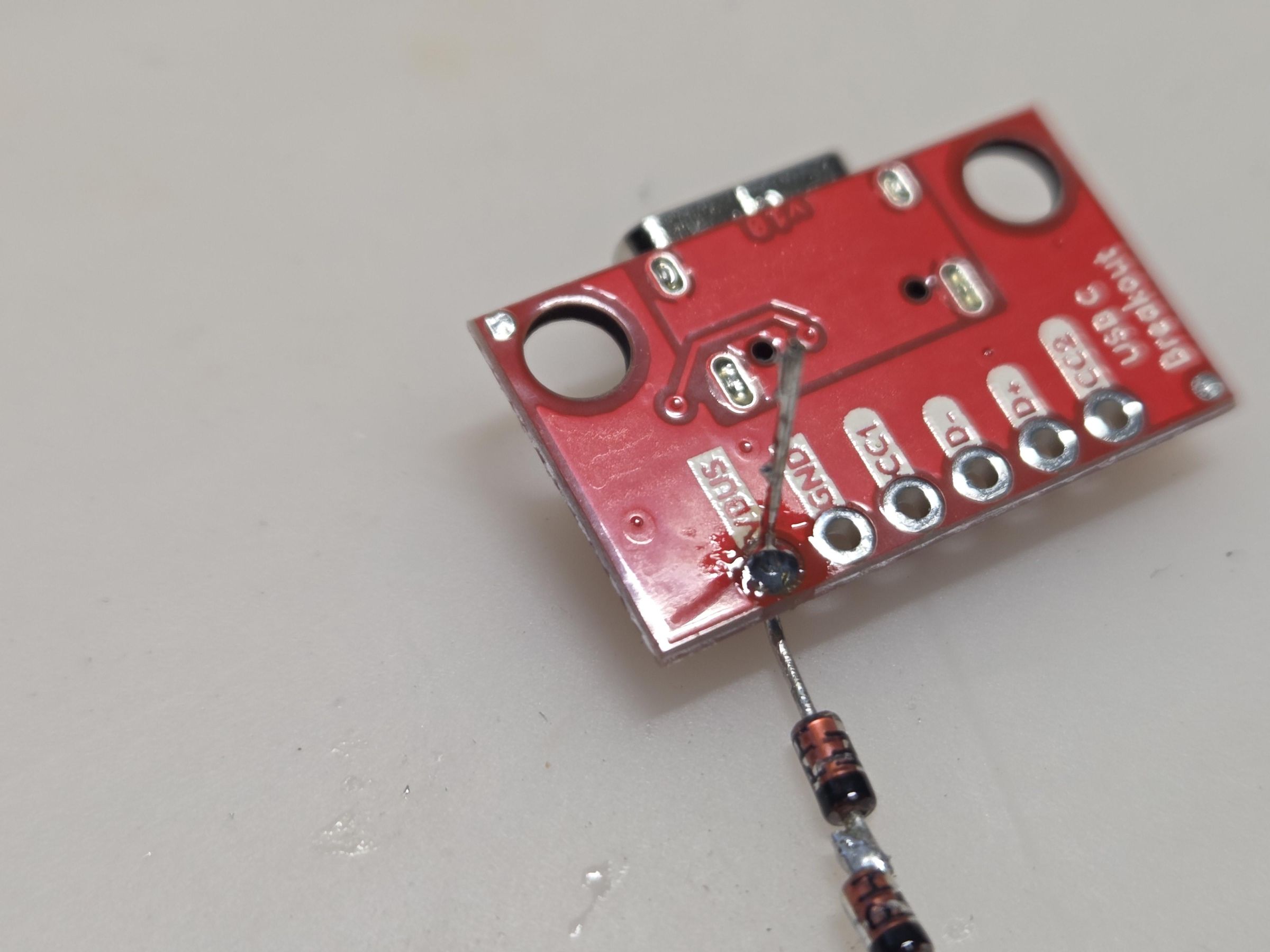
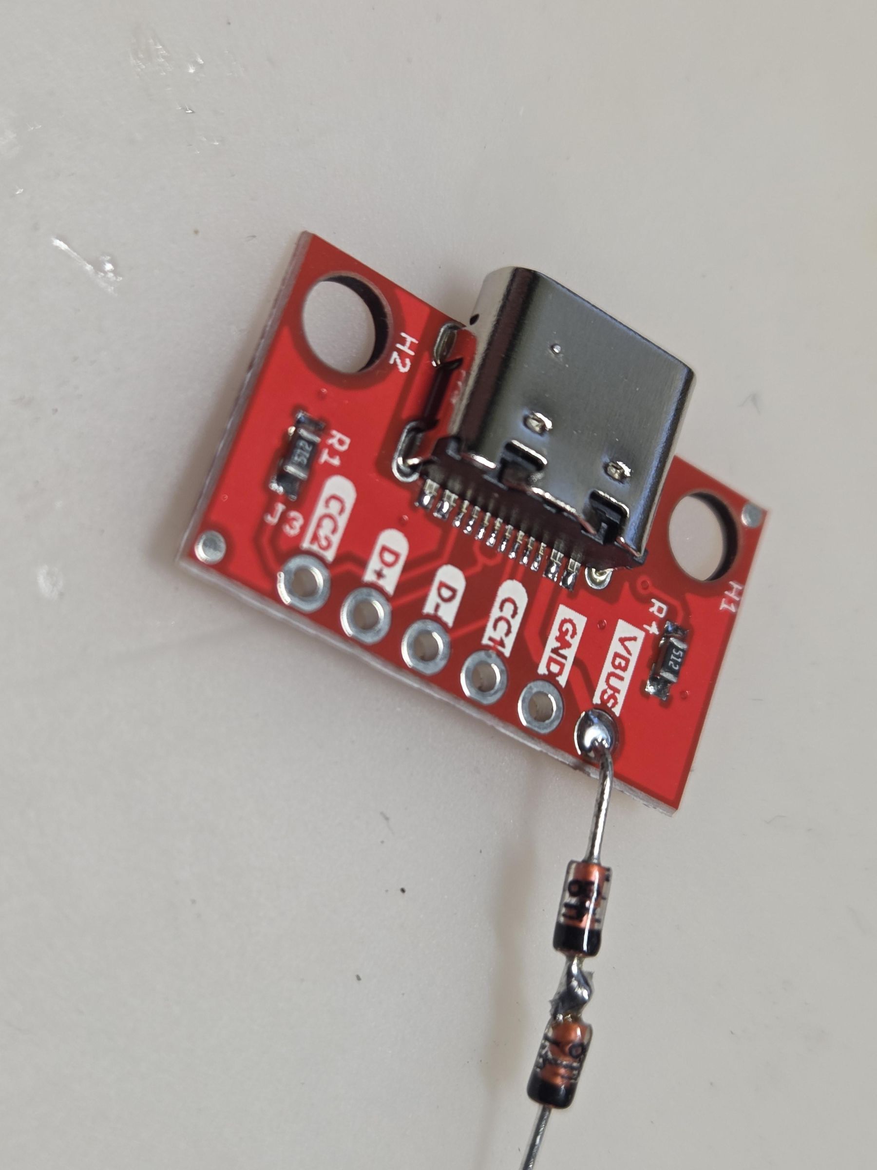
Solder the series diodes from the previous step to the positive voltage pad (VBUS on the pictured module). Leave about 3mm of leg room from the module to the diodes so that you can bend the leads to fit in the case when you attach the wires. Make sure to solder the diodes in the correct orientation (black stripe away from the positive pad).
Attach Wires to Module
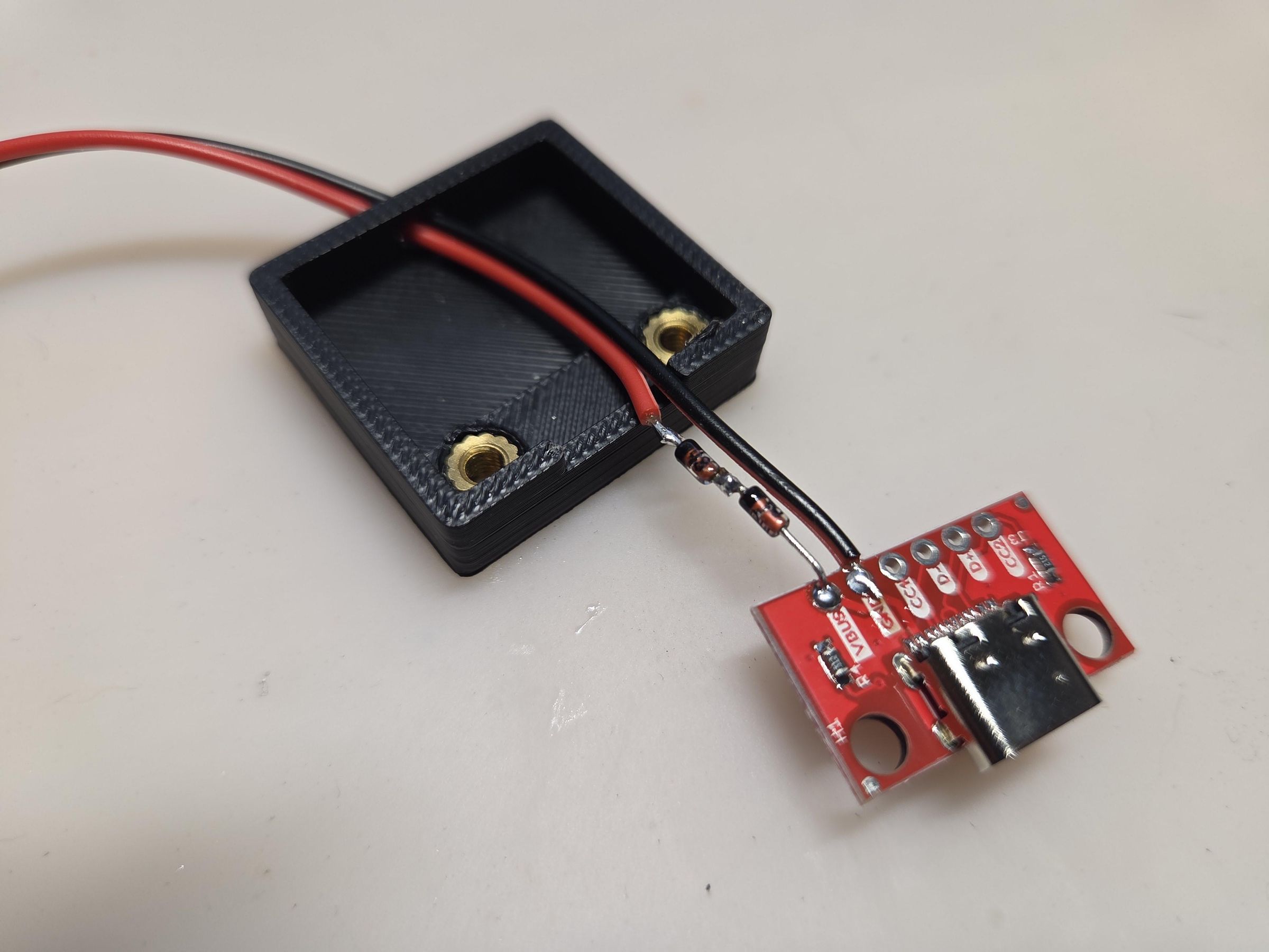
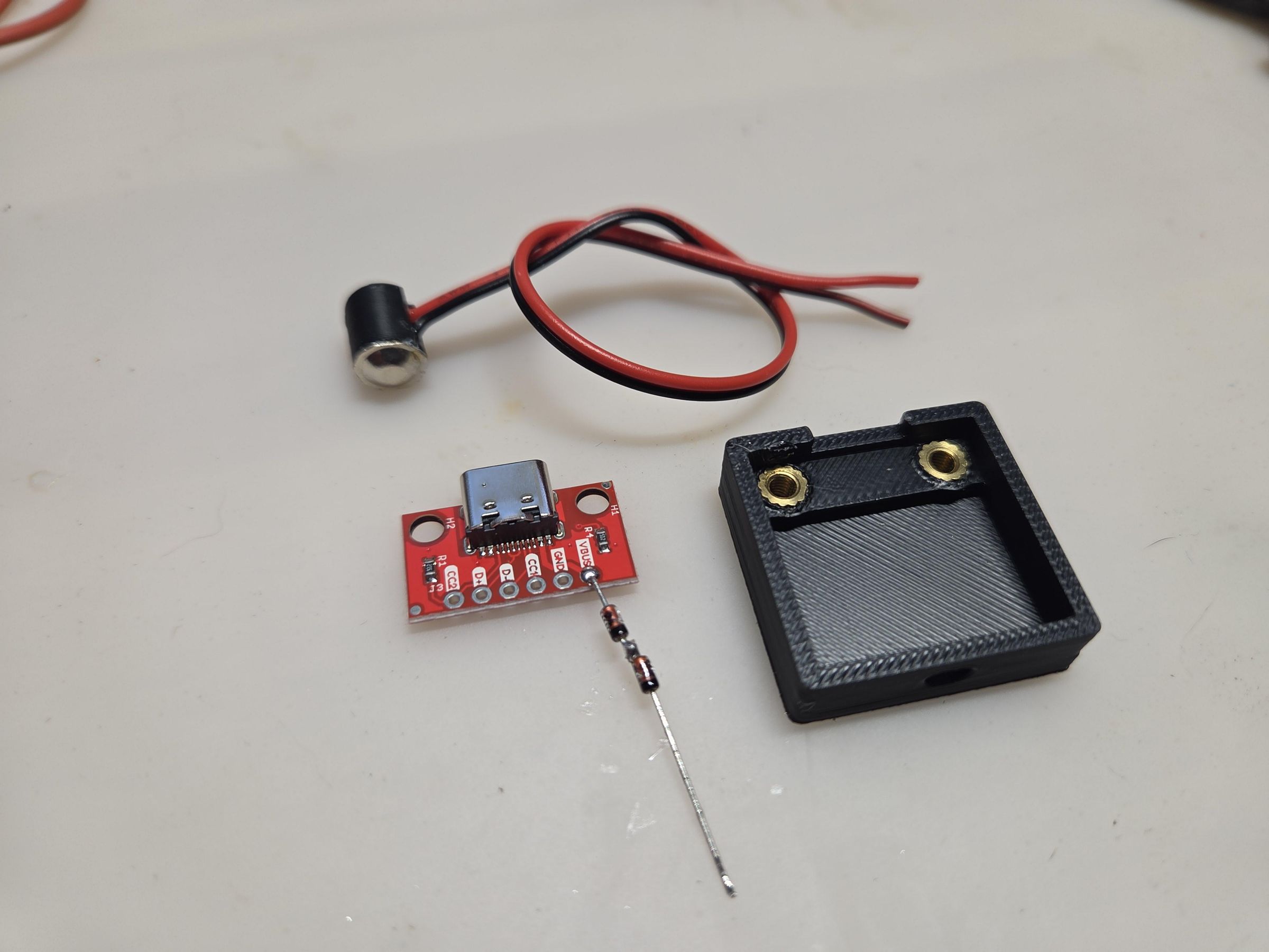
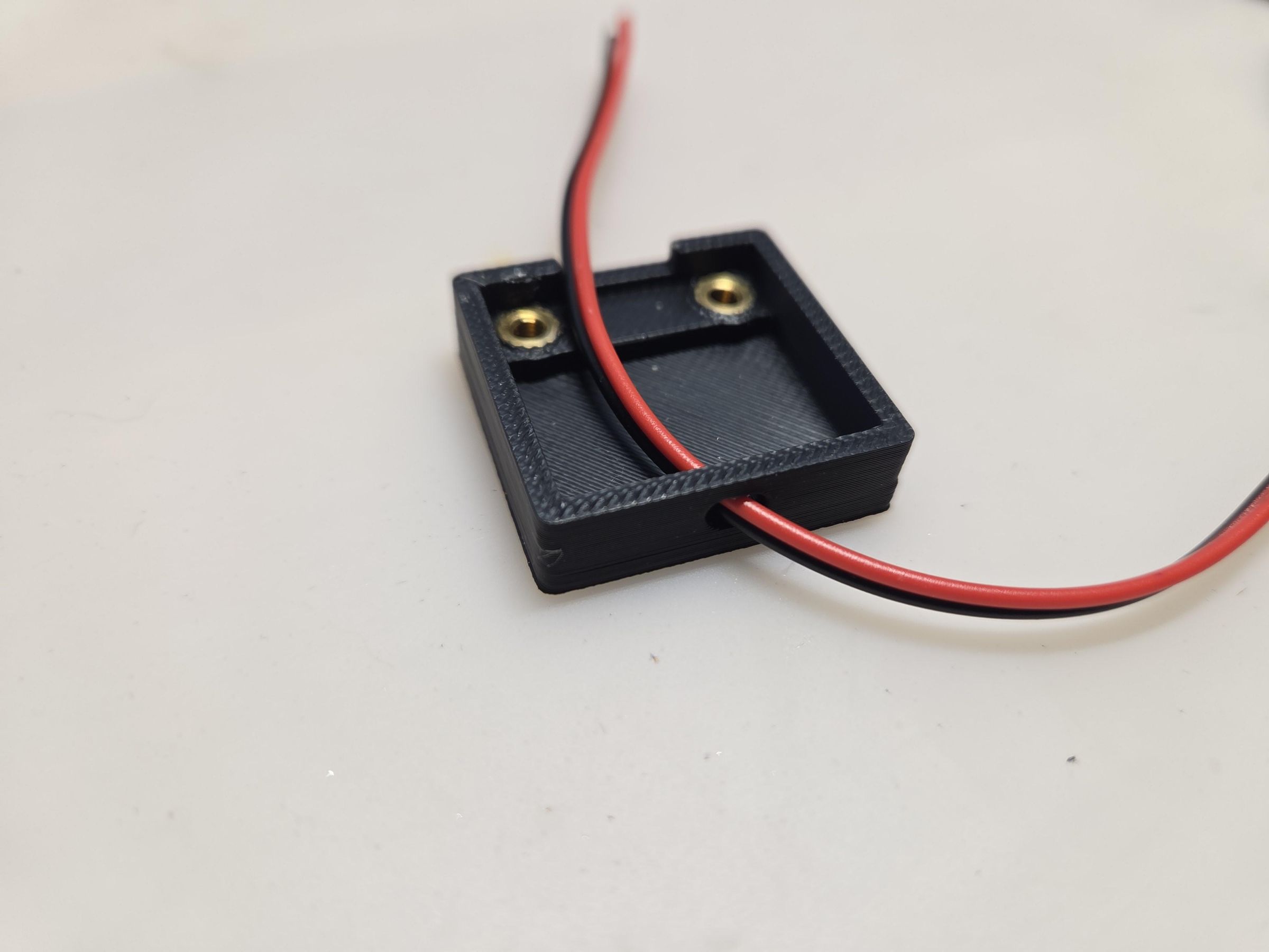
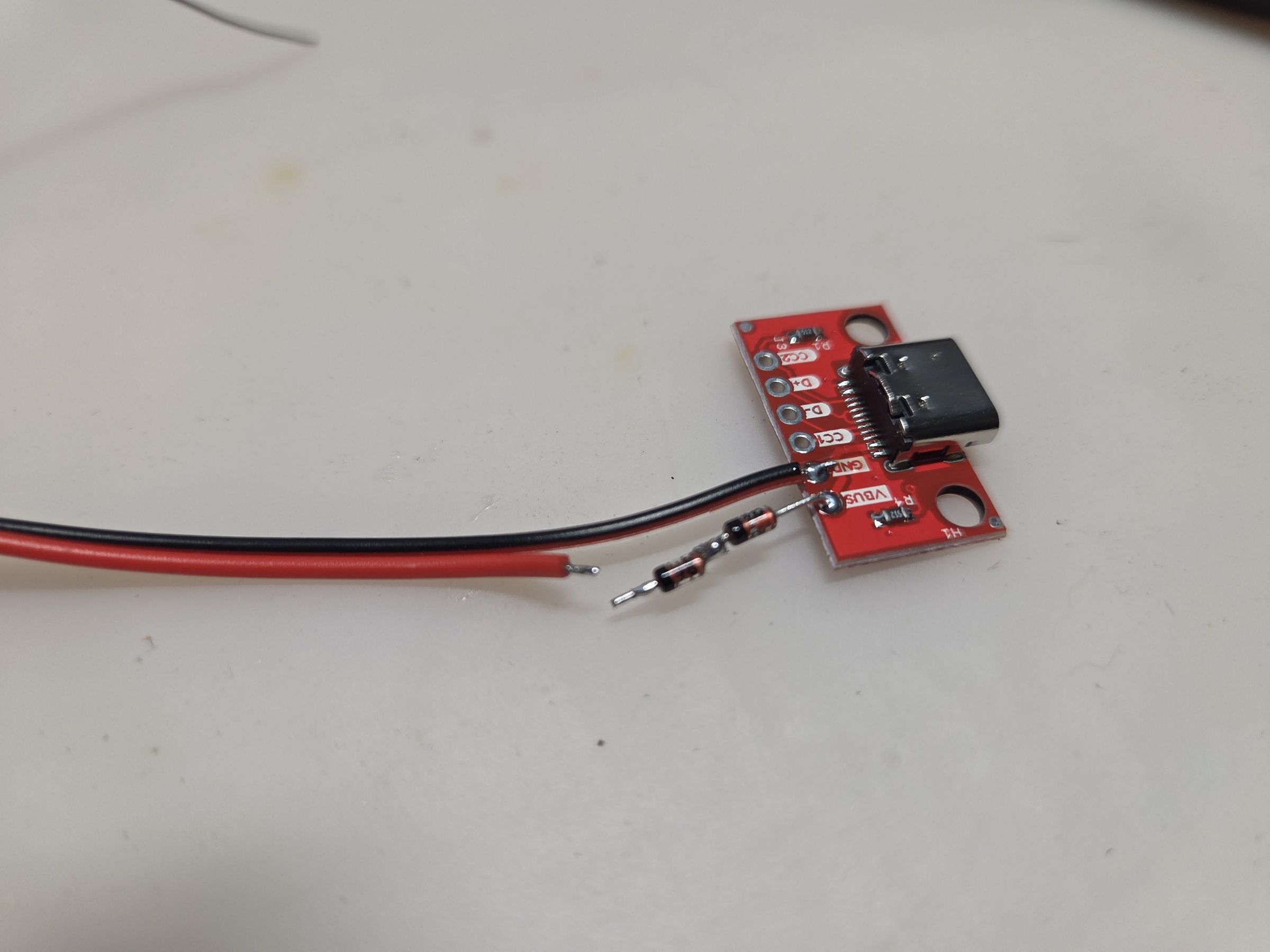
Run the wires from the dummy through the hole in the bottom of the case.
Solder the negative (black) wire to the negative pad of the USB-C module.
Solder the positive (red) wire to the end of the series diodes.
Note:
I ended up going back to this step to put the wires through the device's battery cover, so plan ahead unlike me. Since you have wires come out now of the device, if you want to use the original cover alter the cover to let your wires through.
Quick Voltage Test
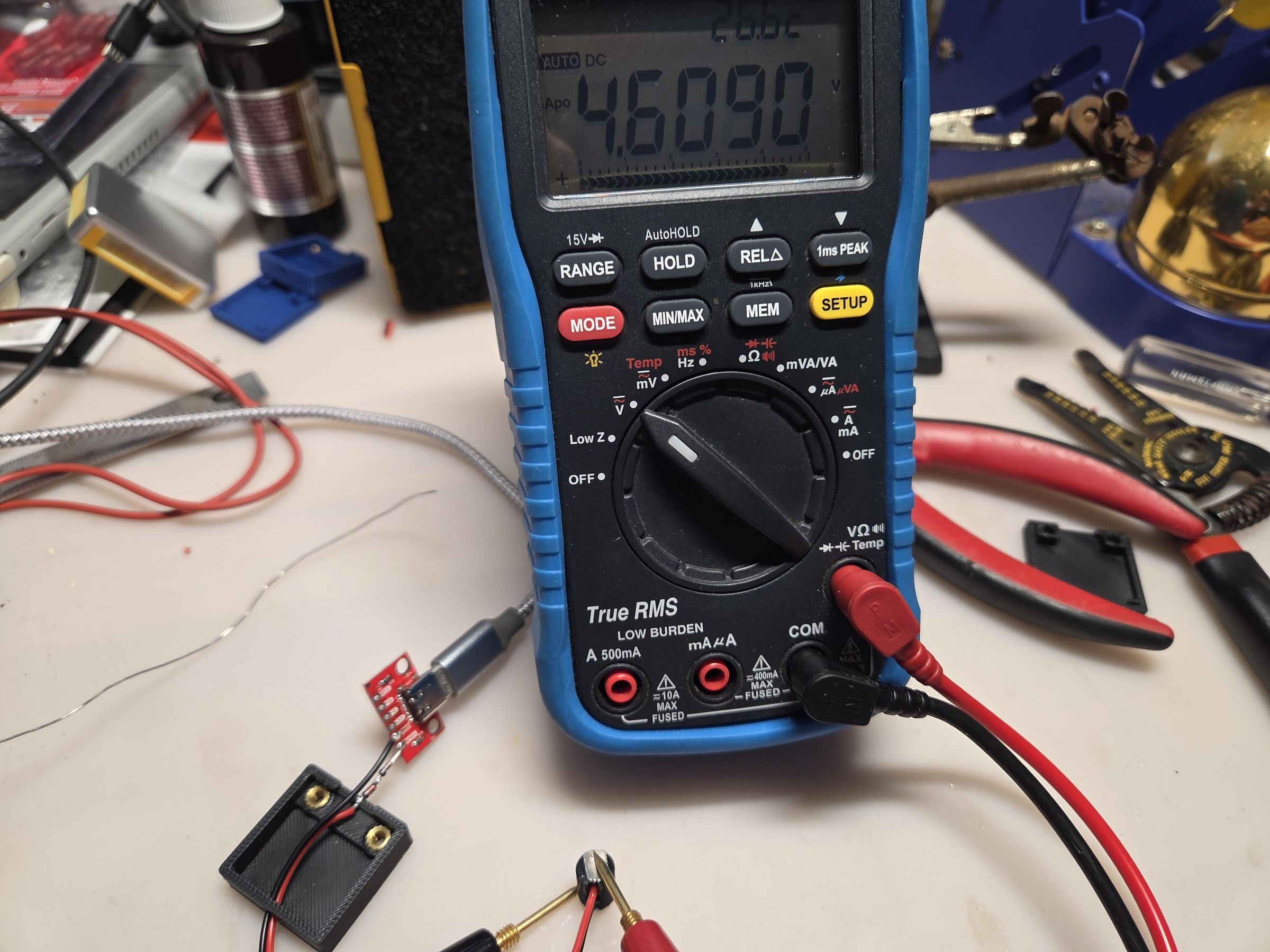
Check that you are getting near the 4.5V when plugged into a USB-C power source.
Ensure the bump part of the dummy is negative.
If all good, move on. If not, double check your wiring.
Boxing It Up
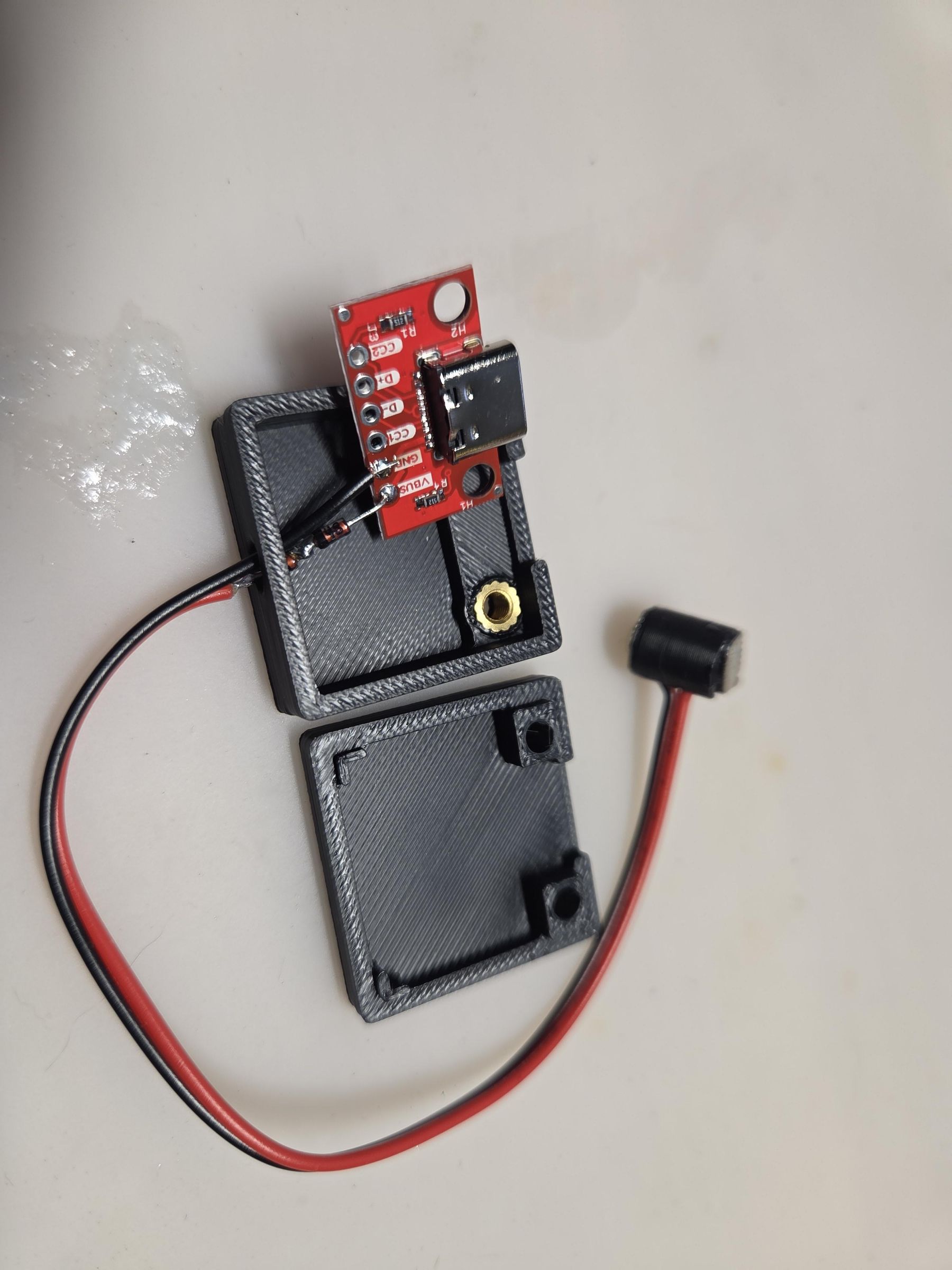
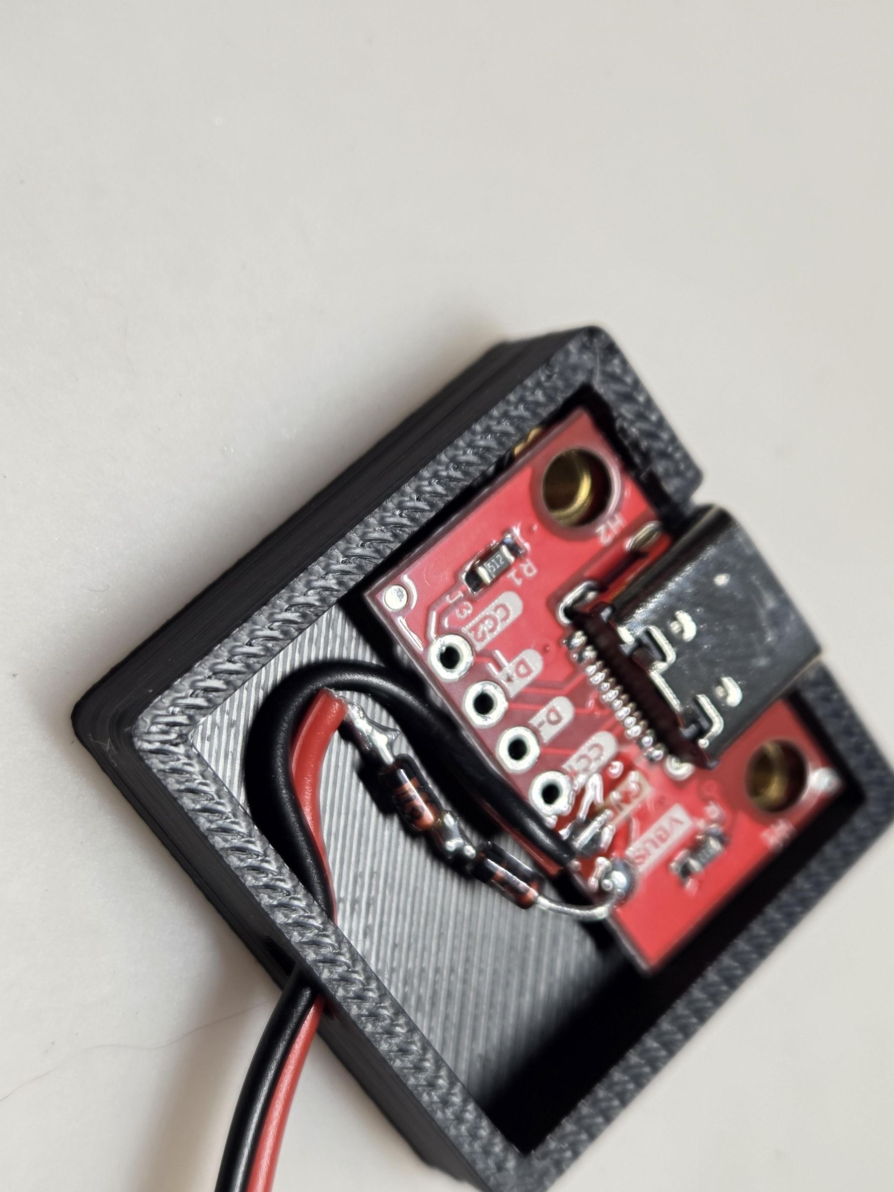
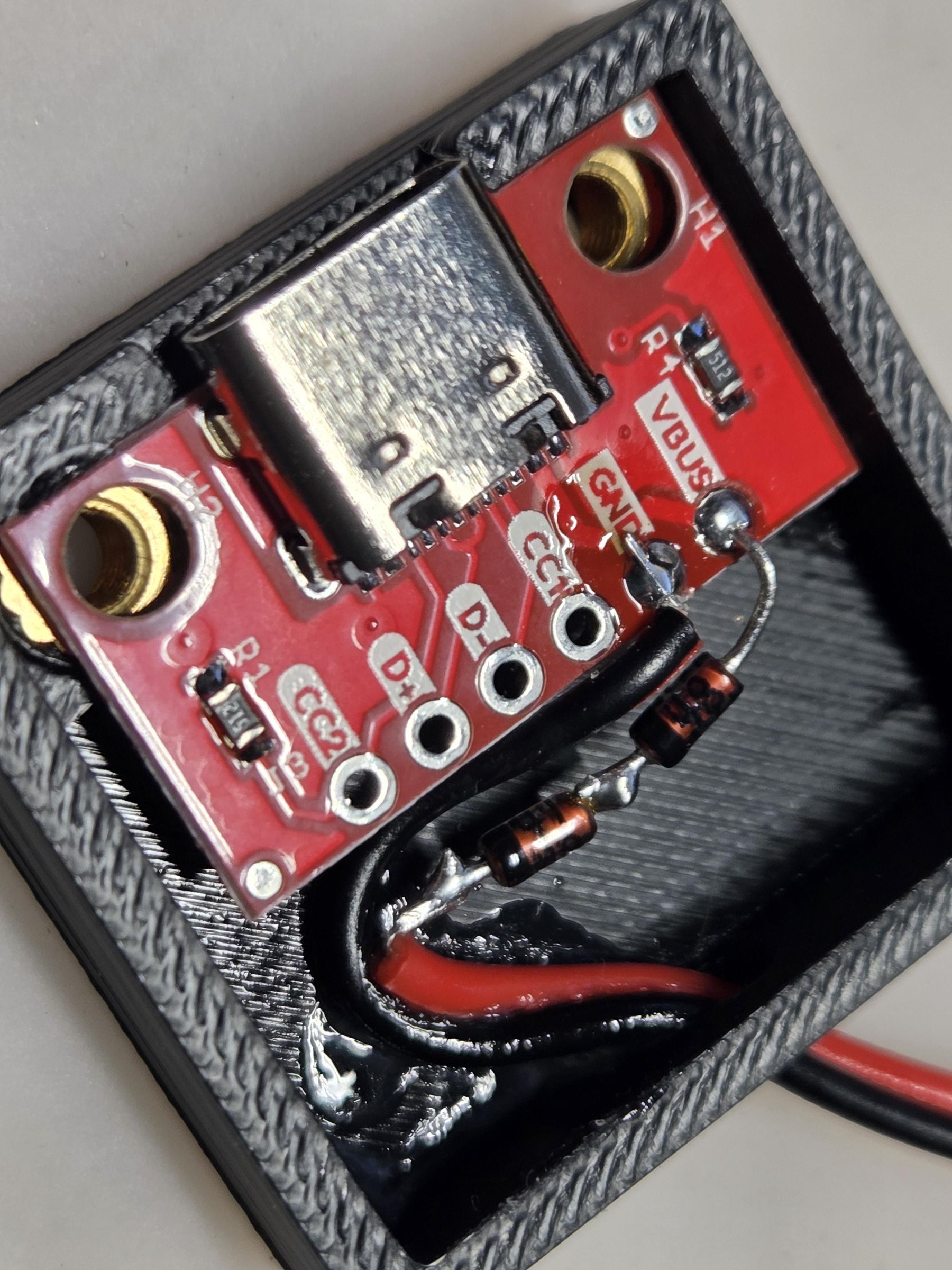
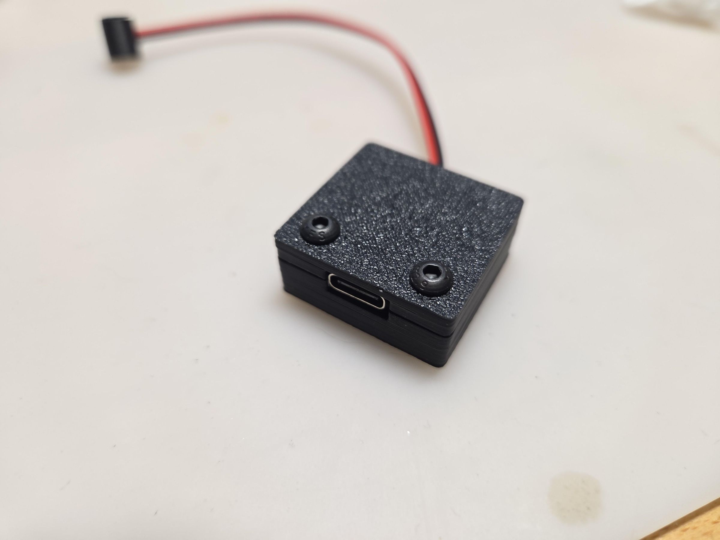
Line up the USB-C module in the case and route the wire/series diode to make it all fit.
Optionally you can put a bit hot glue to lock the wires in place and some strain relief (I got lazy and just put a drop of super glue and accelerator).
Put the case cover on and screw it closed.
Use It
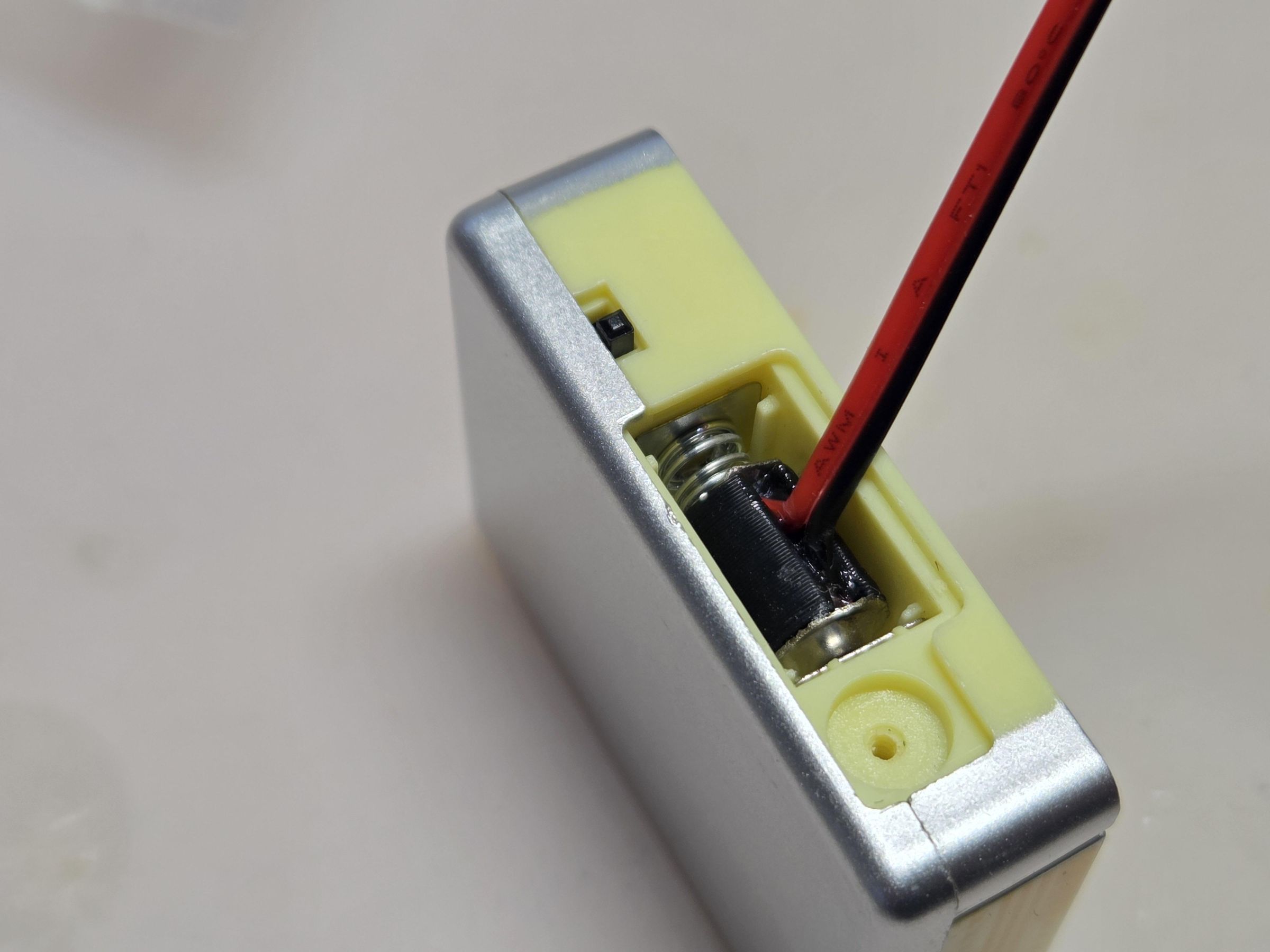
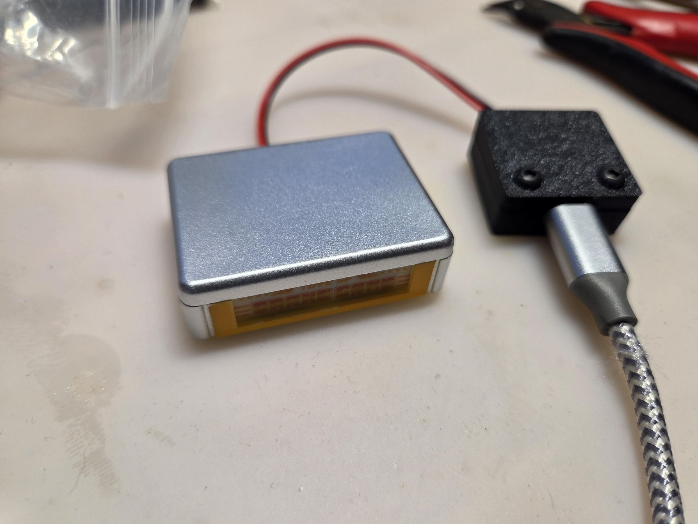
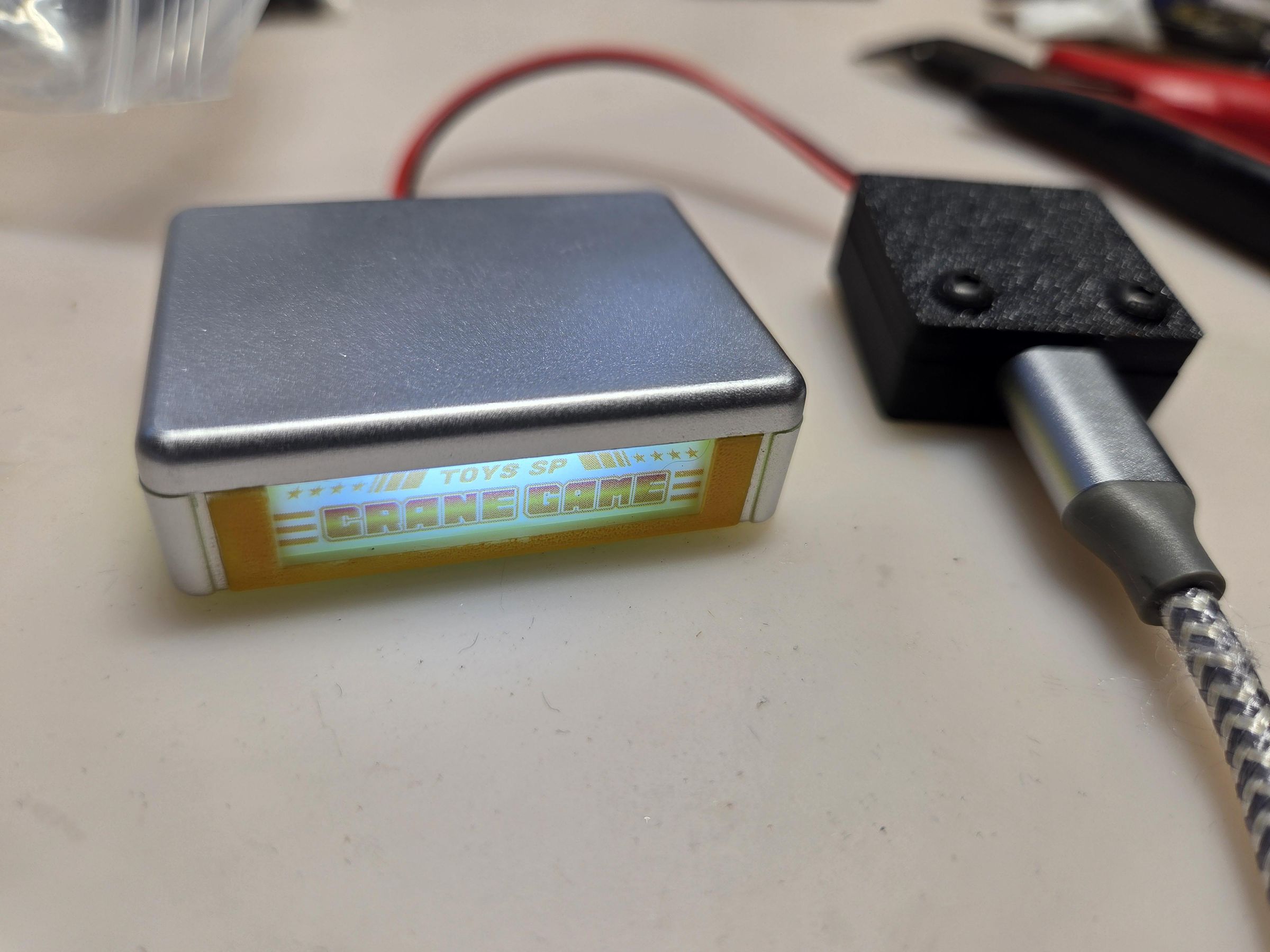
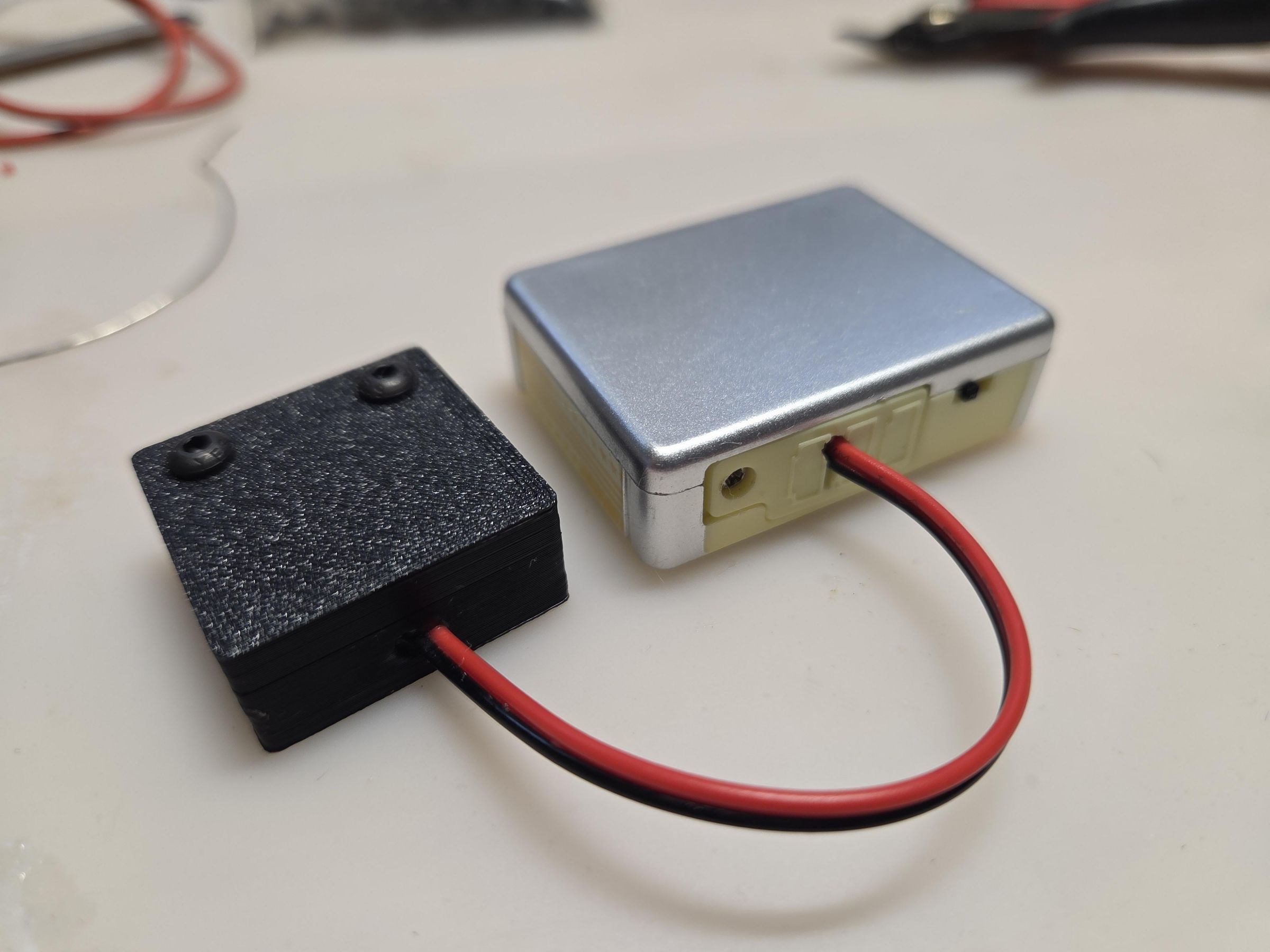
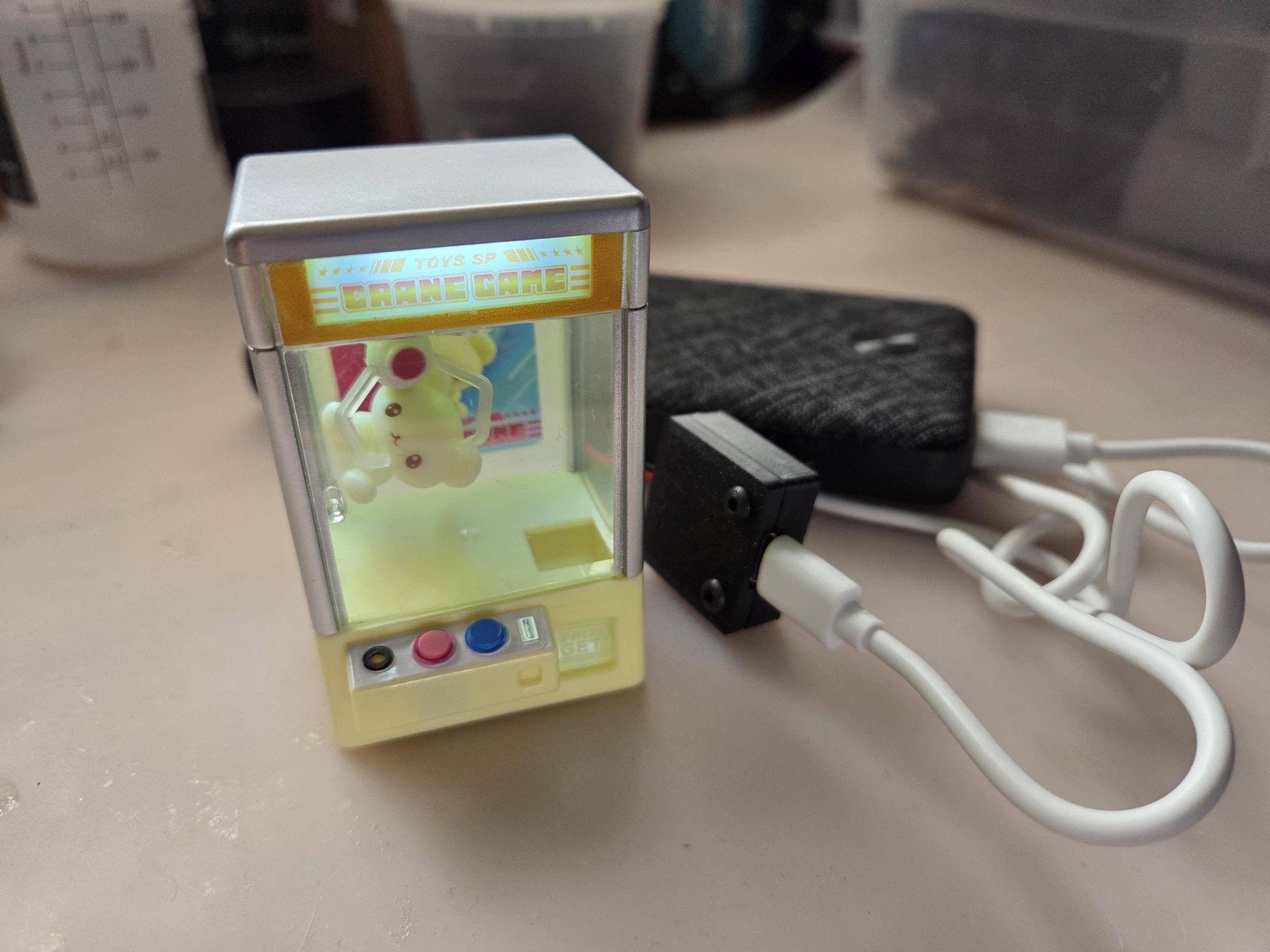
Use like how you would with batteries. A bonus is that you don't have to fumble with each individual battery cell, where you try to put in the last cell and they all pop out.
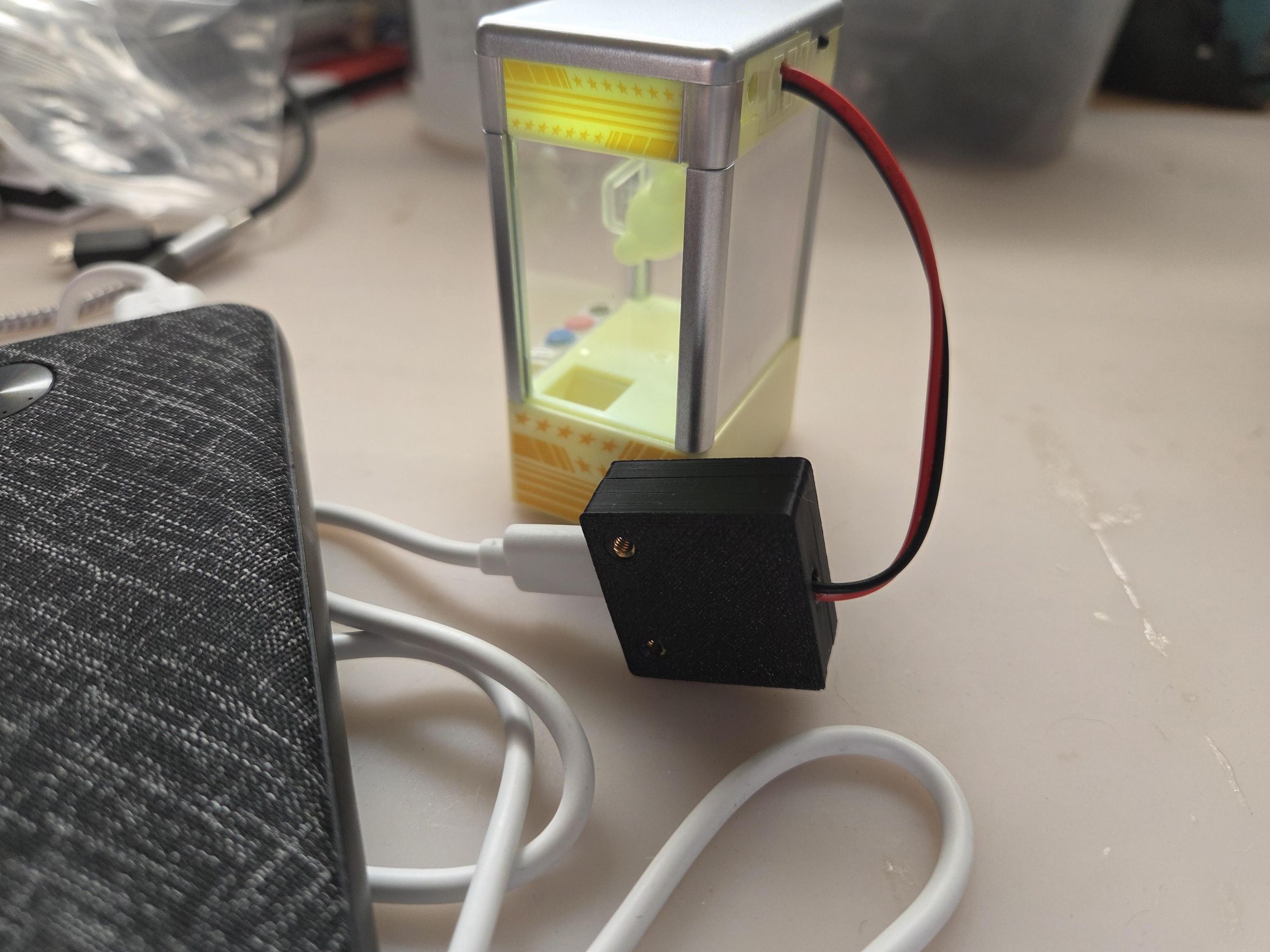
One drawback is now that you have a wire sticking out. So plan ahead on how you want to secure the battery dummy in place since you will have to cut out a notch in the battery cover of the device you are using.
I ended up re-soldering the wires back in to the case since I wanted to use the original device battery cover. Had to put the wires though the cover first before connecting to the module.