USB Sensor Bar
This is how to make a sensor bar that can be used with a Wiimote and has a usb interface. It works fine with the Wii as well as the PC while using a program that allows to use the wiimote as a joystick (such as Glovepie) and is compatable with IR tracking.
Assembly is simple and can be done by anyone. For this instructable I used Legos to house the wires and LEDs, but anything that will fit them will work.
Assembly is simple and can be done by anyone. For this instructable I used Legos to house the wires and LEDs, but anything that will fit them will work.
Supplies
For this project you will need:
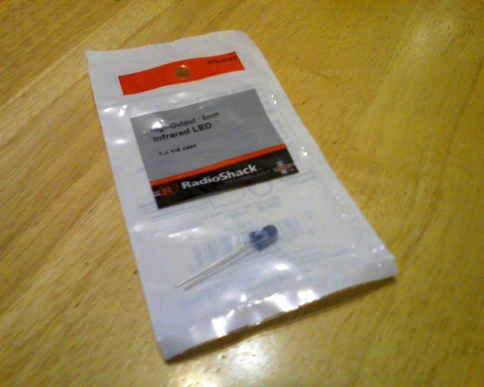
4 infrared LEDs
1 USB cable
Electrical tape (optional)
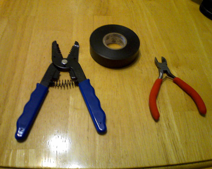
wire cutter
wire stripper (optional)
something to house the LEDs and connections
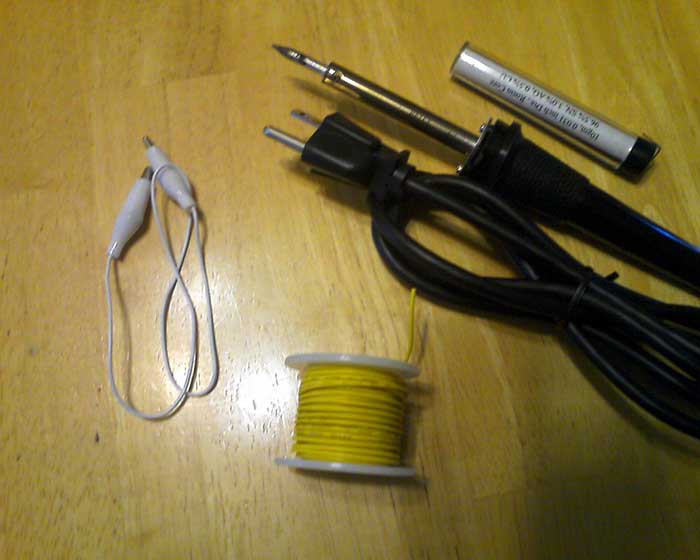
and you will also need wire and a soldering iron OR 5 alligator clips.
If you use alligator clips it makes making the connections easier, but it will be harder to place it in a compact case.
4 infrared LEDs
1 USB cable
Electrical tape (optional)
wire cutter
wire stripper (optional)
something to house the LEDs and connections
and you will also need wire and a soldering iron OR 5 alligator clips.
If you use alligator clips it makes making the connections easier, but it will be harder to place it in a compact case.
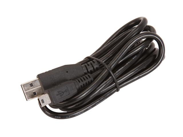
Open Up the USB Cable
Use the wire cutters to cut off the end of the USB cable that does not go into the usb port.
Cut down the end of the plastic covering the wires about an inch down and cut off the rest of the plastic up to that point.
You should see 4 different colored wires. red, black, green, and white. Cut or pull back the green and white wires and tape them down. You don't need these wires since those are used to carry information.
Now strip the red and black wire about 1/3 of the way or so.
And insert the cord into your case.
Making the Connections
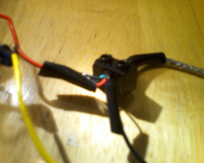
When connecting the LEDs together make sure that red wire is connected to the longer leg of the first LED and that the short leg is connected to the long leg of the next LED. The sort leg of the 4th LED will be connected to the black wire. Make sure you only use four LEDs (two for each side of the sensor bar) otherwise the LEDs won't be bright enough or may not light, unless you wire them differently, but we will keep it simple.
If you are using alligator clips all you have to do is clip them on. Simple.
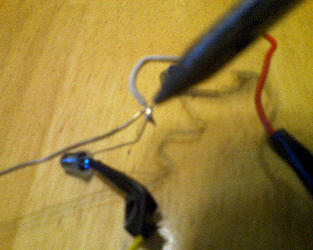
If you are new to soldering, make sure you have a damp sponge to keep the tip of the iron clean. Also be extremely careful not to touch any of the medal. I recommend soldering over cardboard that way if any solder touches it it won't stick easy. Just simply touch the wires together, put solder to it, and melt it with the soldering iron. The solder should stick to the wires. Also, try not to inhale the smoke.
If you are using alligator clips all you have to do is clip them on. Simple.
If you are new to soldering, make sure you have a damp sponge to keep the tip of the iron clean. Also be extremely careful not to touch any of the medal. I recommend soldering over cardboard that way if any solder touches it it won't stick easy. Just simply touch the wires together, put solder to it, and melt it with the soldering iron. The solder should stick to the wires. Also, try not to inhale the smoke.
Applying the Tape


I recommend that you tape one or both of the legs on each of the LEDs to prevent them from touching each other. You may also want to put tape over the connections you have soldered.
Testing the Connections
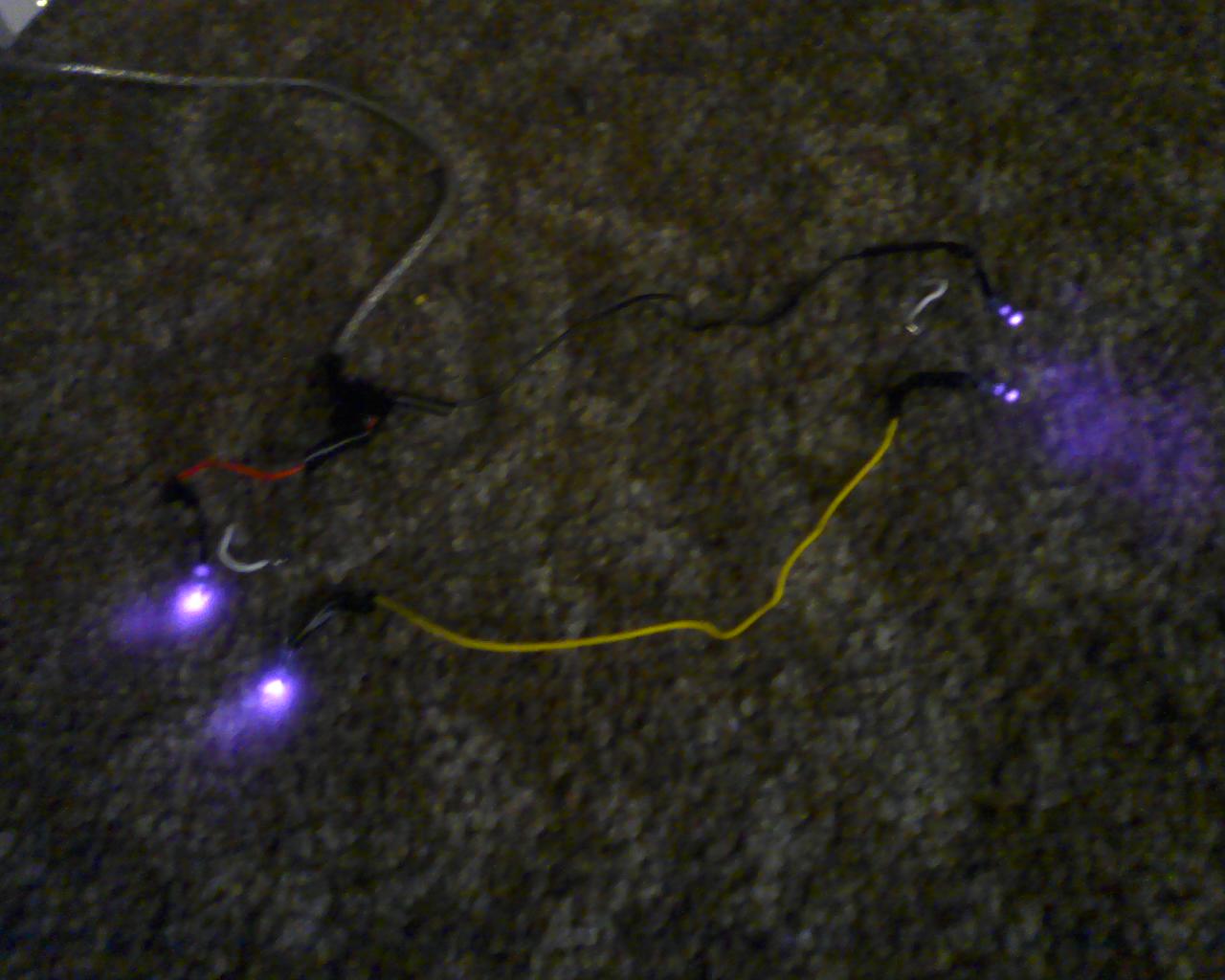
Now that all of the connections have been made it's time to test it before you fit it into your case.
Just plug it into any usb port while the device is on or that still provides power while in standby mode.
Use a camera or a phone or anything that takes pictures or video to make sure that the LEDS are lighting up (you can't see it with your own eyes).
Just plug it into any usb port while the device is on or that still provides power while in standby mode.
Use a camera or a phone or anything that takes pictures or video to make sure that the LEDS are lighting up (you can't see it with your own eyes).
Choosing a Case

When choosing a case to use for your sensor bar, make sure that the center of the LED placements are in line with the two on the Wii's sensor bar.
If you are not interested in making one out of Legos, simply skip to the last step.
If you are not interested in making one out of Legos, simply skip to the last step.
The Base of the Sensor Bar
For the base of my lego sensor bar I connected two 4x12 flat pieces with another flat 4x12 piece and a flat 4x6 piece.
The Wall of the Sensor Bar

I used 1x pieces to create the walls of the sensor bar and two 2x4 pieces with 2 flat 1x2 pieces snapped on the ends of it to hold the LEDs.
Placing in the Components
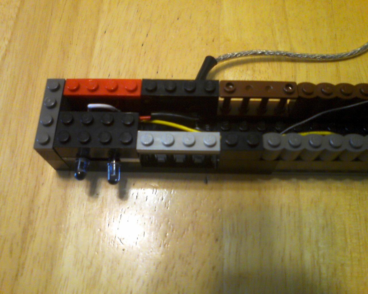
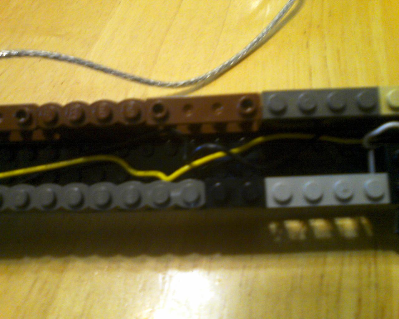

I placed the components in and put 2x4 blocks over the LED leads to keep them into place. I also twisted the wires to keep them from sticking out of the top.
Make sure the LEDs are close enough to each other and far enough apart.
Make sure the LEDs are close enough to each other and far enough apart.
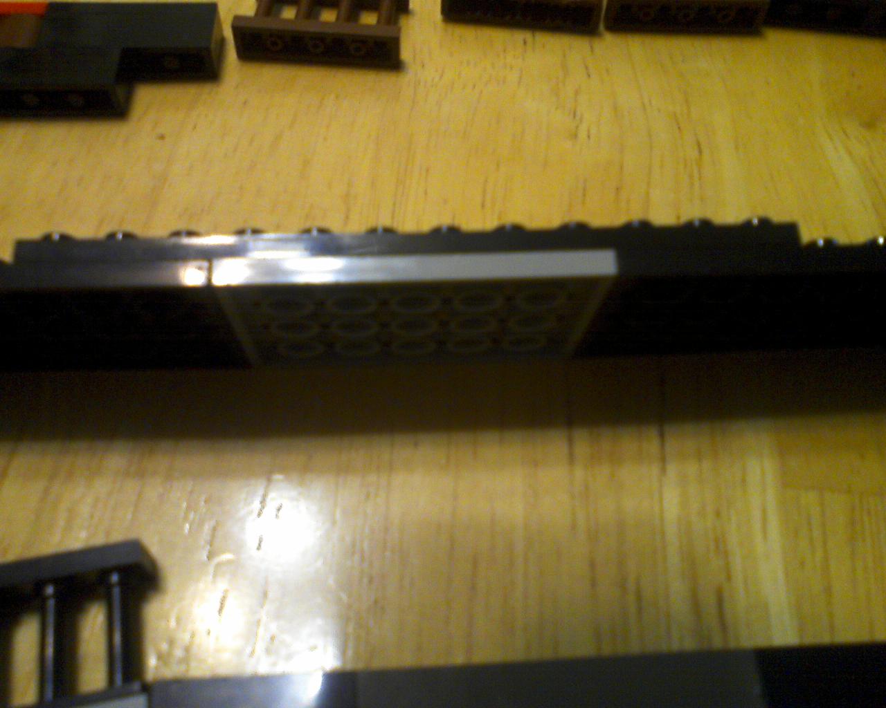
The Flaps


I made two flaps to cover the LEDs using two flat 4x6 pieces crisscrossed and adding a bendable flap.
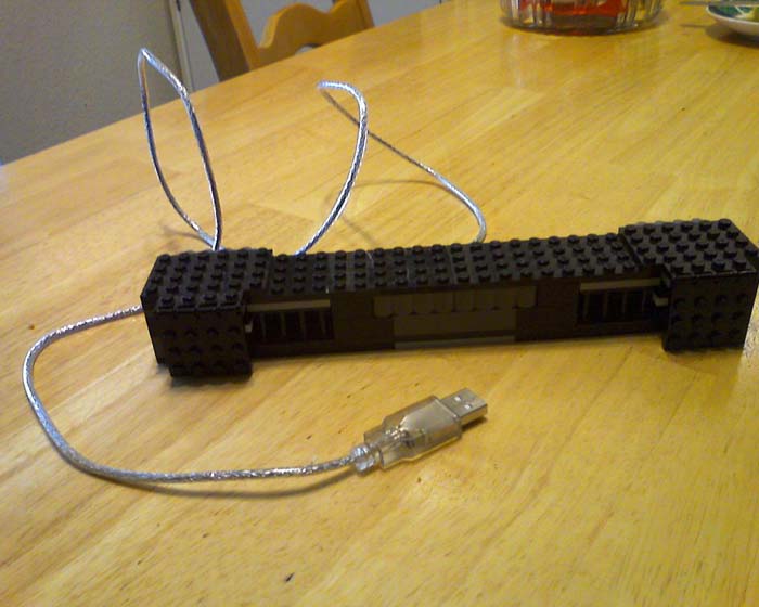
The Finished Case.
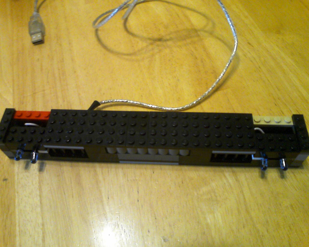


I Added two flat 1x4 pieces on each end, two flat 4x8 pieces 4 spots away from the end pieces, and filled the middle gap with a flat 2x4 piece.
The spots above the LEDs were filled with the flaps made in the last step.
The spots above the LEDs were filled with the flaps made in the last step.
Testing the Final Product

The last thing to do is to plug in your new sensor bar and make sure it works!