Underwater Marine Life/Flounder Light to Illuminate the Ocean Floor
by reckonill in Outside > Fishing
420 Views, 1 Favorites, 0 Comments
Underwater Marine Life/Flounder Light to Illuminate the Ocean Floor
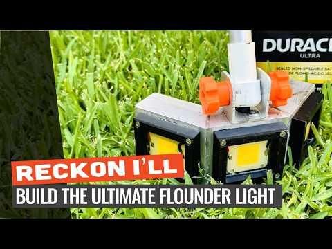
If you’ve ever been flounder gigging in the saltwater shallows, you know a good flounder light is essential. You need a high-powered light that can light up the entire ocean floor and it has to be waterproof.
This build uses a 12 volt battery, a 6061 aluminum round tube pole, 16-2 marine gauge wire, and a metal-detector-style wrist cuff and handle (designed on Fusion 360) to build the ultimate flounder light.
If you want to see more of my outdoor builds, you can check out my other work over at Reckon I'll Outdoors or subscribe to my YouTube channel.
Disclaimer: This project is presented for educational and demonstration purposes only. Any modifications, alternative material selections, or use of this guide for your own builds are done entirely at your own risk. Always follow safety precautions when working with power tools or customized equipment.
Supplies
Note: Some of the links below may be affiliate links. If you make a purchase through them, I may earn a small commission at no extra cost to you, which helps support future DIY builds!
Materials
- LED Chips: (3) 50W, 12V LED chips
- 12V, 18Ah Battery
- 16-2 Marine gauge wire
- 12-2 Marine Gauge Wire
- Thermal Paste
- Toggle Switches (3)
- Parks/Varathane Super Glaze epoxy
- Wago Wire Connectors
- 1 in. Type LL PVC Conduit Body Conduit Fitting
- 1" to 3/4" Reducer Bushing
- 20amp Fuse with Holder
- Alumiweld Brazing Rods
- Cutting Board (if not 3D printing)
- M4 x 20mm Socket Hex Head Bolts (12)
- 1/4-20" 3/4" Bolts (2)
- Metal Detector Cuff
- 1/2 in. COMP x 1/2 in. COMP PVC Tee with 1/2 in. FIP Branch
- 1/2 in. PVC Schedule 40 Male MPT x S Adapter
- 1/2" PVC (~6")
- 3″ x 1.5″ Aluminum Rectangle Tube (3 pieces at 3.5" with 22.5deg bevels)
- 2" x 1.5" Aluminum Rectangle Tube (for hinge)
- 7/8" Aluminum Round Tube (for the main pole)
Tools
- Step Bits
- MAP Gas
- Trigger Start Torch
- Metric Taps
- Welding Gloves
- 1" Hole Saw (or use step bits)
- Angle Grinder
- Heat Gun
- Soldering Iron
- Bambu Labs P1S 3D Printer (Optional)
- Bambu Labs PETG Basic (Optional)
Autodesk Fusion 360 created 3D Prints
Prep and Cut the Aluminum Housing
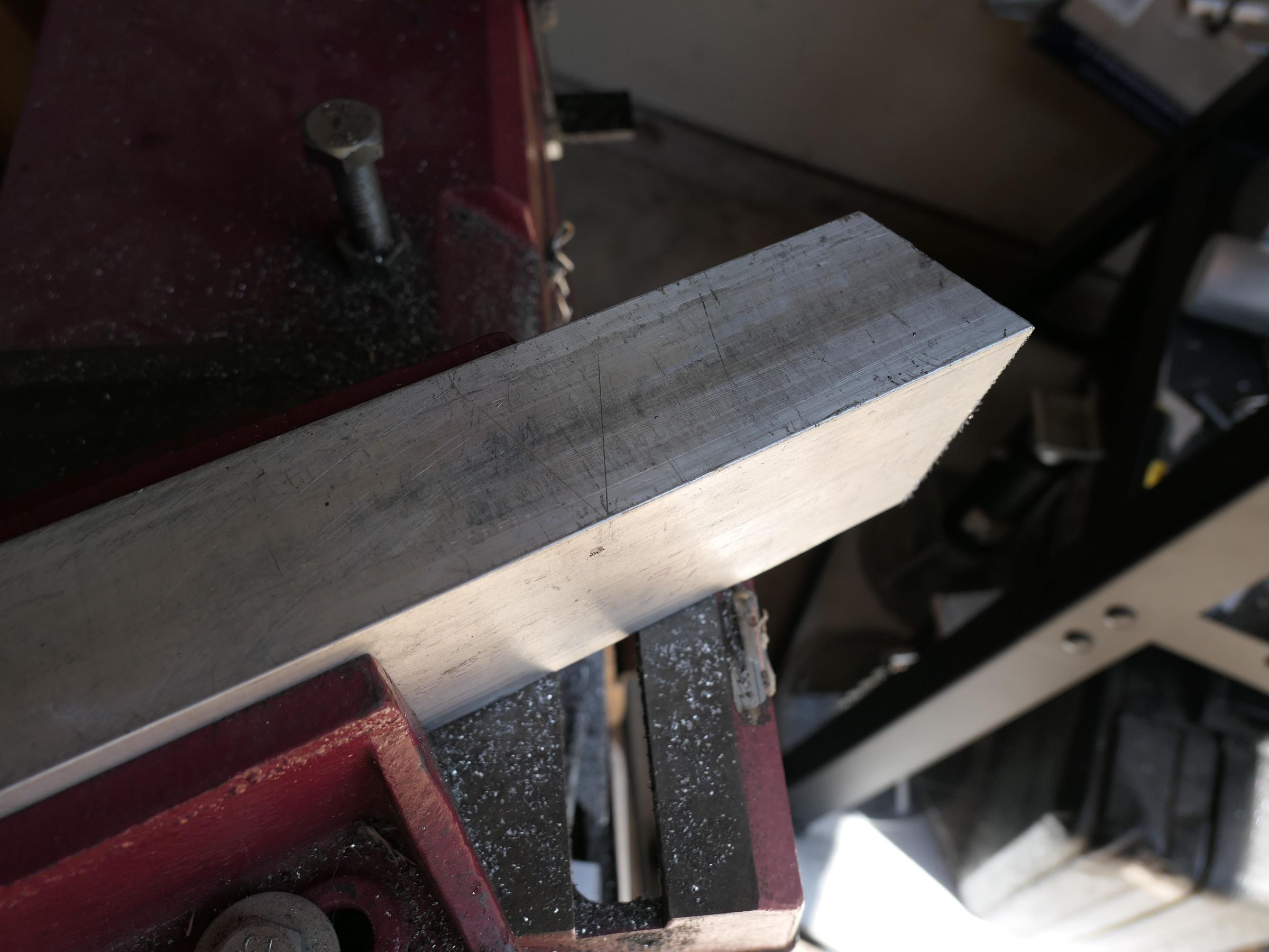
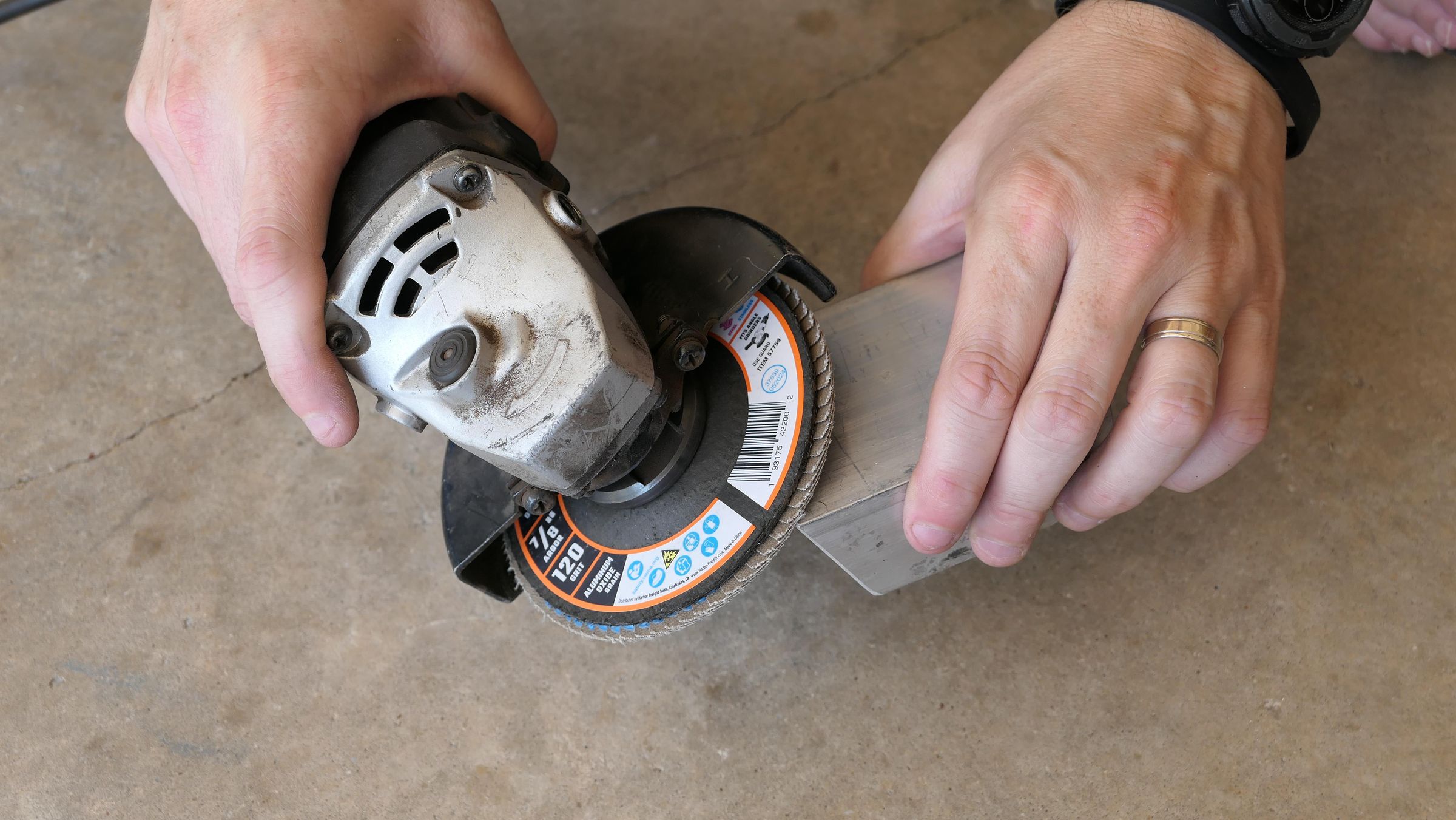
Cut three 3.5-inch pieces of your 3-inch x 1.5-inch aluminum rectangle tube to build the light head. Scribe and cut 22.5-degree miters on the connecting ends. Keep the outside edges of the two side pieces completely square.
Bevel the edge of each piece so it will have a nice channel when you braze it later.
Fabricate the Epoxy Surround Frames
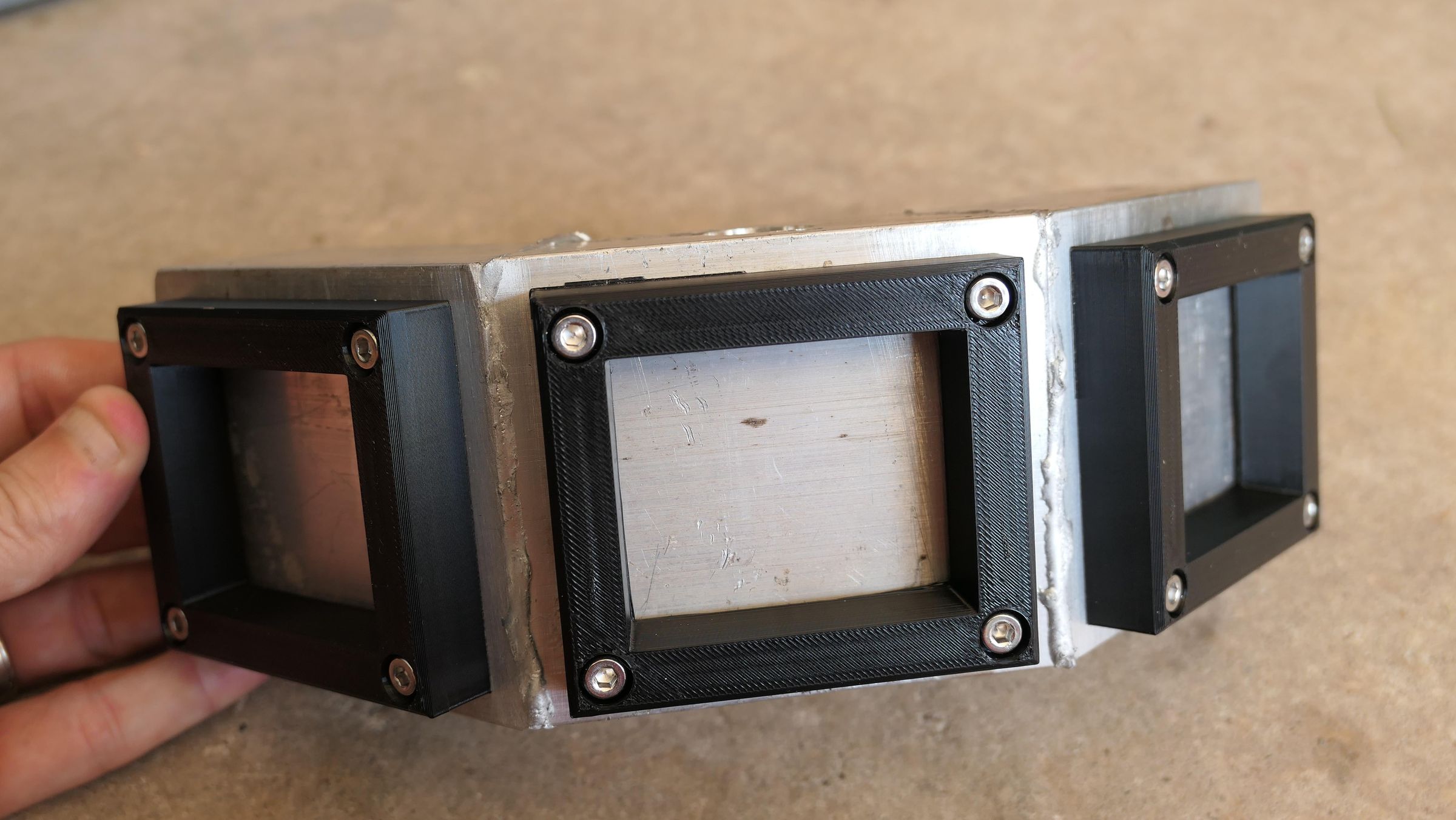
Create a raised border on each face of the aluminum housing to pool and hold the waterproofing epoxy over your LED chips. You can either 3D print custom frames I designed in Fusion 360 out of ABS filament or use a jigsaw to cut matching square borders out of a cheap HDPE plastic cutting board.
Drill and Tap Frame Mounting Holes
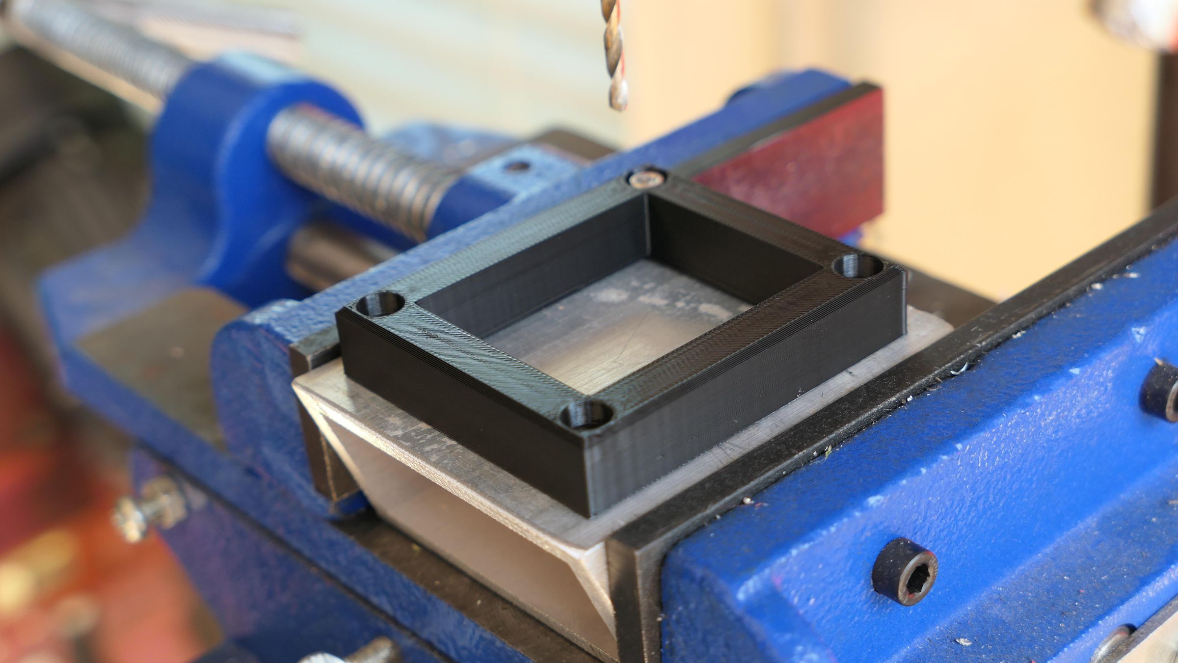
Position your newly fabricated epoxy surround frames onto their respective aluminum tube sections. Drill and tap mounting holes directly into the aluminum face.
Remove the plastic or 3D-printed frames after tapping and set them aside so they do not melt during the brazing process.
Drill the Wiring Access Hole
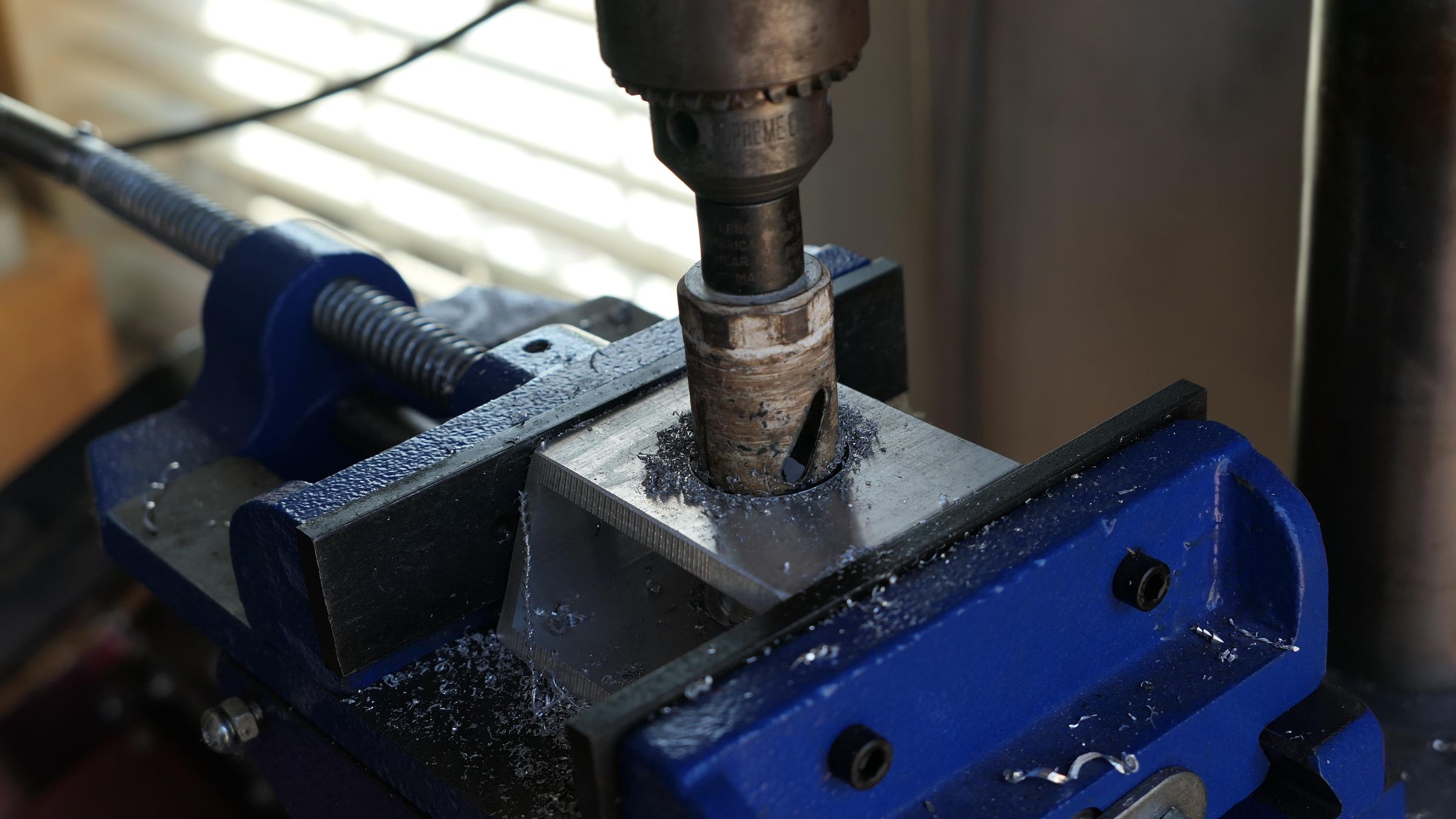
Drill a 1-inch wiring access hole into the back wall of the middle housing section. Doing this on the drill press while the middle piece is still separate and easy to clamp ensures a clean, centered cut.
Cut and Drill the Hinge Bracket
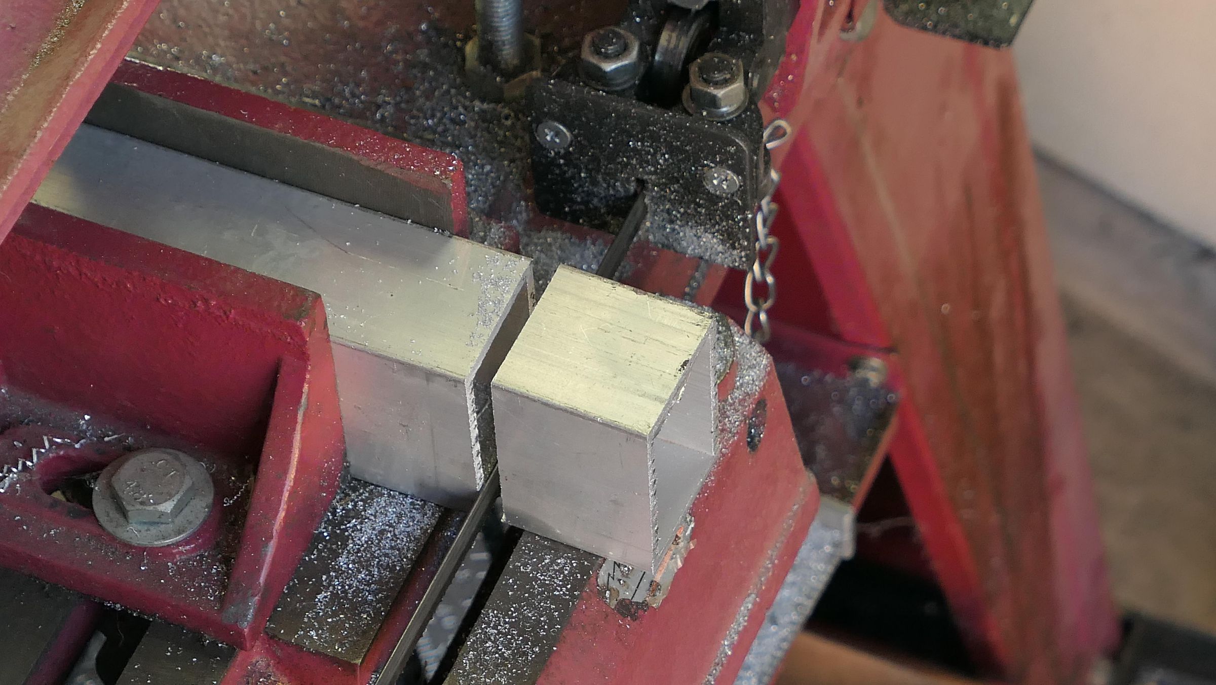
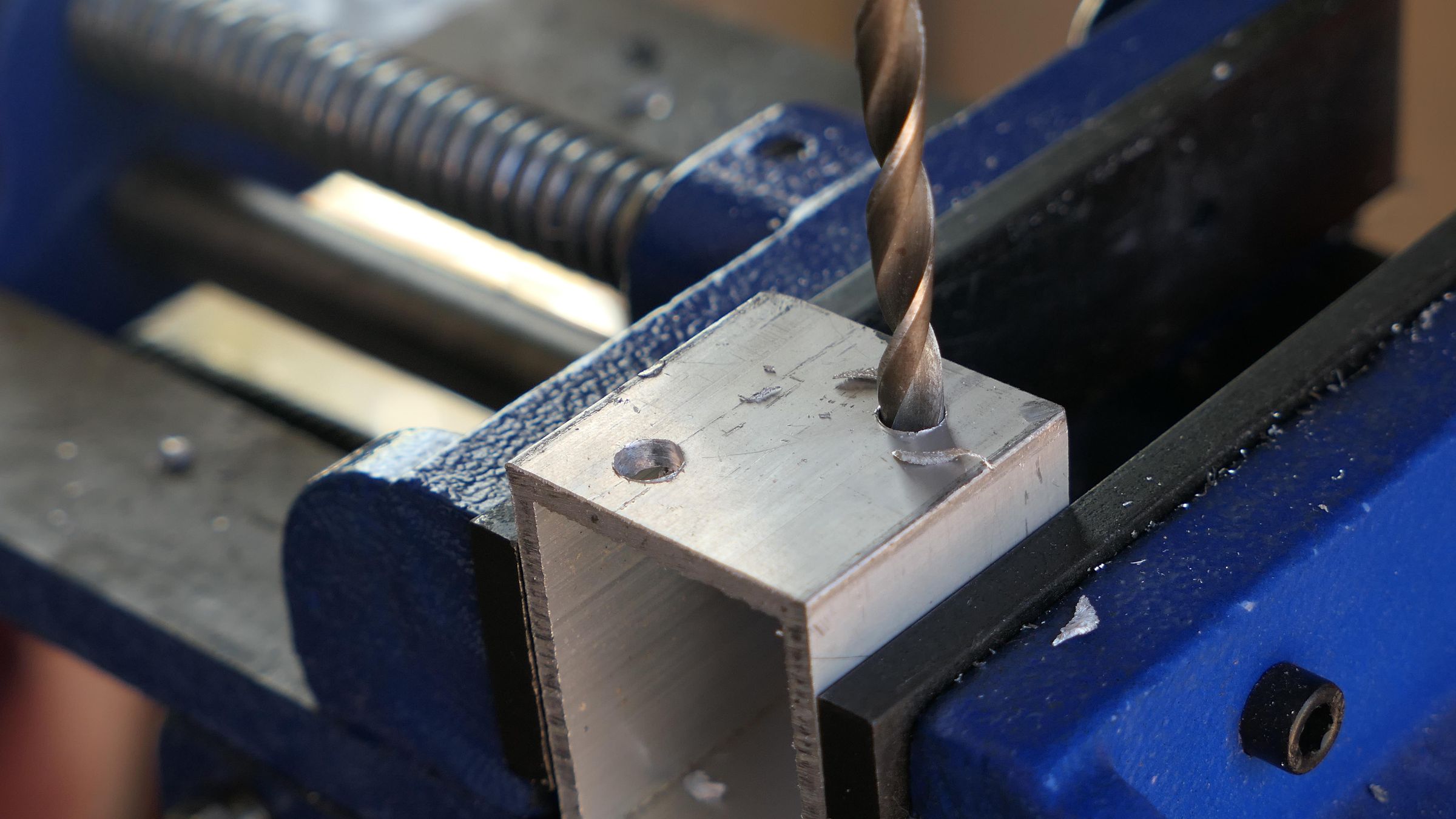
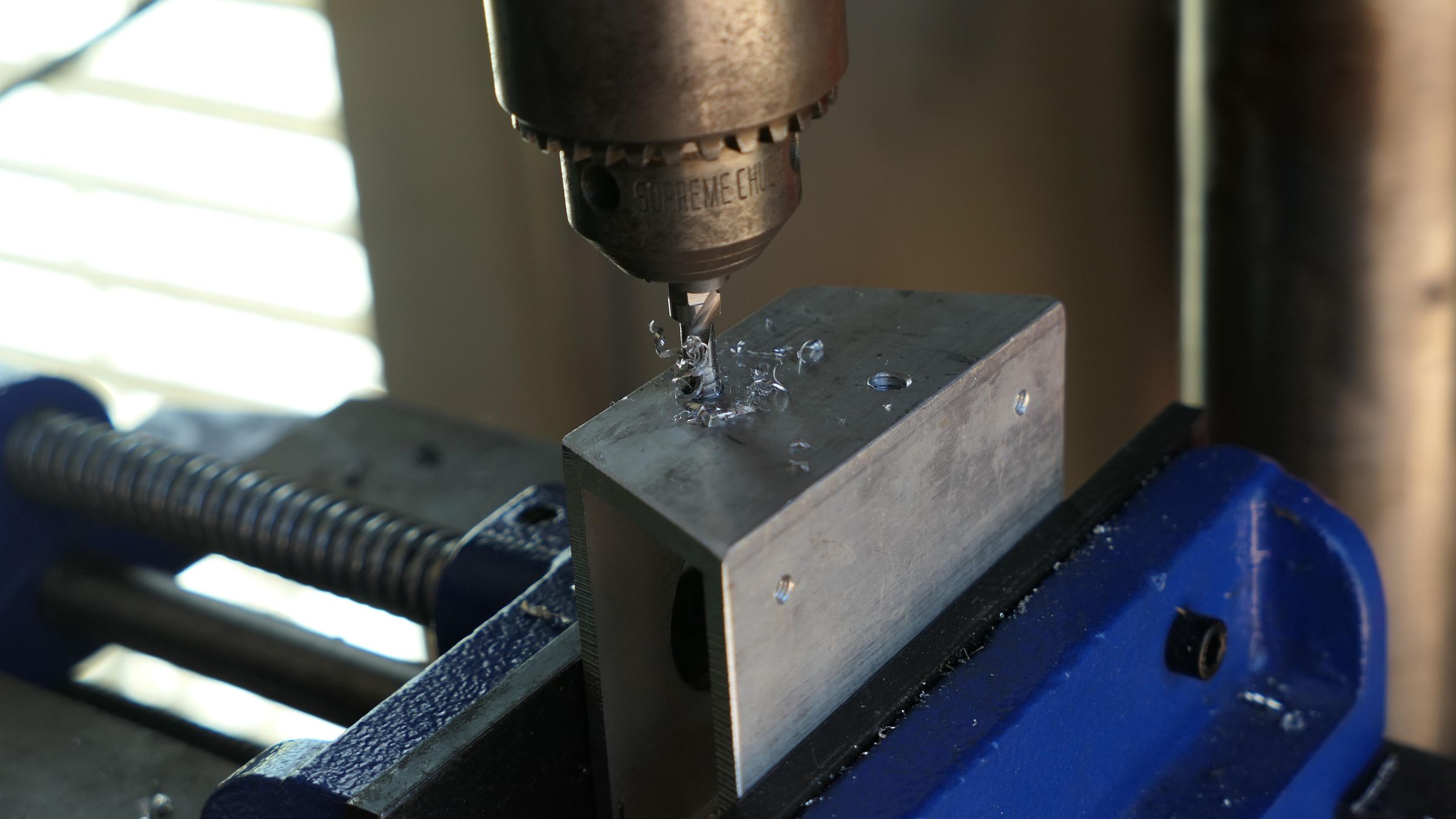
Cut a 1.5-inch section of 1.5" x 2" aluminum square tube. Drill two 1/4" holes through the bracket (one at a time) into the center housing and tap with 1/4-20 tap. These will be used to secure the bracket to the light housing.
Convert to a U-Bracket
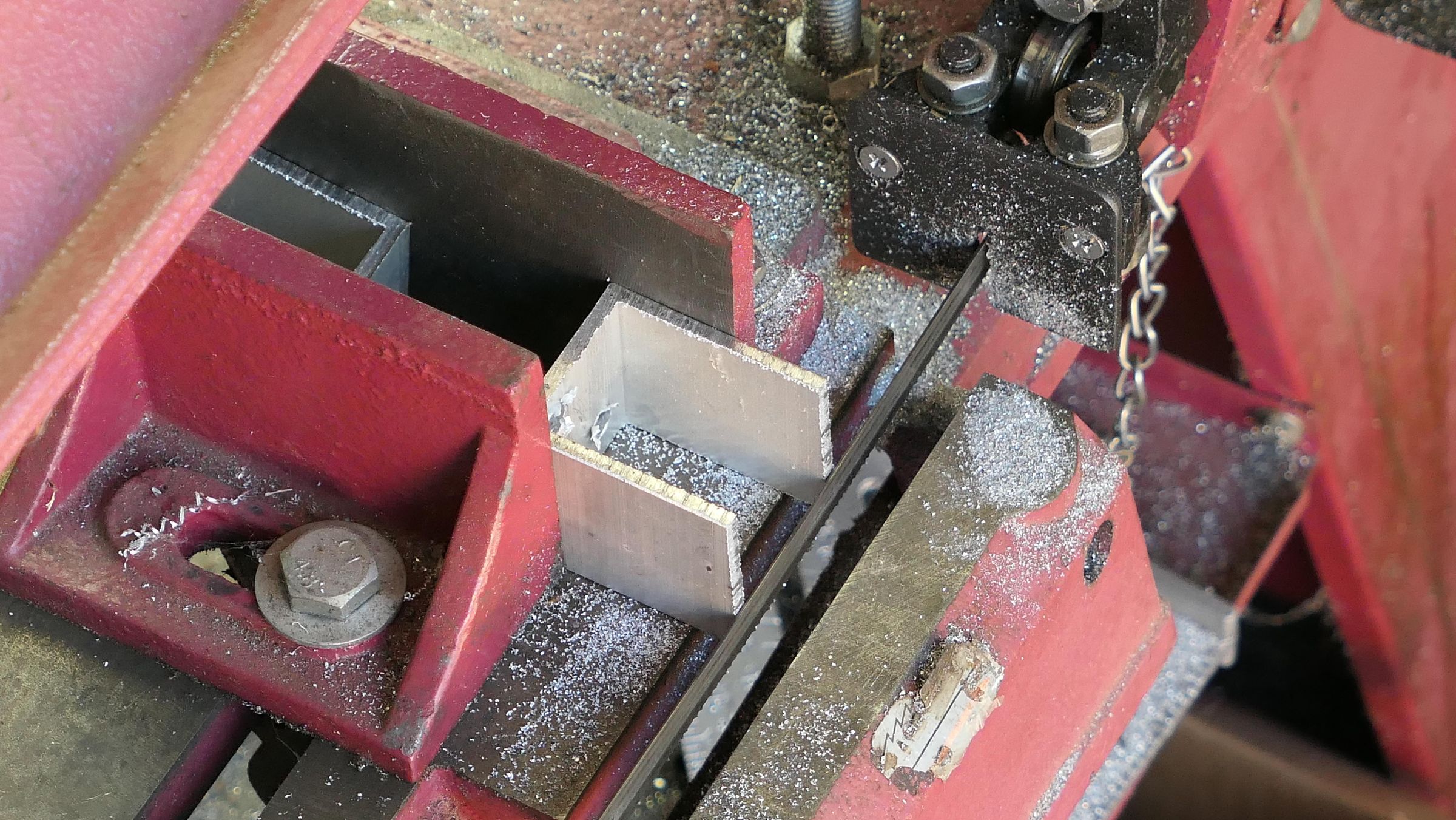
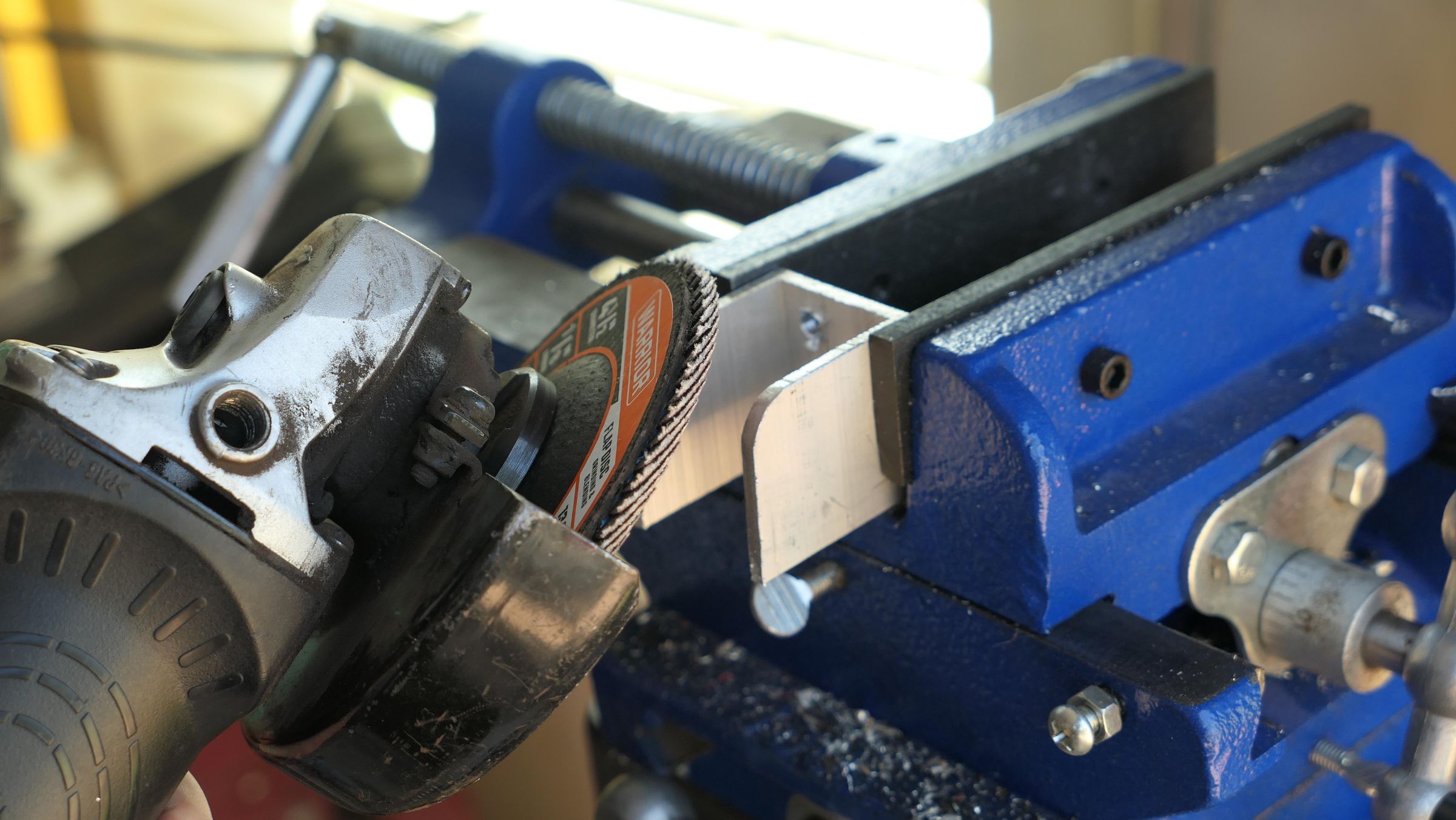
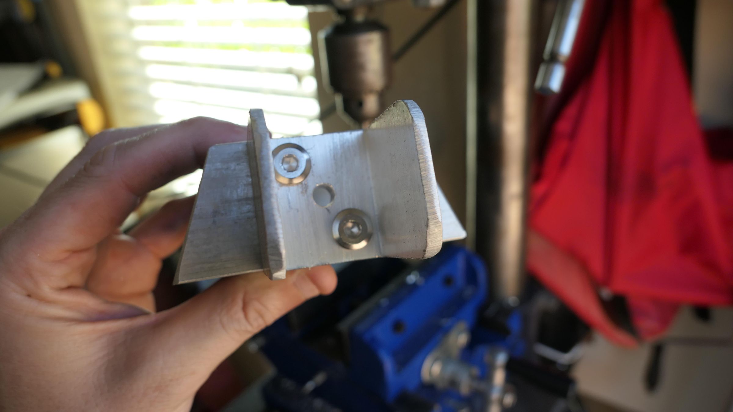
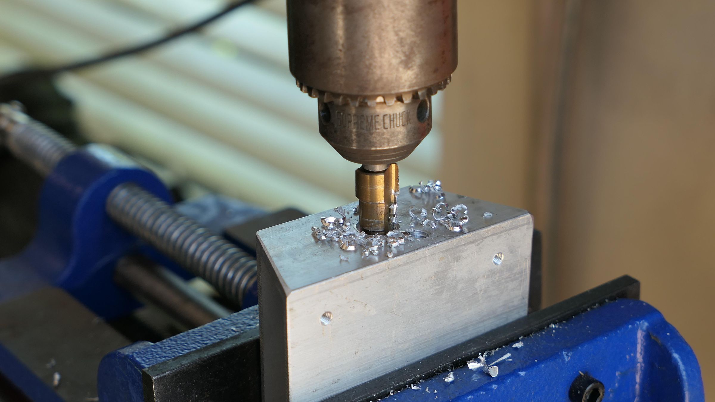
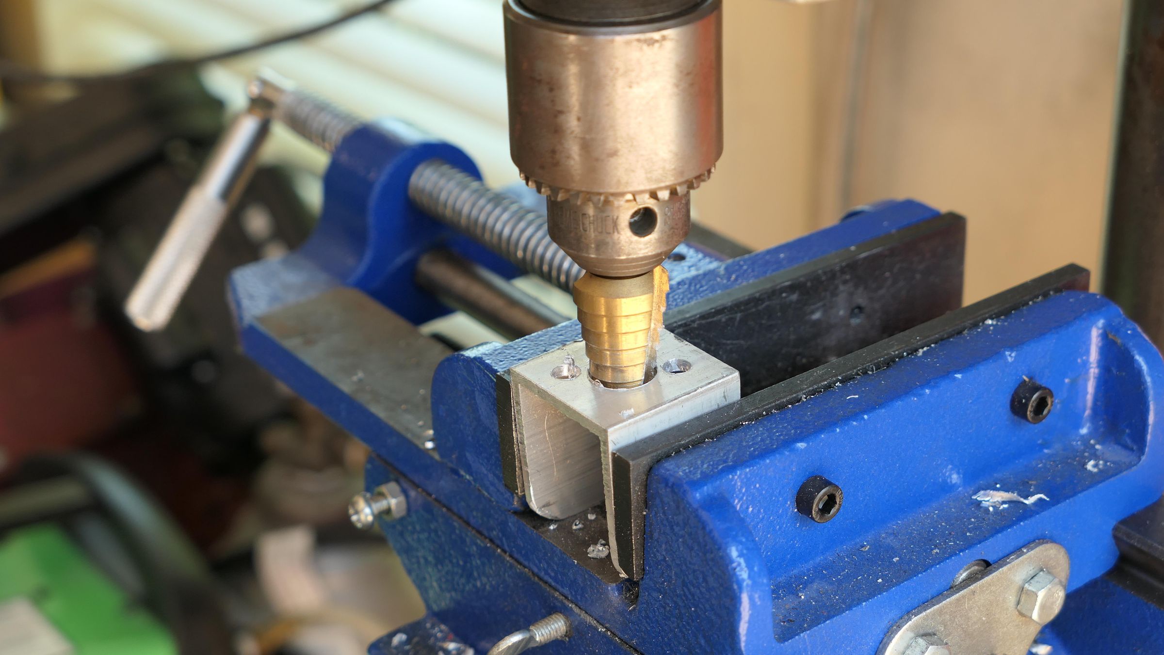
Remove one wall to create a rigid U-shaped bracket and round the edges with an angle grinder.
Secure the hinge using the 1/4" screws and then drill through the hinge and center housing stepping up to a 9/16-inch wire pass-through hole directly in the center of the hinge and through the middle housing.
Braze the Housing Together

Clamp the three mitered rectangle tubes together to form your final curved shape. Heat the aluminum joints with a MAP gas torch and apply aluminum brazing rods to seal the seams. Let the welded metal cool completely to room temperature before handling.
Reattach the Epoxy Surround Frames
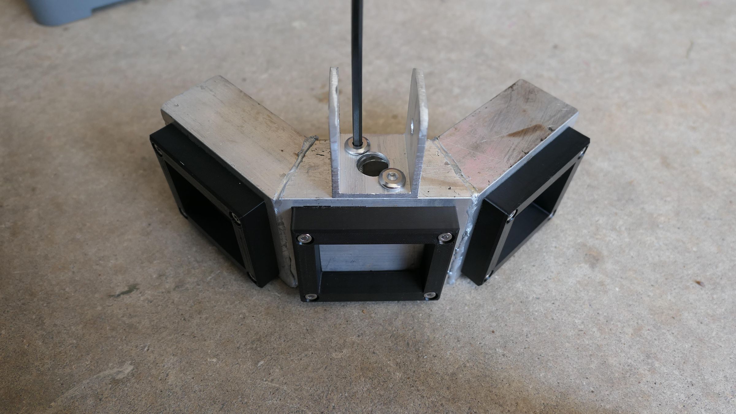
Align your plastic or 3D-printed ABS surround frames over the cooled, brazed aluminum housing. Fasten them back in place by driving stainless steel screws directly into the pre-tapped holes you made in Step 3.
Drill the Hinge
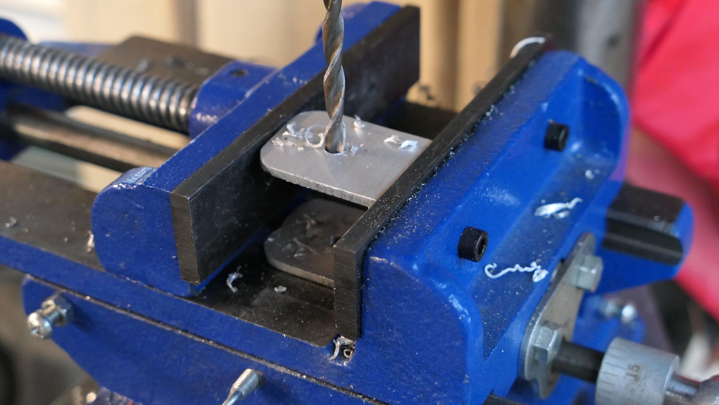
Drill a 1/4-inch through-hole off-center towards the rounded top of the aluminum hinge.
Drill COB Wiring Holes
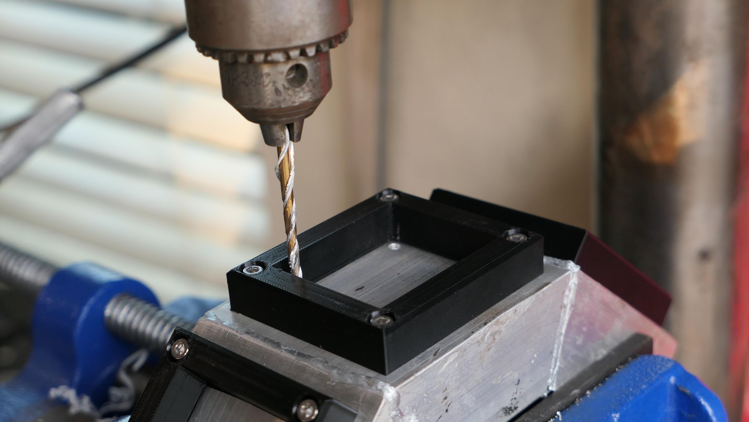
Drill a 1/8-inch hole in the top right and left corners of each surround frame to be used for wiring in the future.
Attach the Top Hinge
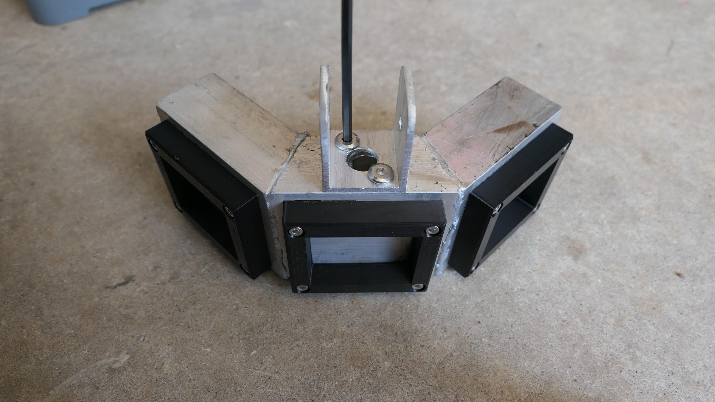
Using 3/4" 1/4-20 bolts, attach the finished hinge bracket to the top of the middle housing.
Attach the Cuff & Handle
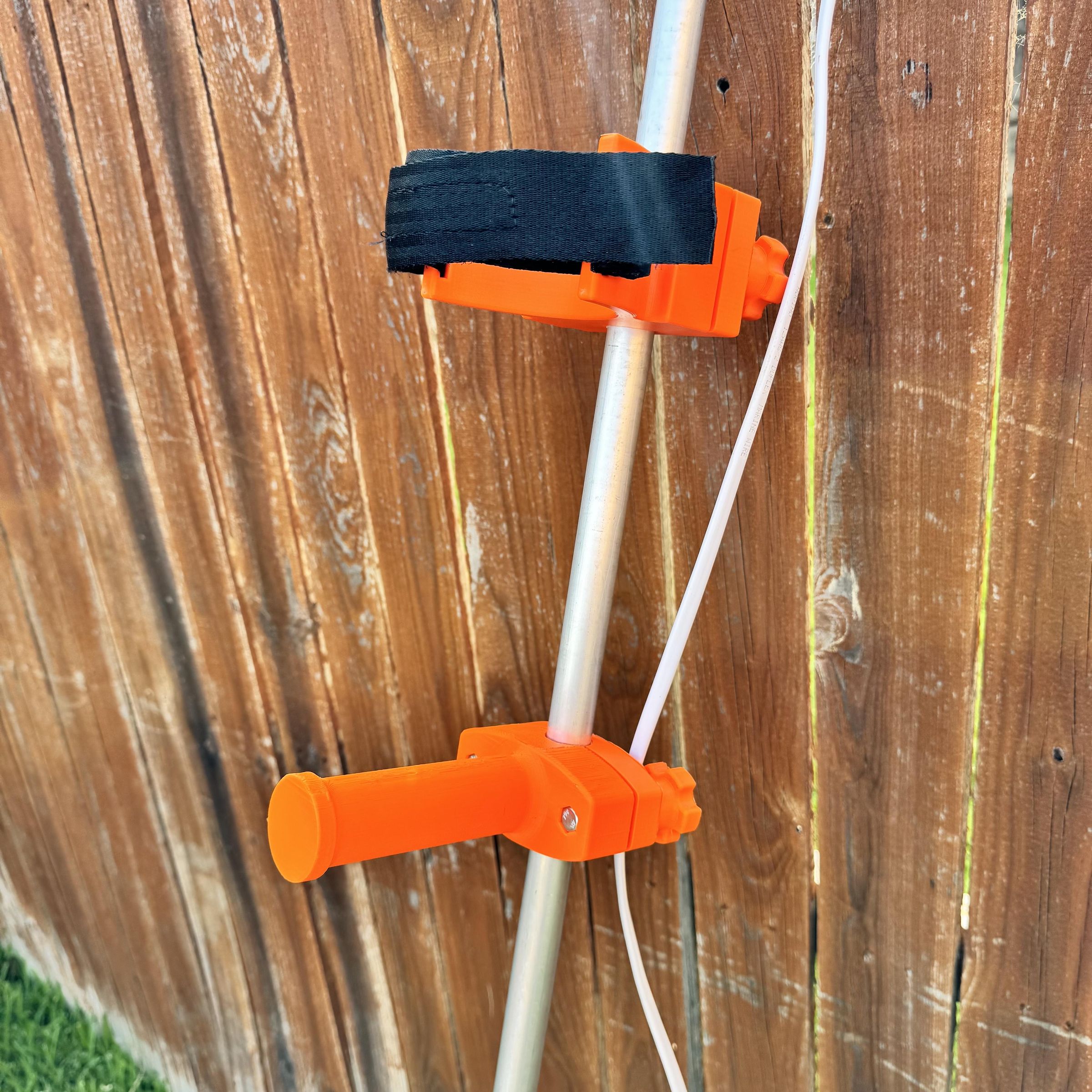
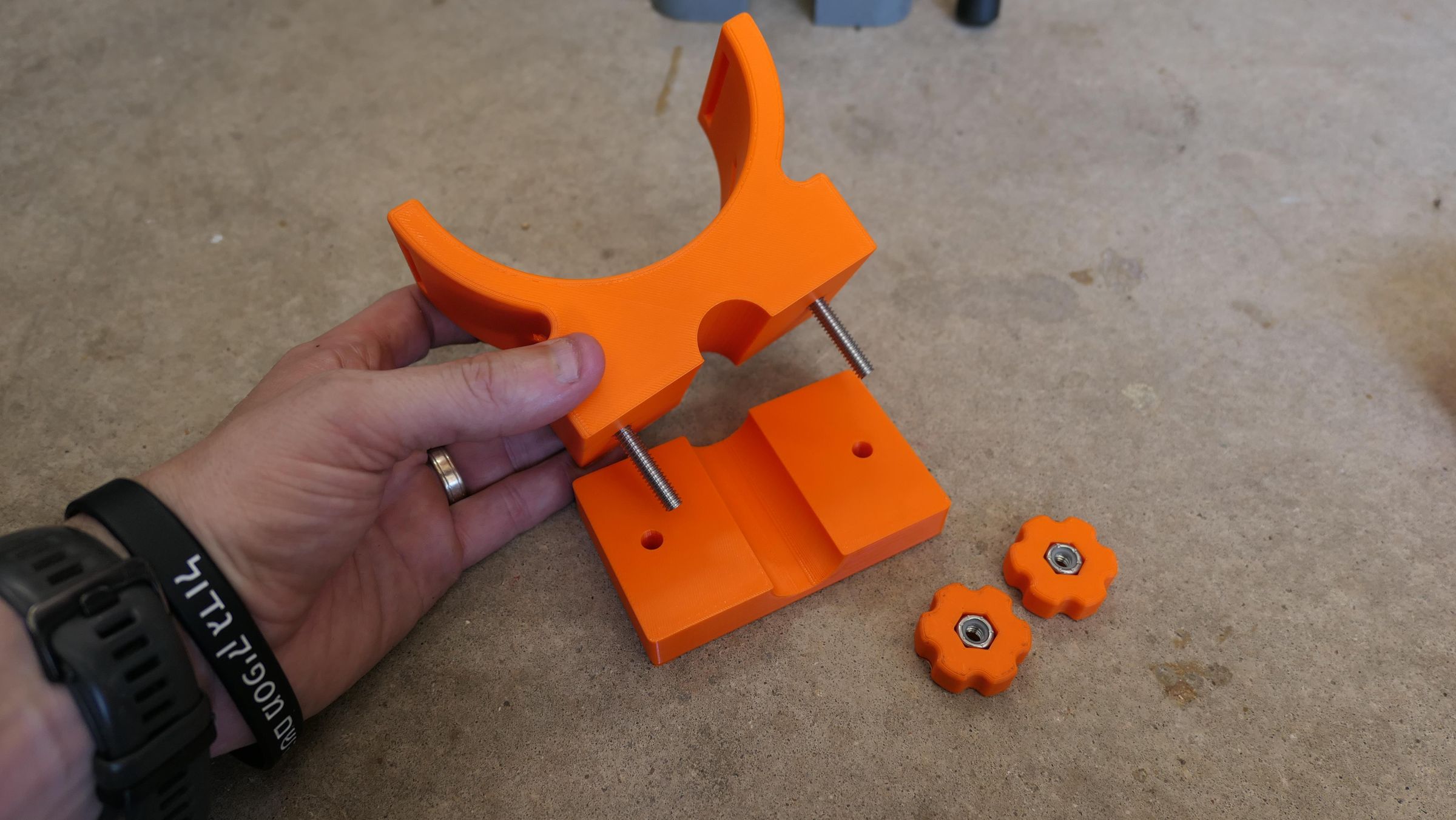
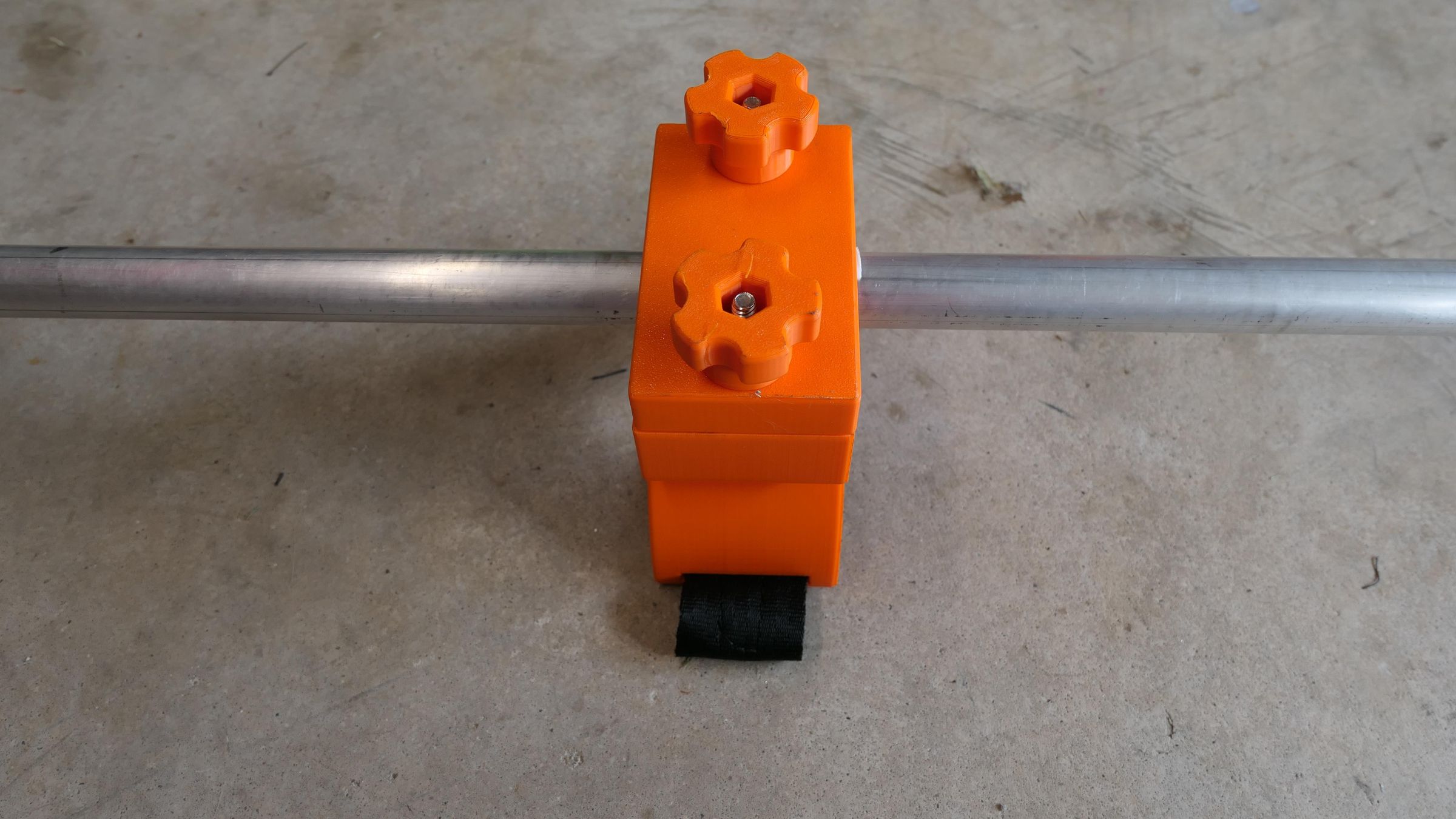
Attach your cuff and handle assemblies onto the raw tube. You can use 3D-printed PETG/TPU parts secured with a 1/4-20 x 2.5-inch bolt, or build a hardware store version using an off-the-shelf metal detector cuff and a modified 1/2-inch PVC compression tee.
Sleeve the Top (Enclosure) End of the Pole
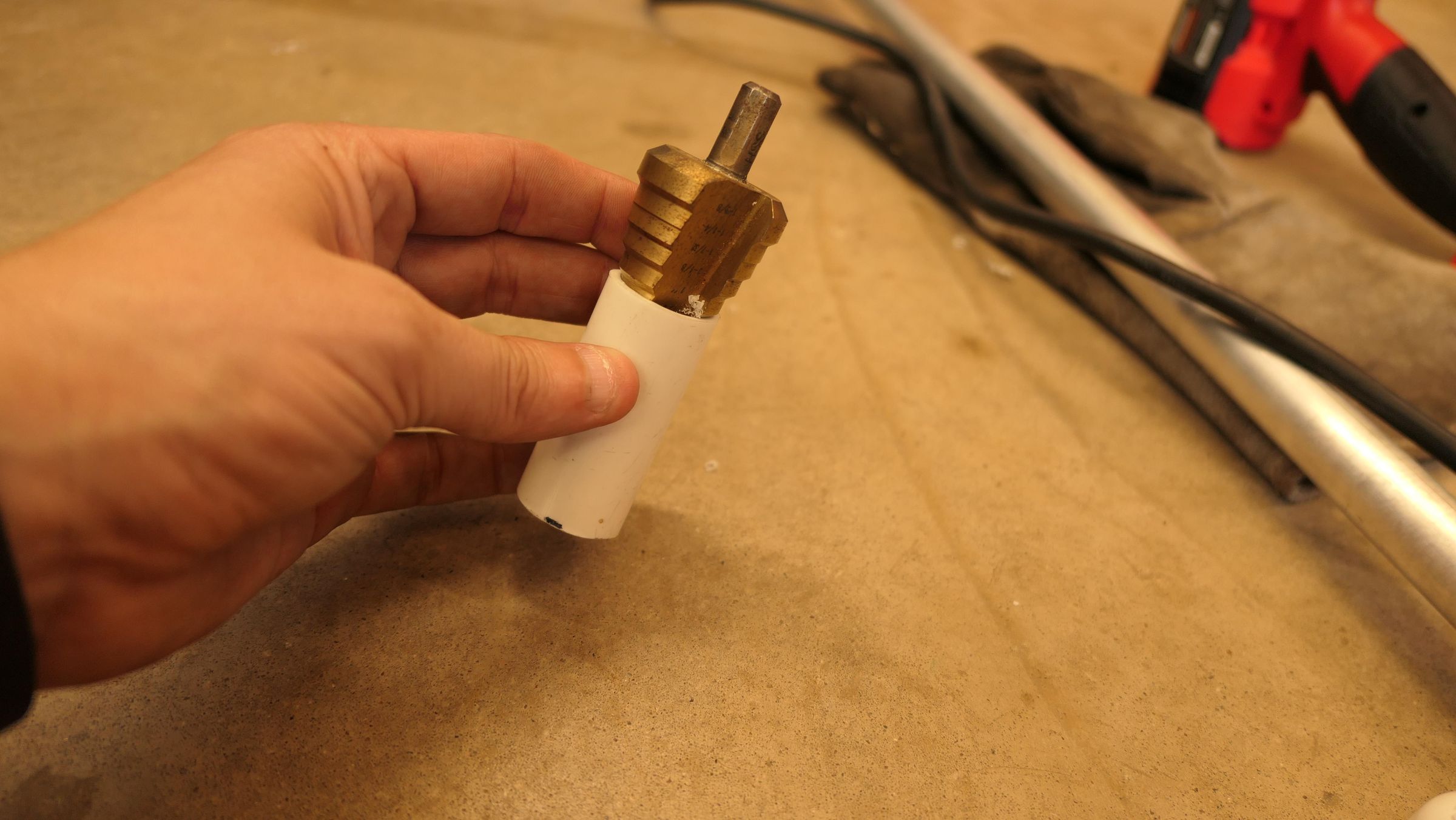
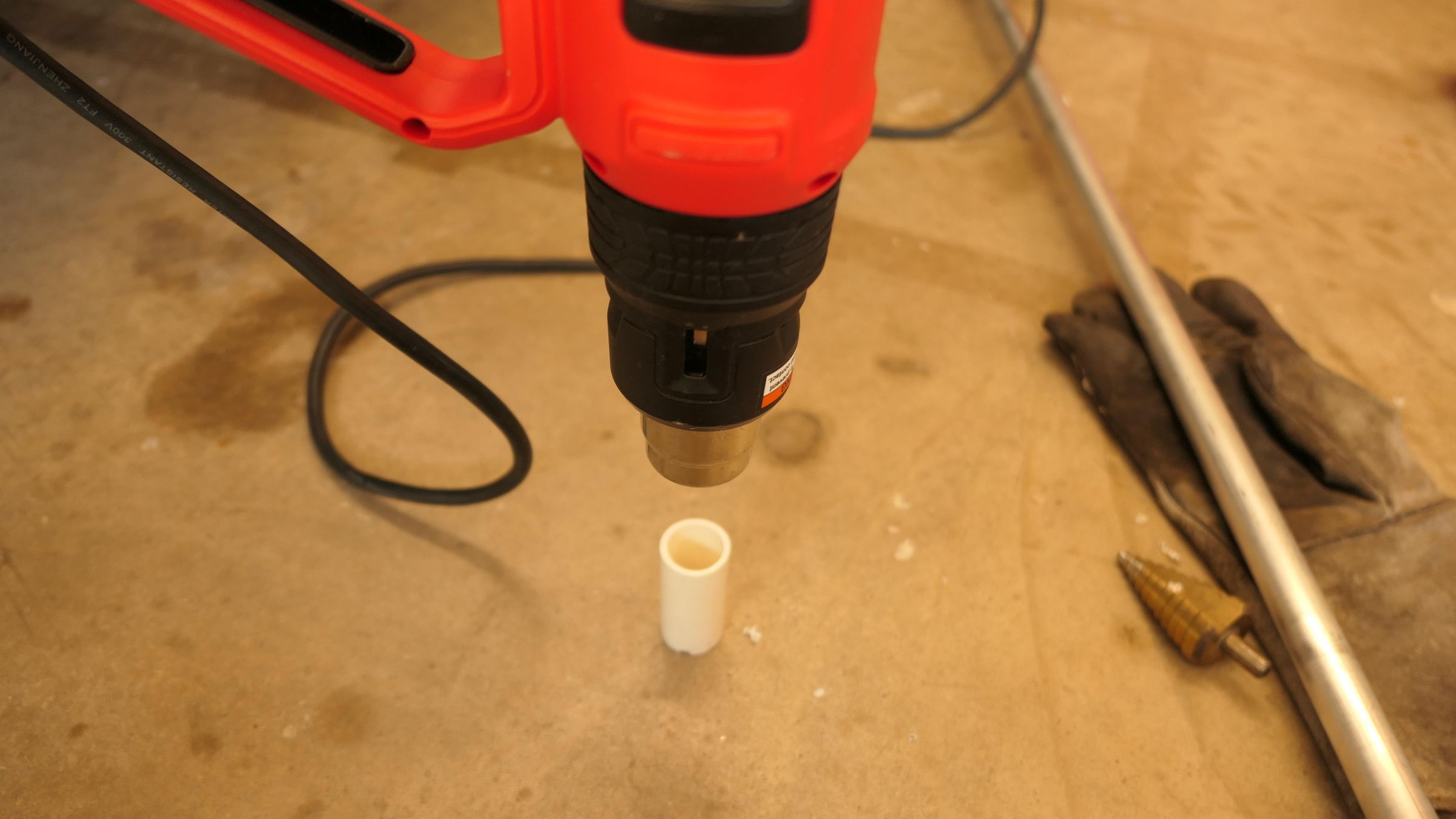
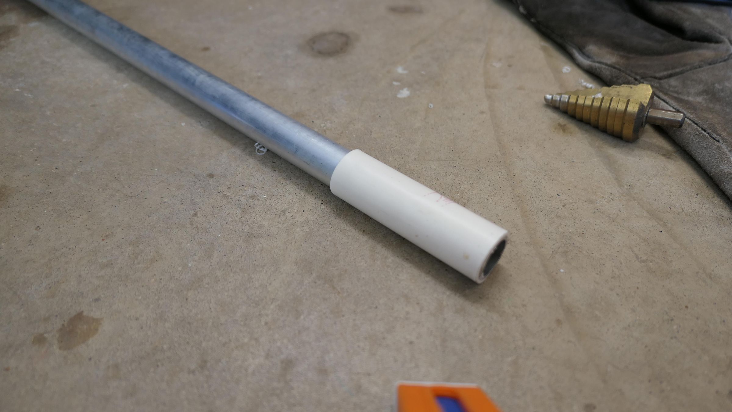
Cut a 3.5-inch sleeve of standard 3/4-inch PVC pipe and chamfer the inside edge with a step bit. Use a heat gun to gently soften the PVC, then drive the top end of your 7/8-inch aluminum pole into the sleeve until it is completely flush.
Sleeve and Cap the Hinge End of the Pole
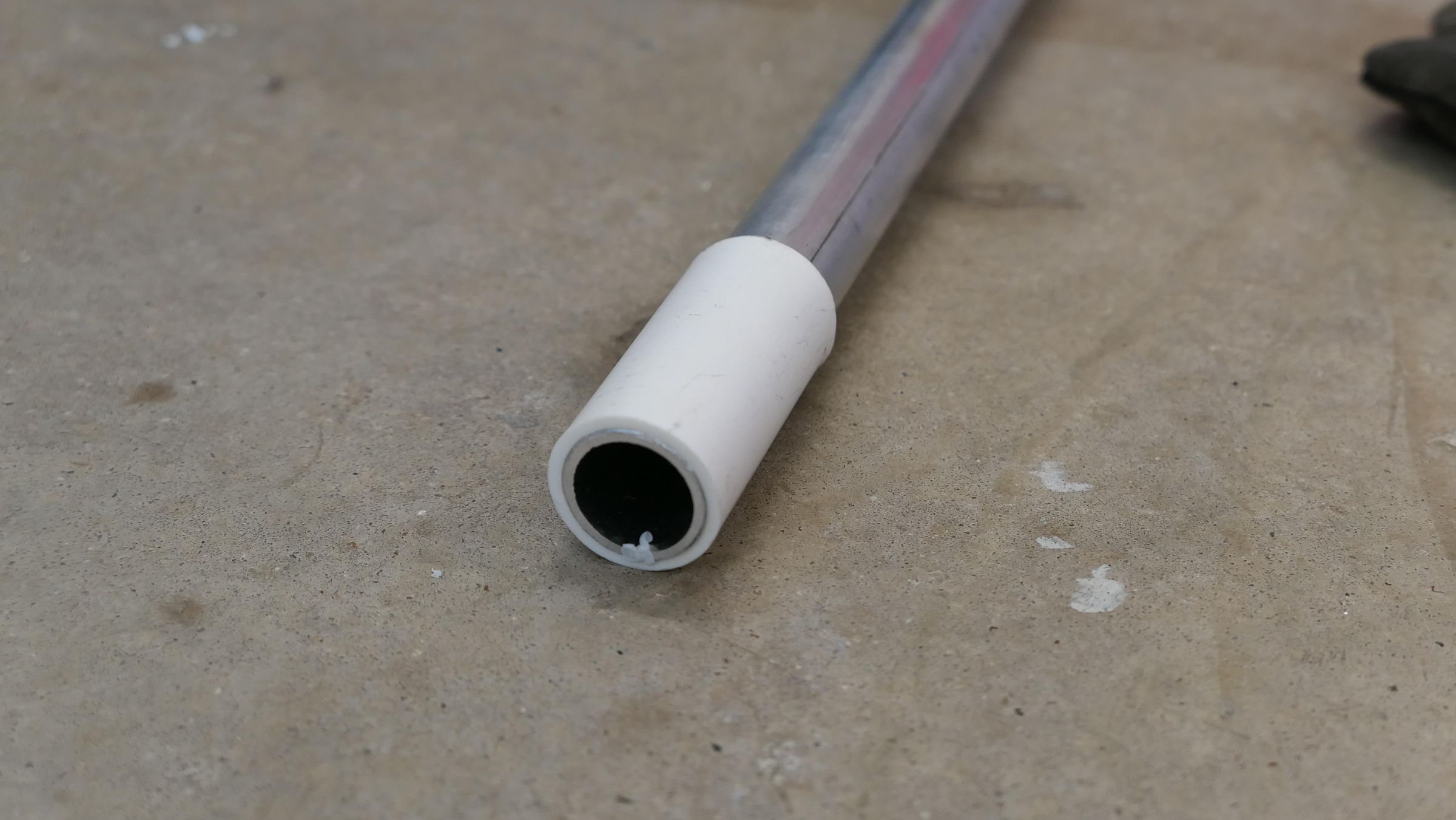
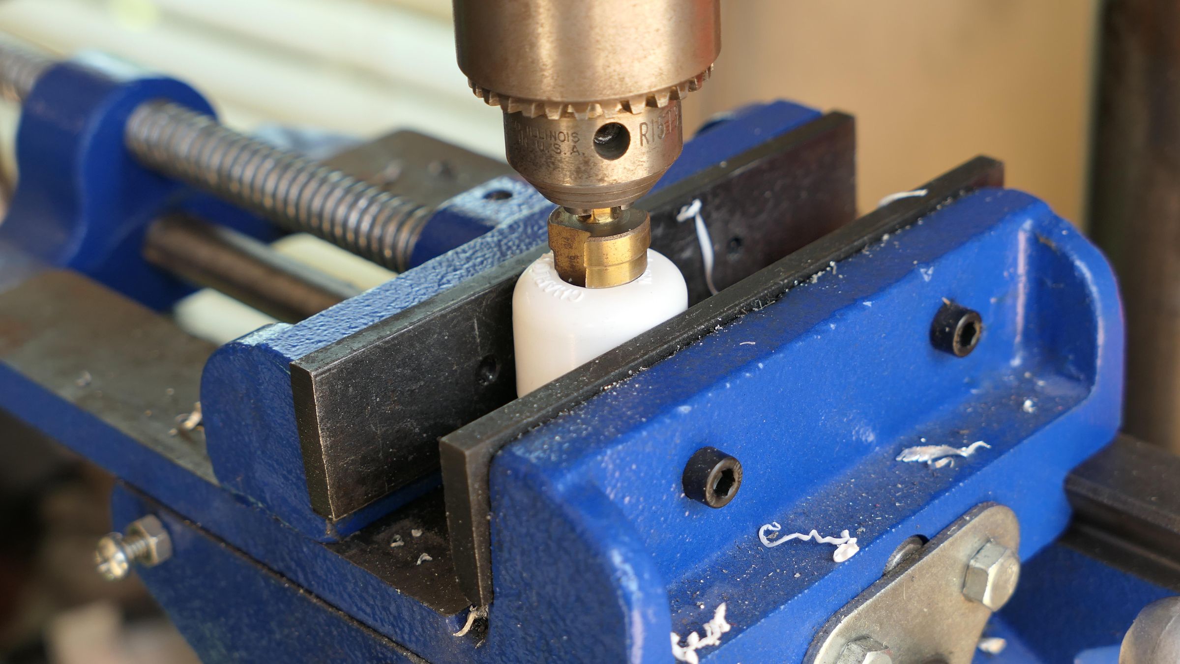
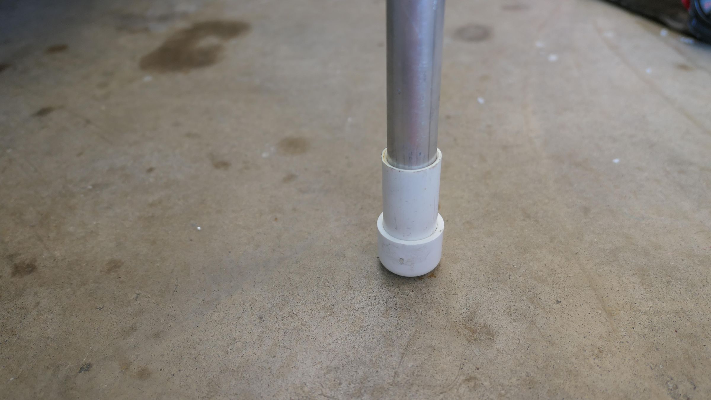
Cut a 2.5-inch sleeve of 3/4-inch PVC pipe, chamfer the inside, heat it, and drive the bottom end of the aluminum pole flush inside it. Next, drill a 5/8-inch hole into the center of a standard 3/4-inch PVC cap and drive this cap onto the 2.5-inch sleeve to seal the edge.
Drill Through the Capped Aluminum Pipe
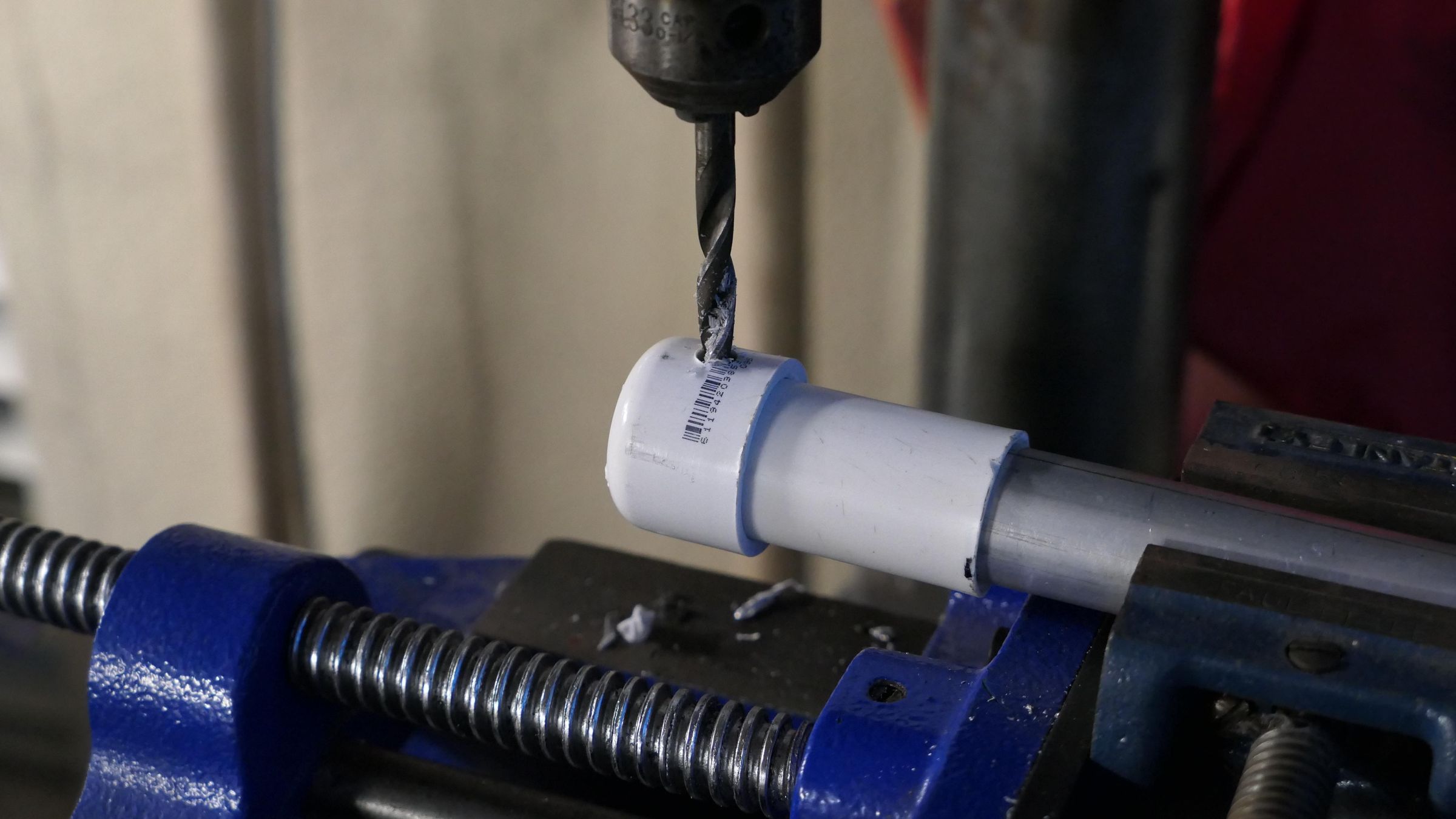
Drill a 1/4-inch through-hole straight through the newly installed PVC cap, the PVC sleeve, and the internal aluminum pole to accommodate the hinge bolt.
Test Fit Attaching the Housing
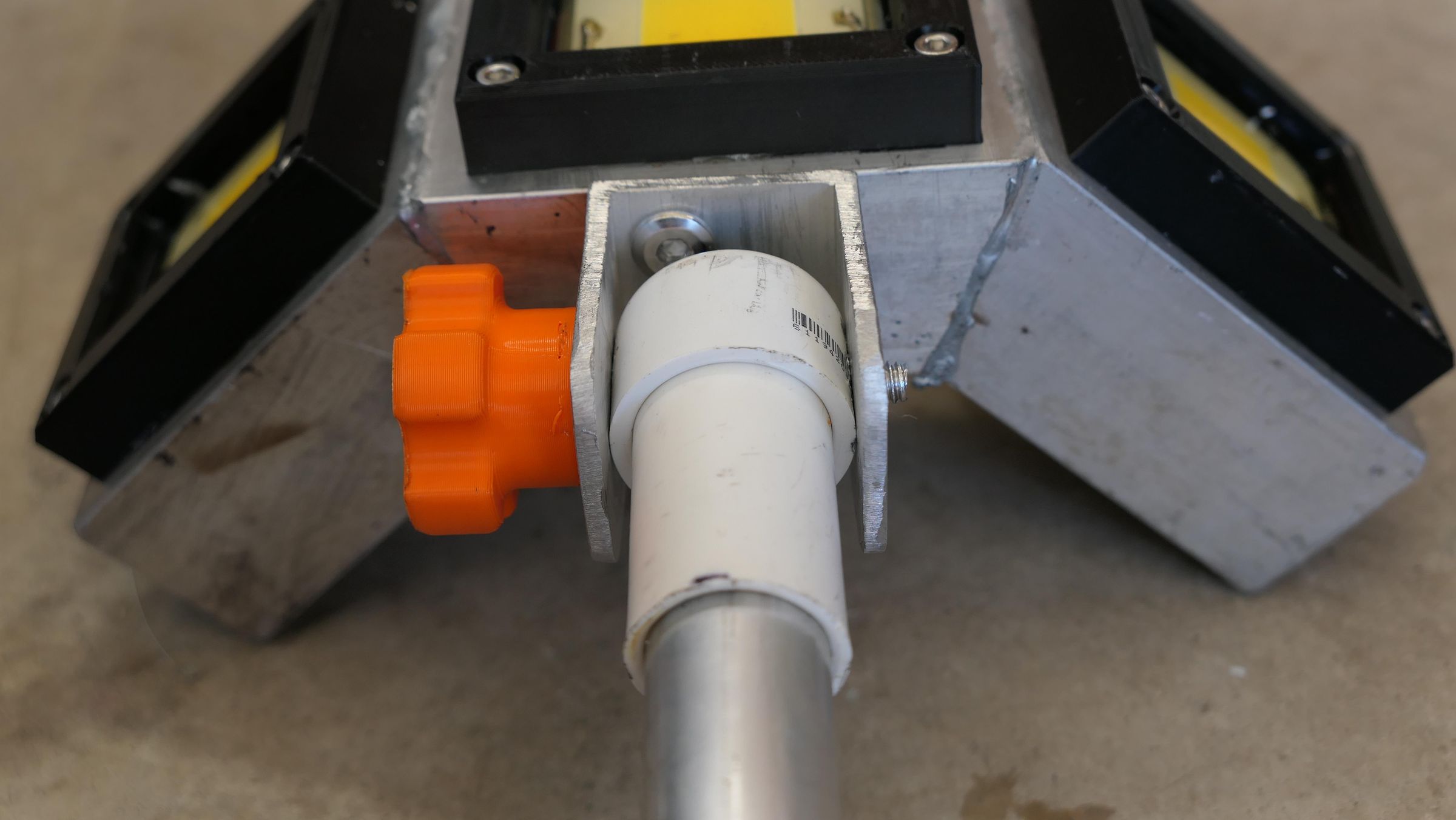
Secure the pole to the U-bracket using a 2.5" 1/4-20 bolt and a nyloc nut (or a 2" bolt with a wingnut). Loosening and tightening this hinge allows you to adjust the light head angle in the water without needing tools.
Route Wire and Solder the LED Chips
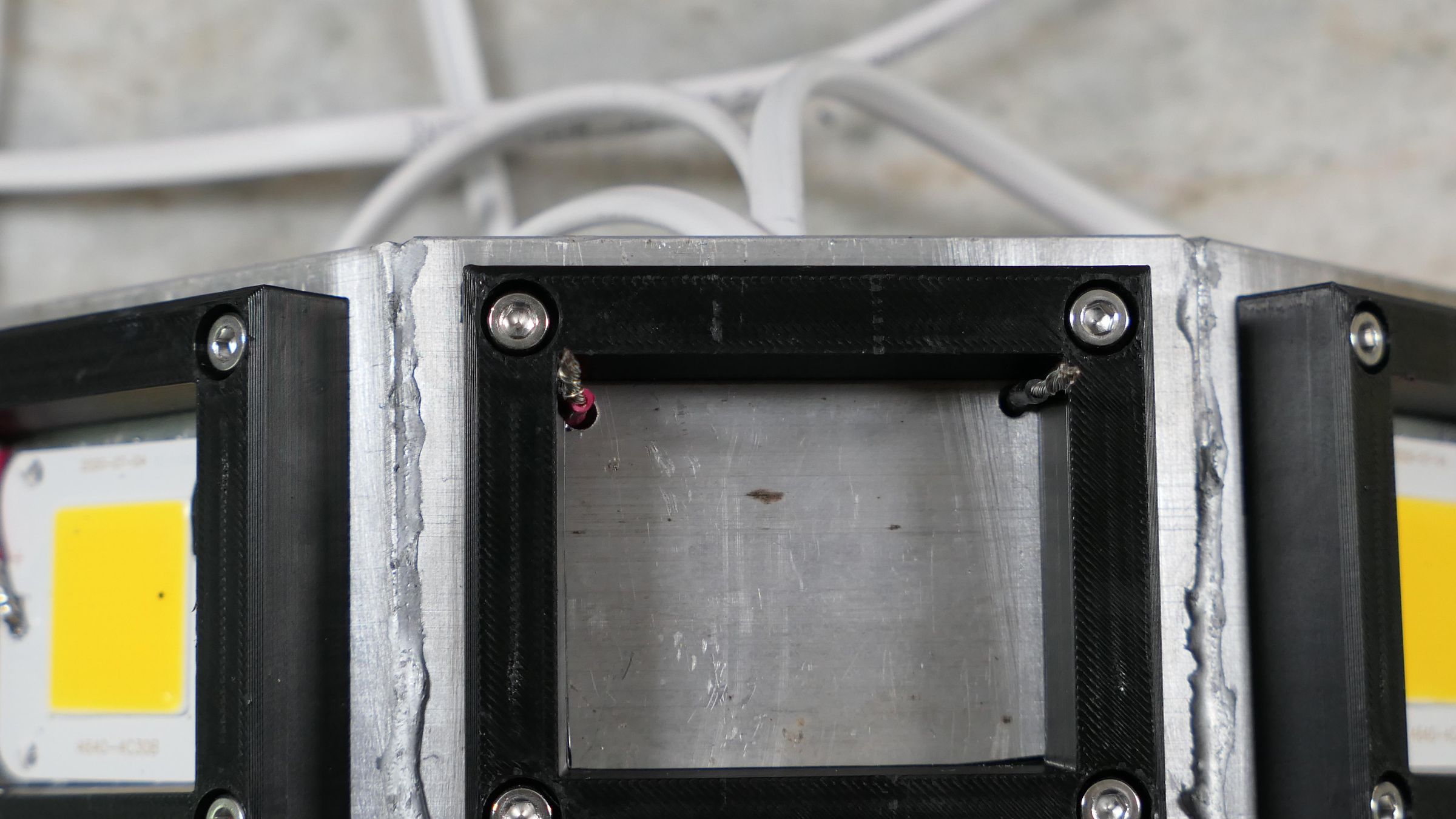
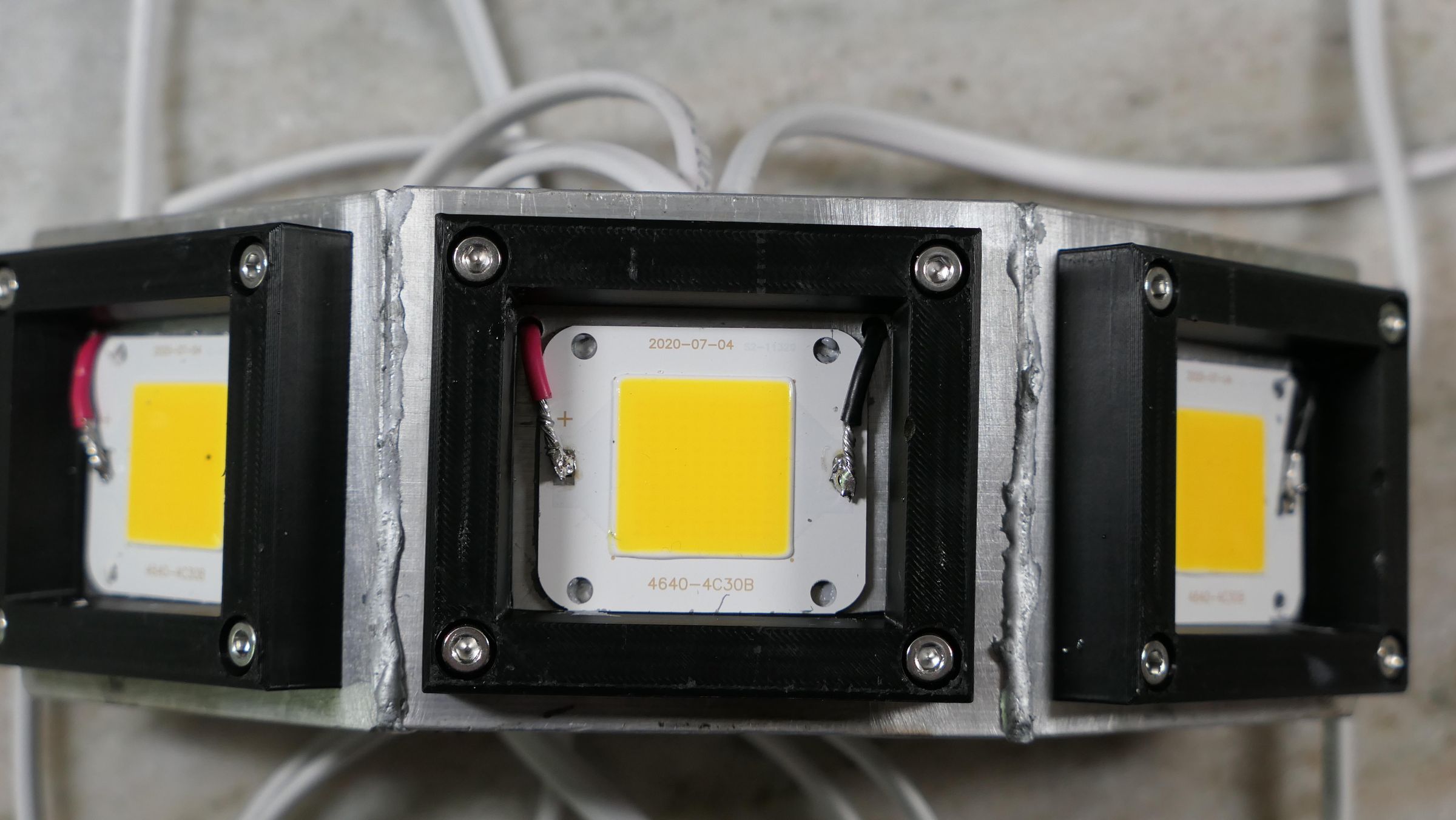
Without the pole attached, pass a ~7" length of 16ga marine wire to each COB location. Apply a thin, even layer of thermal paste to the back of each 50W LED chip, mount them, and solder the positive and negative wires directly to the chips.
Waterproof the Housing
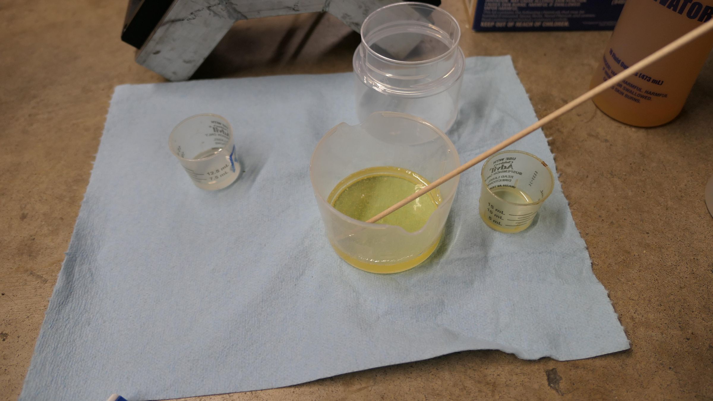
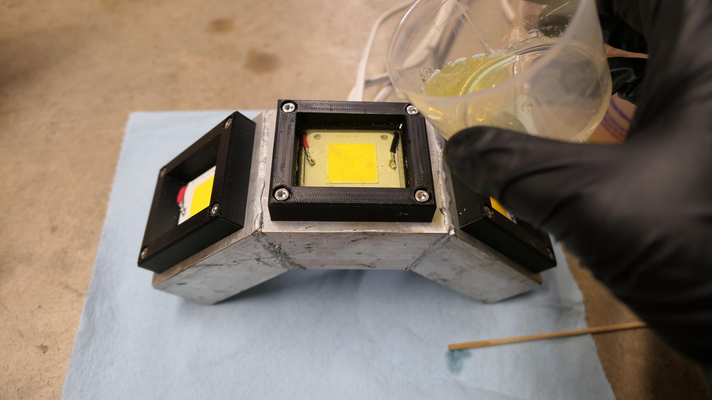
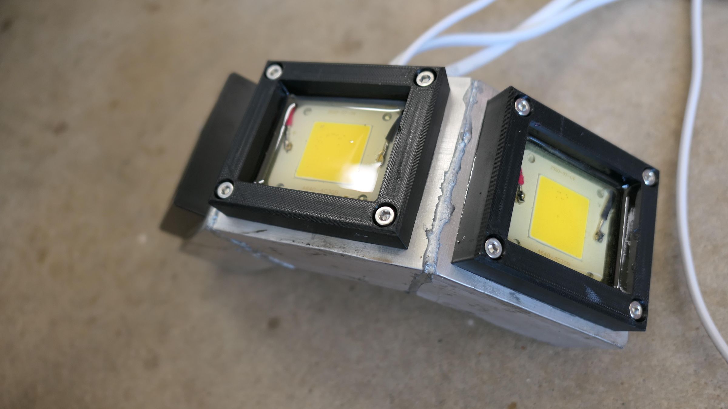
Mix your Varathane Super Glaze epoxy as directed. Set the light head flat and pour the clear epoxy over one mounted LED chip at a time until it completely covers the wires. Sweep a heat gun quickly over the surface to release trapped air bubbles, and allow each chamber to cure fully before angling the head to pour the next one.
Install Conduit Reducer Bushing & Switches
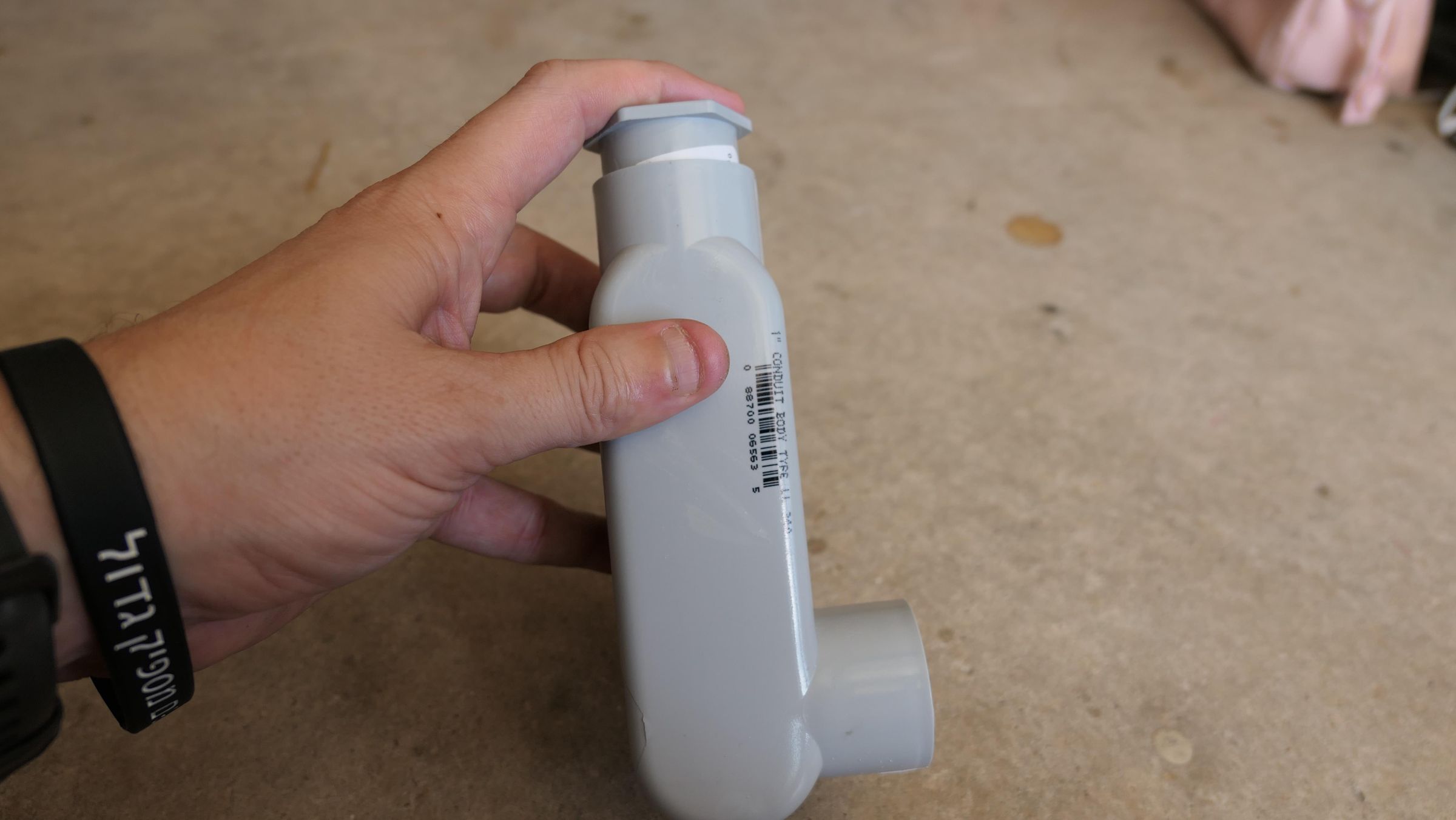
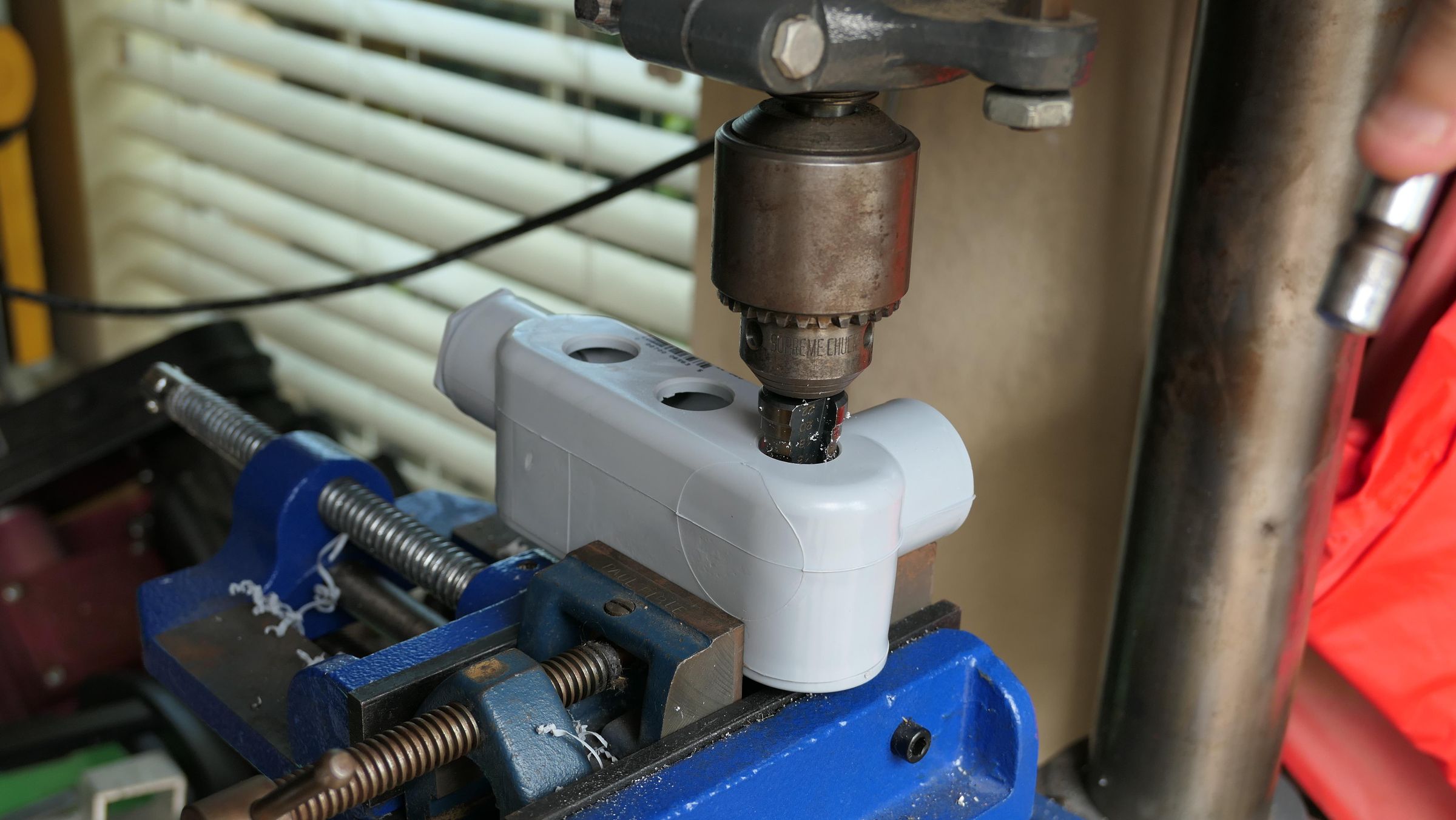
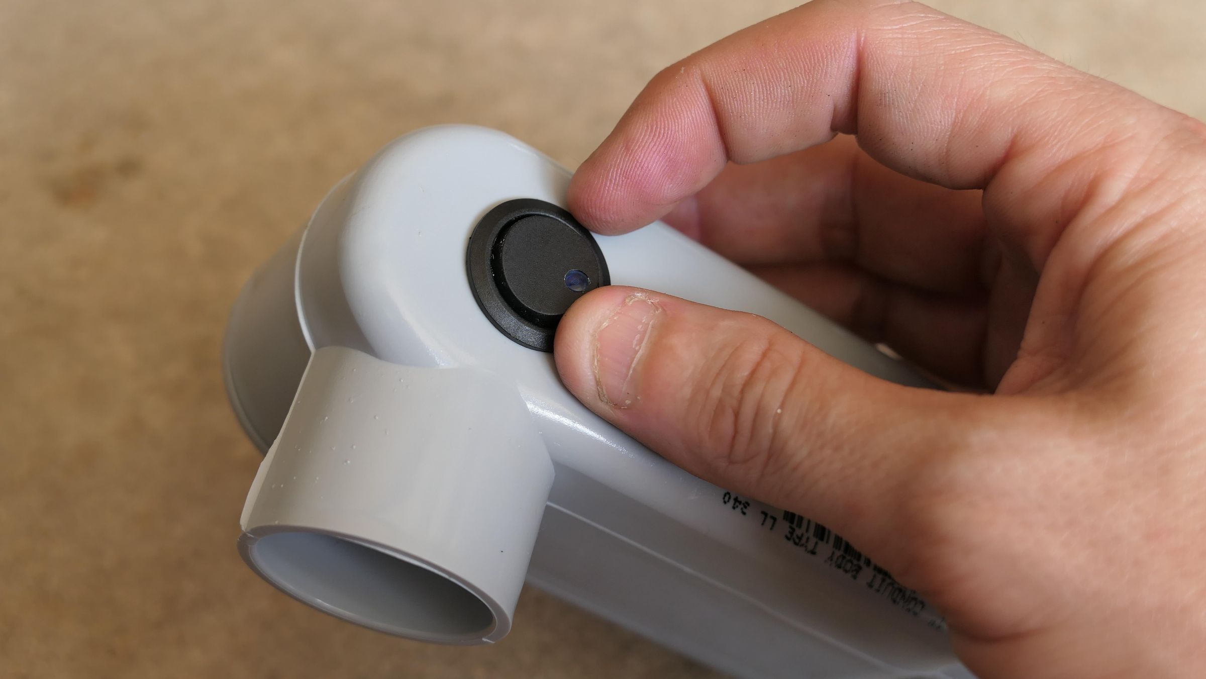
Press fit a 1" to 3/4" reducer bushing into the end of the LL conduit enclosure. Drill three 20mm holes in a neat line through the backside of your LL enclosure and press-fit your toggle switches (use super glue or marine epoxy if they feel loose).
Protect Wire Passthrough & Install Pole
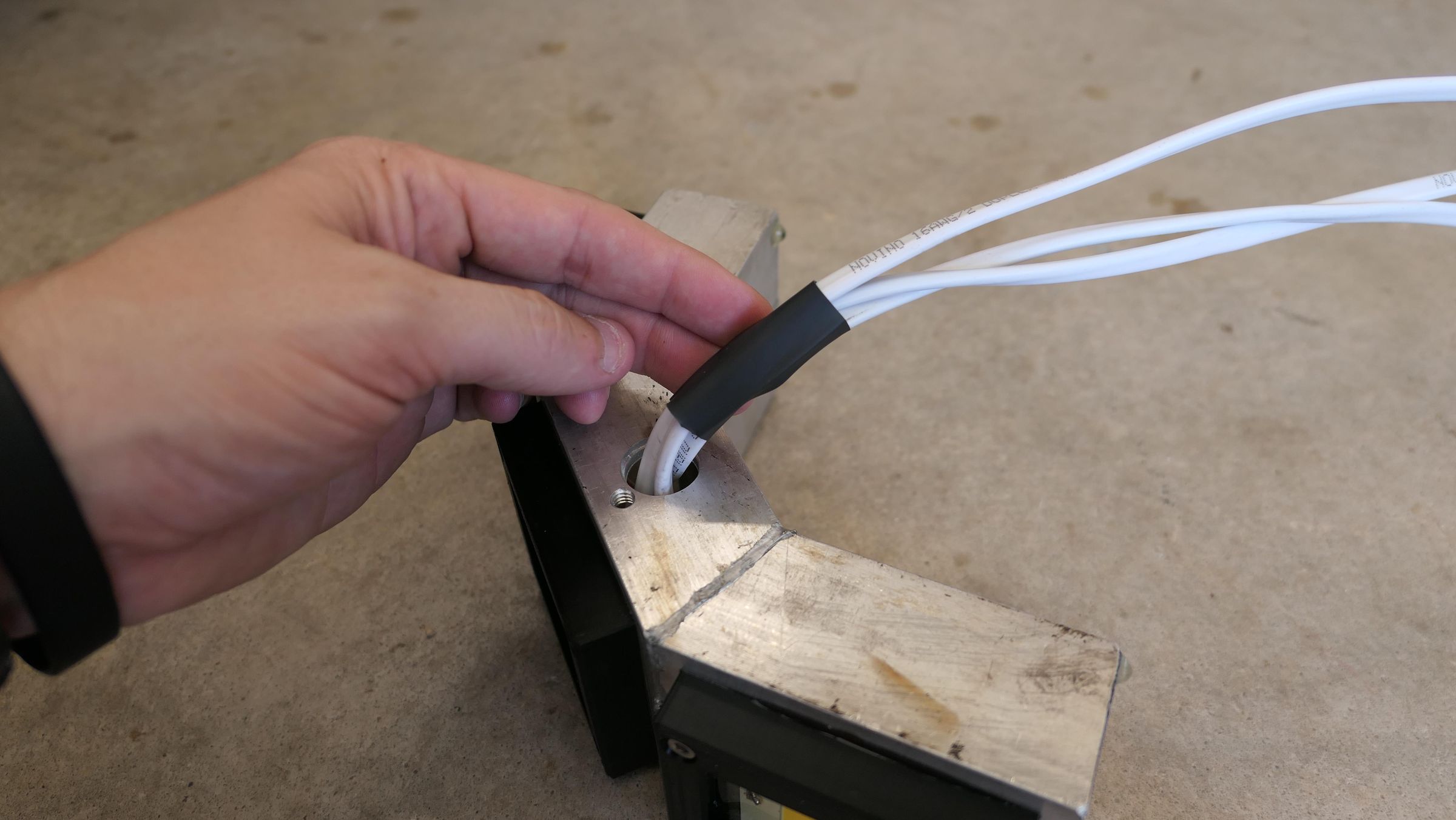
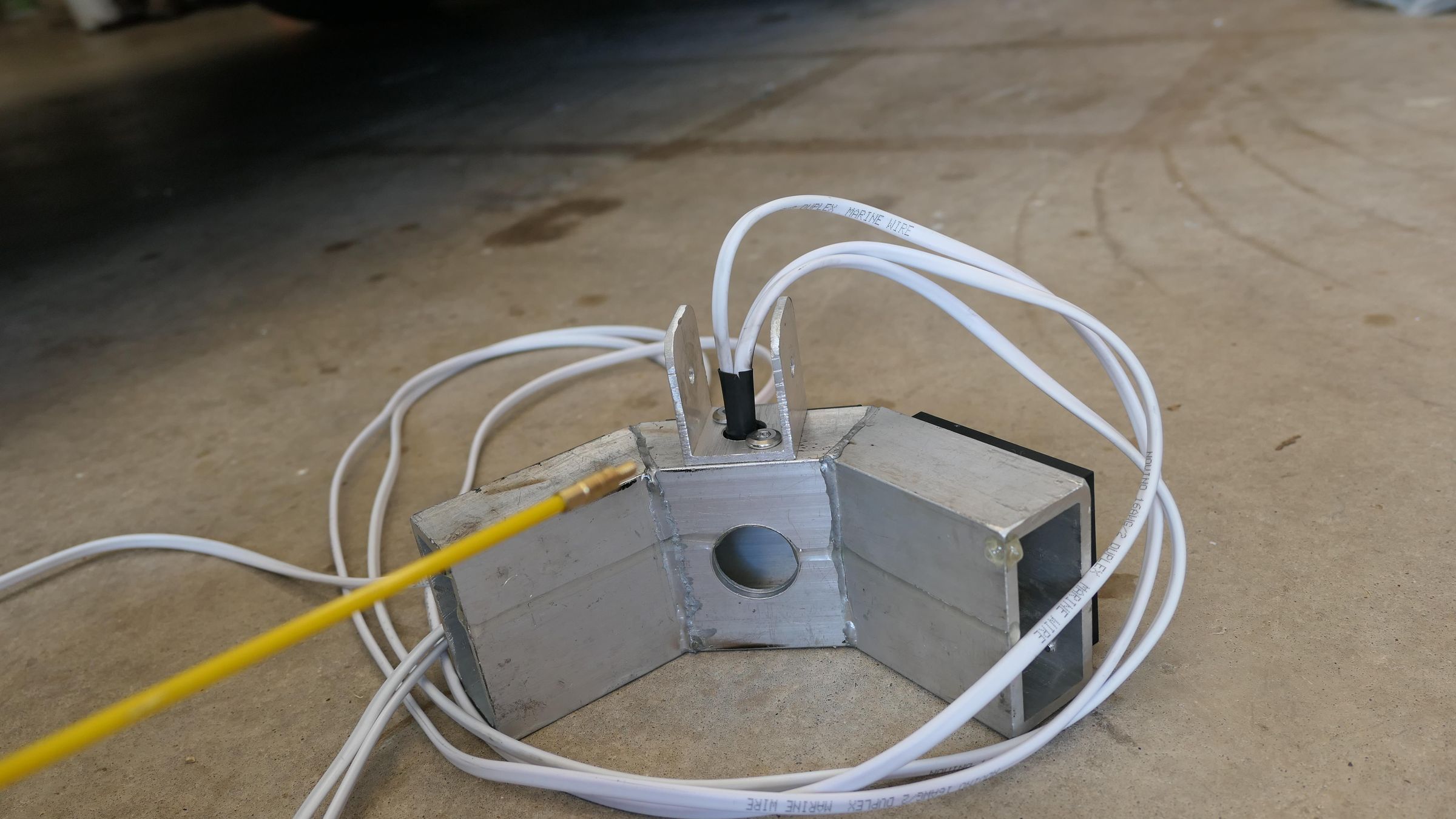
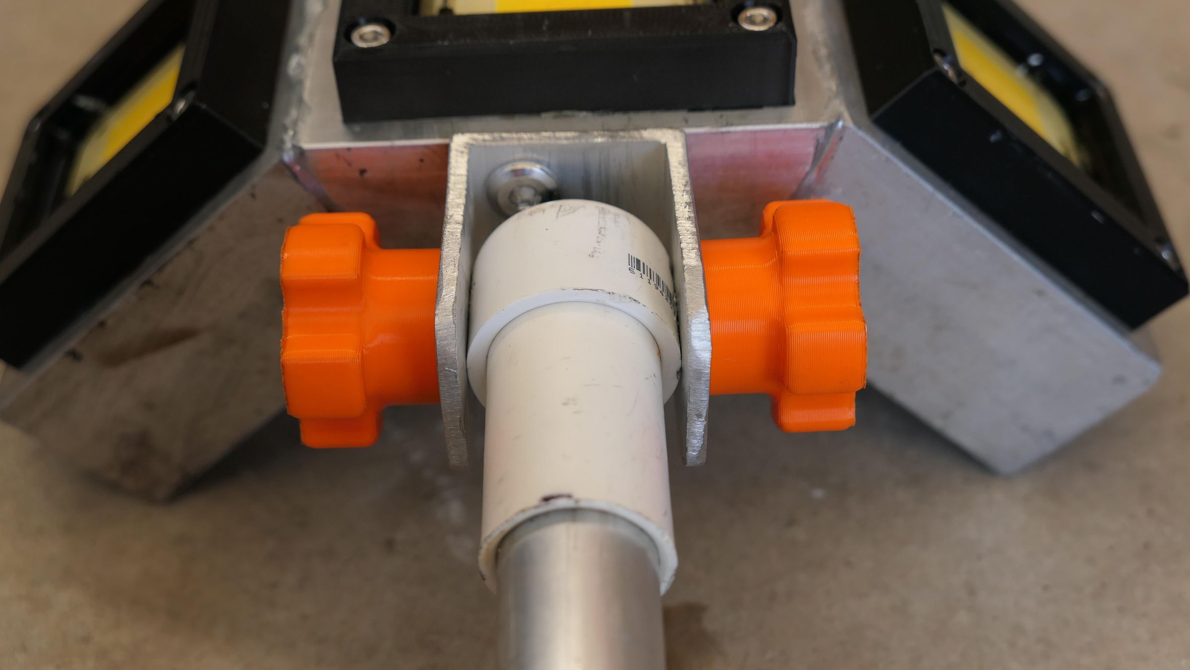
Install a 1/2" piece of heatshrink where the 16ga wires pass through the housing for extra protection. Using a fishtape, pull the three lengths of wire up through the aluminum pole, then fasten the pole to the hinge.
Wire the Rocker Indicator Lights
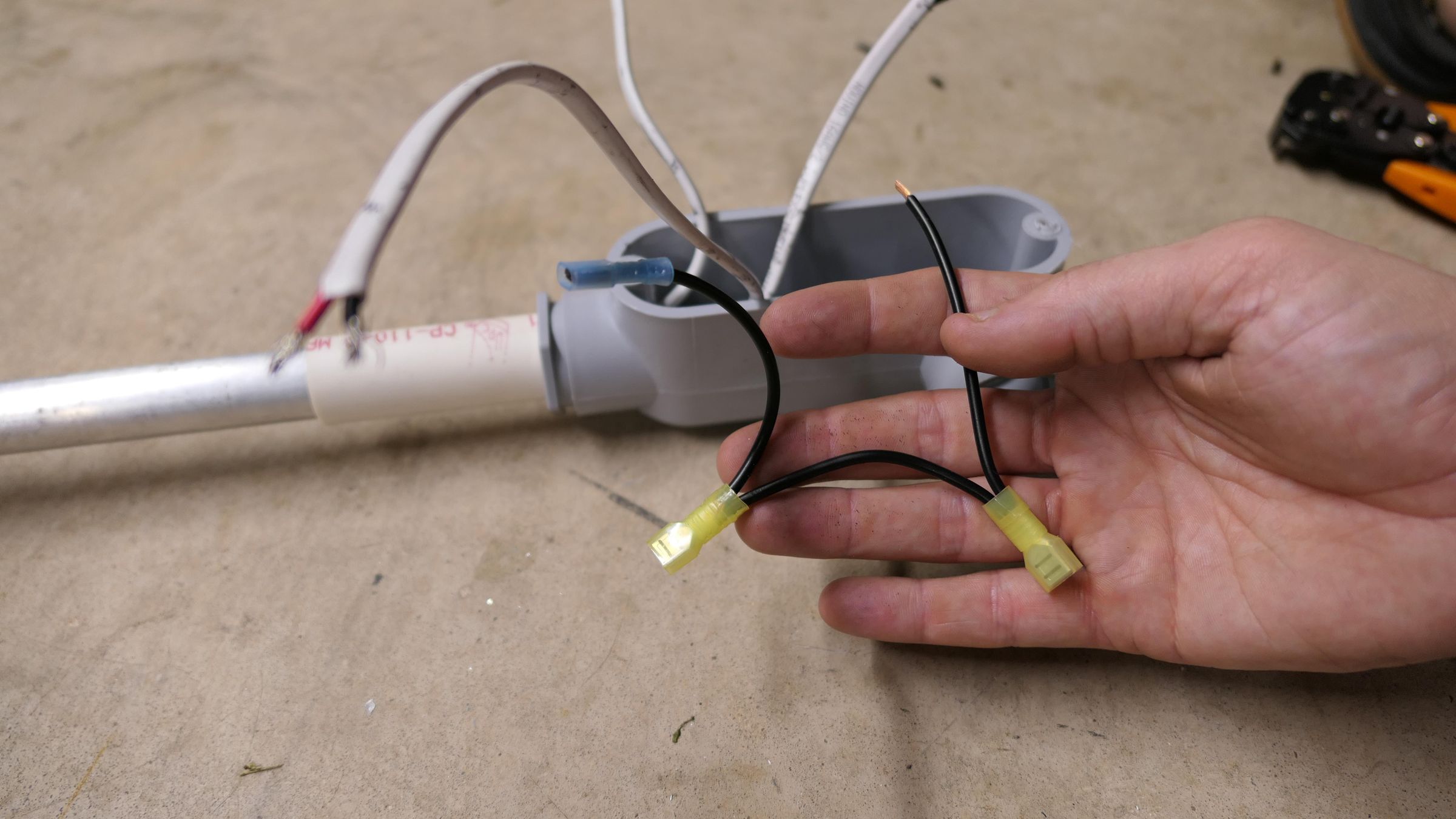
Inside the conduit body, chain the gold terminal using female spade terminals across all three switches and connect them to a 5-port Wago connector.
Connect Positive and Negative Loads
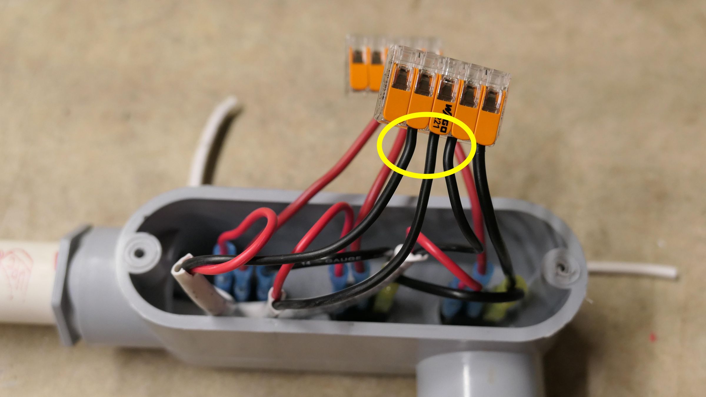
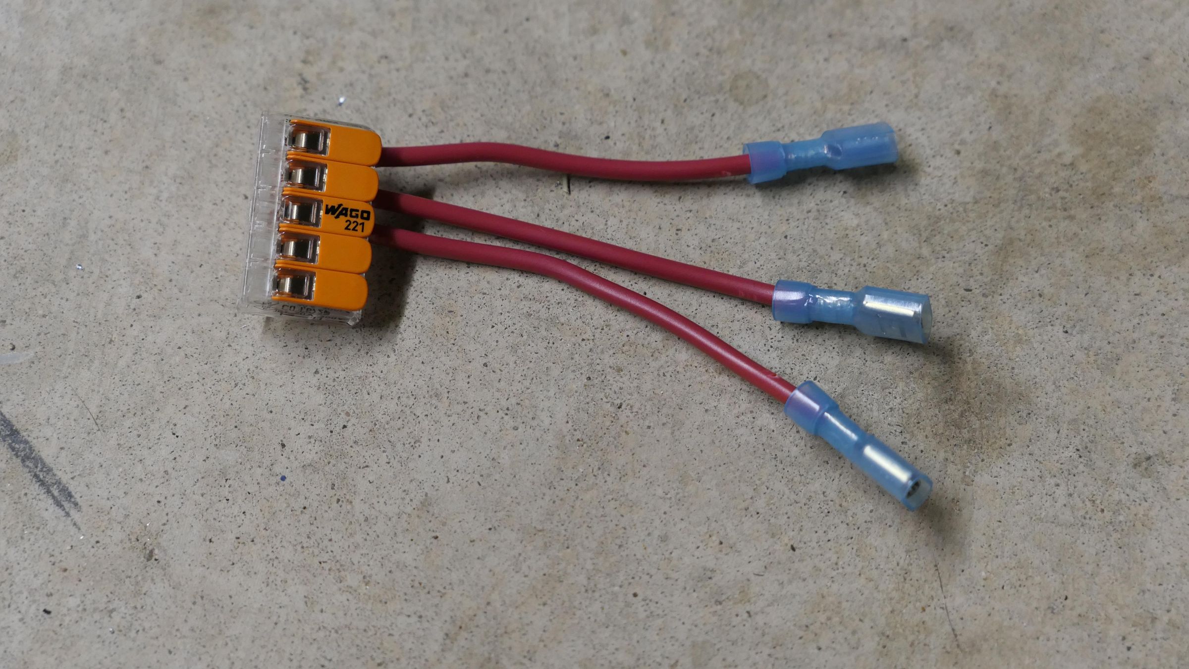
Using a 5-port Wago and 16ga wire, create a female spade jumper for each switch and connect it to the load terminal (middle terminal) of each rocker. Connect all the negative wires to the same 5-port Wago used in the previous step for the indicator LEDs.
Connect Battery Wiring
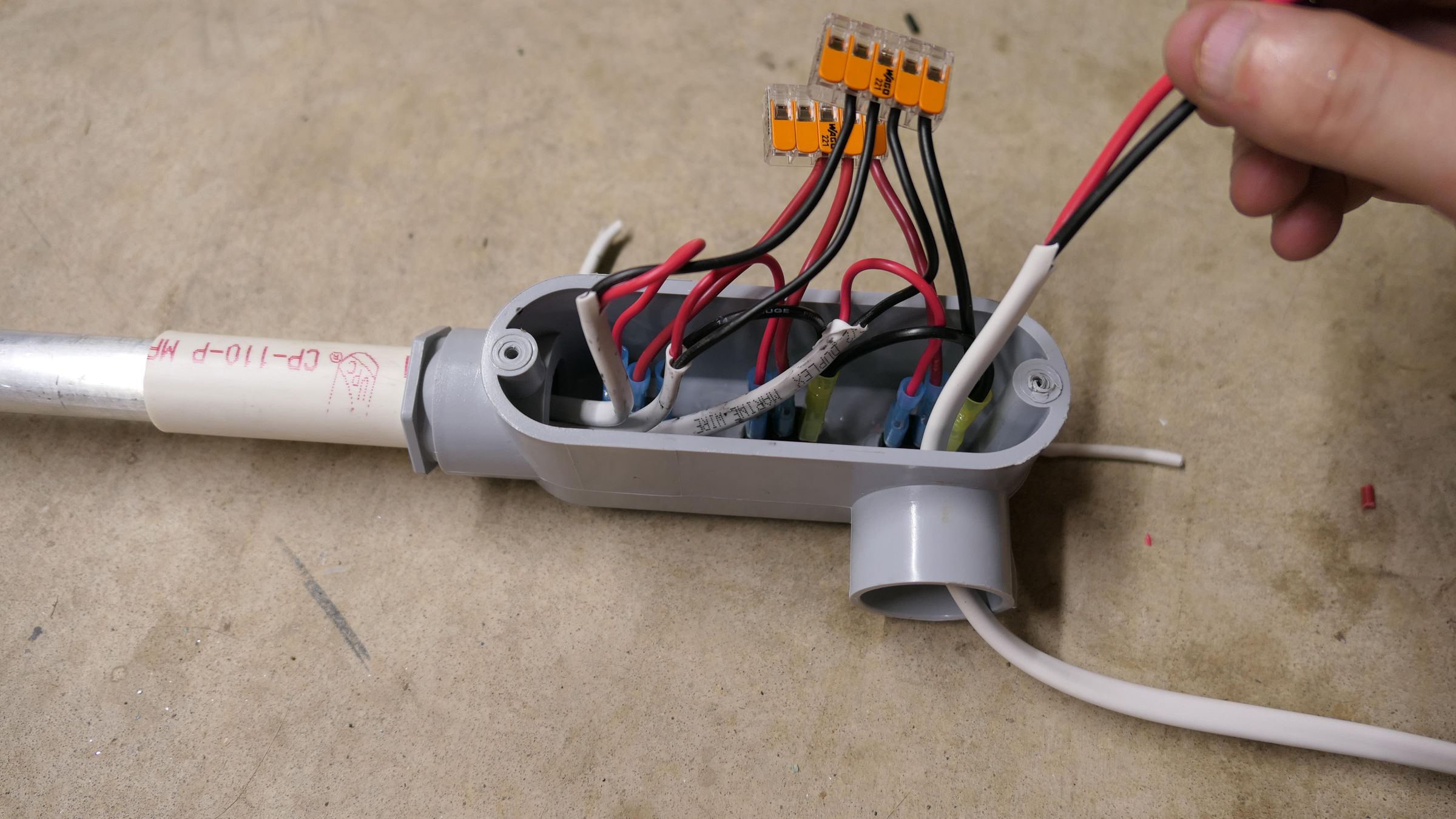
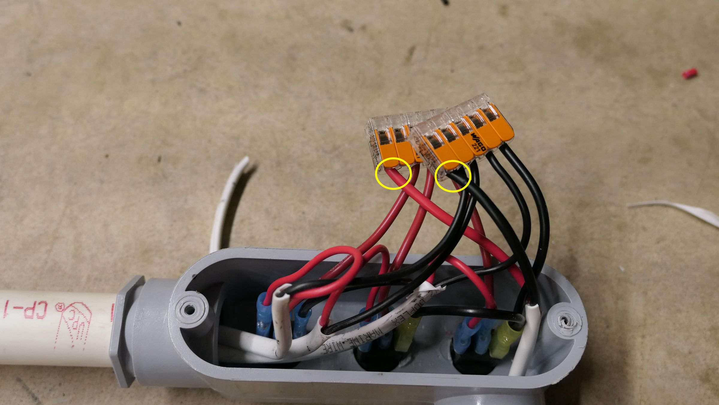
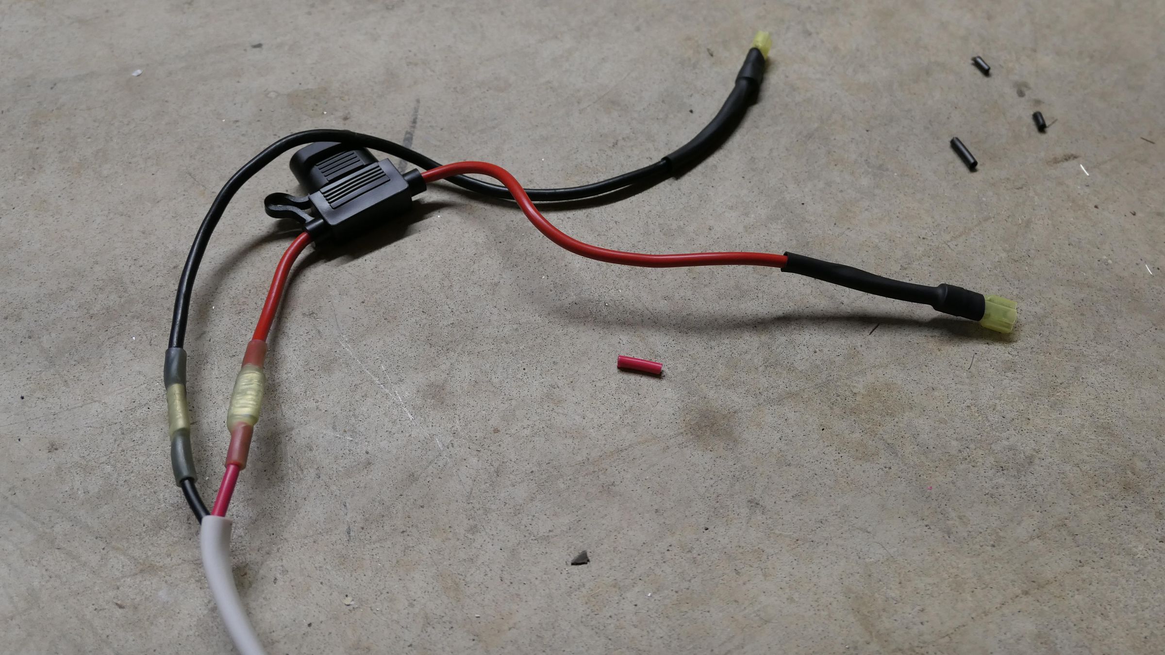
Using 12ga marine wire, run the main positive line to the positive Wago and the main negative line to the negative Wago. Using butt connectors, add a 20-amp fuse inline with the positive line. Terminate both the positive and negative lines with female spade connectors.
Hook Up the Battery
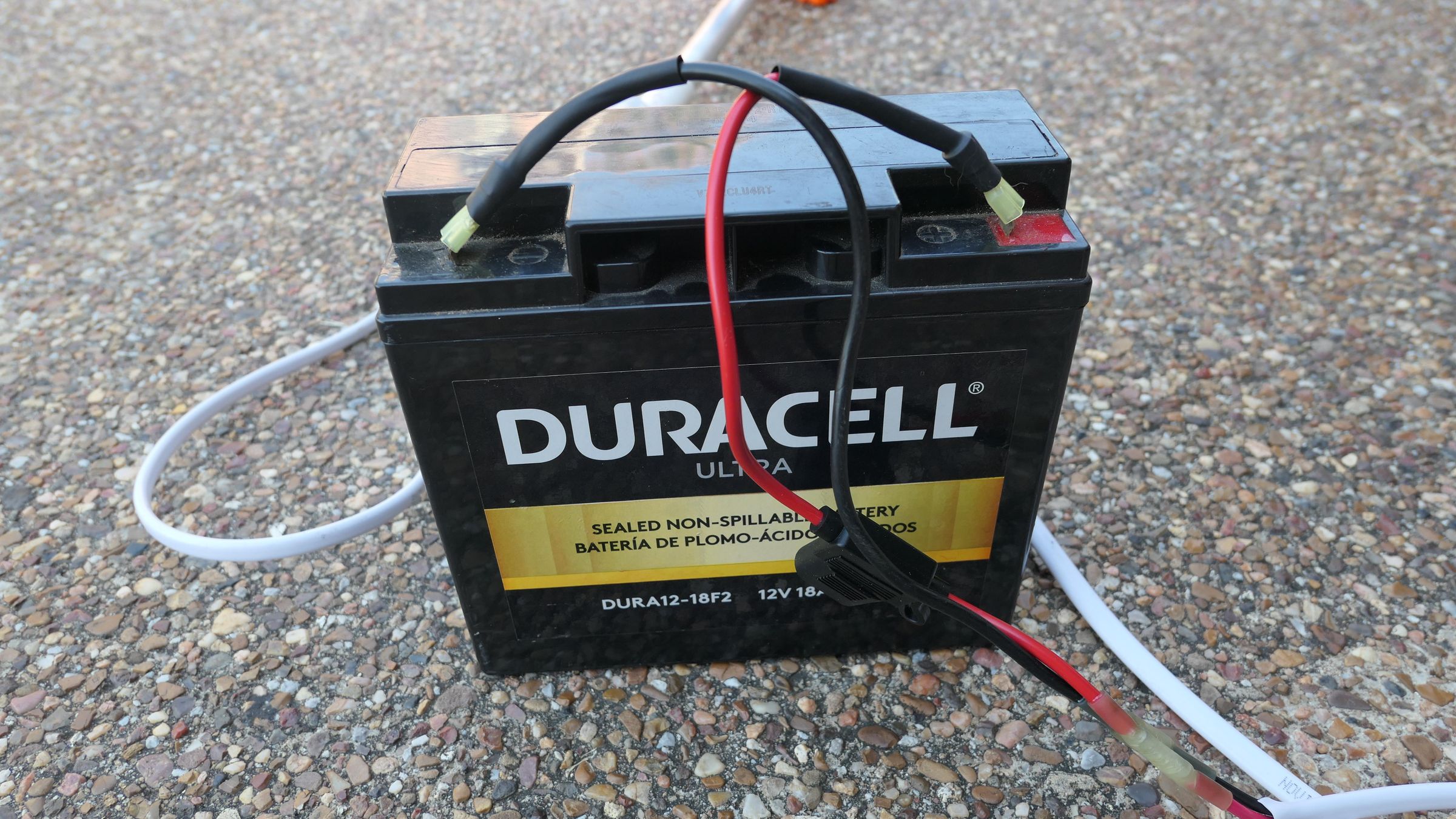
Connect the leads to your 12V 18Ah battery (which drops perfectly into a small backpack) and flip each toggle to ensure the individual circuits fire up cleanly before you head to the coast.
Conclusion
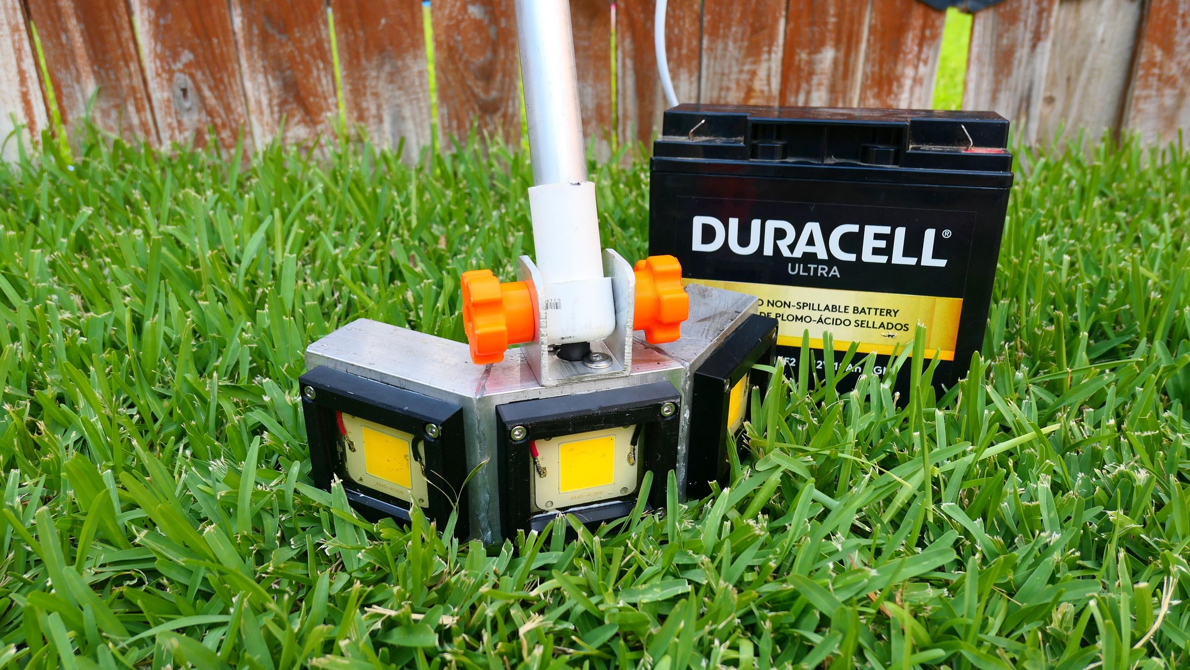
This aluminum design completely changes the game on the flats.
If you build your own version of this flounder light, be sure to share it below using the "I Made It!" button!
For more advanced design notes, 3D printing files, and future projects, check out the full build article over on Reckon I'll Outdoors and subscribe to my YouTube channel for other video builds.