Upcycled Phone Battery to Rechargeable Smart Emergency Nightlight
529 Views, 1 Favorites, 0 Comments
Upcycled Phone Battery to Rechargeable Smart Emergency Nightlight
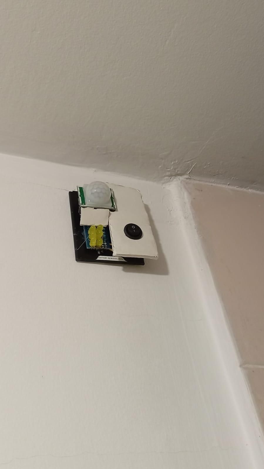
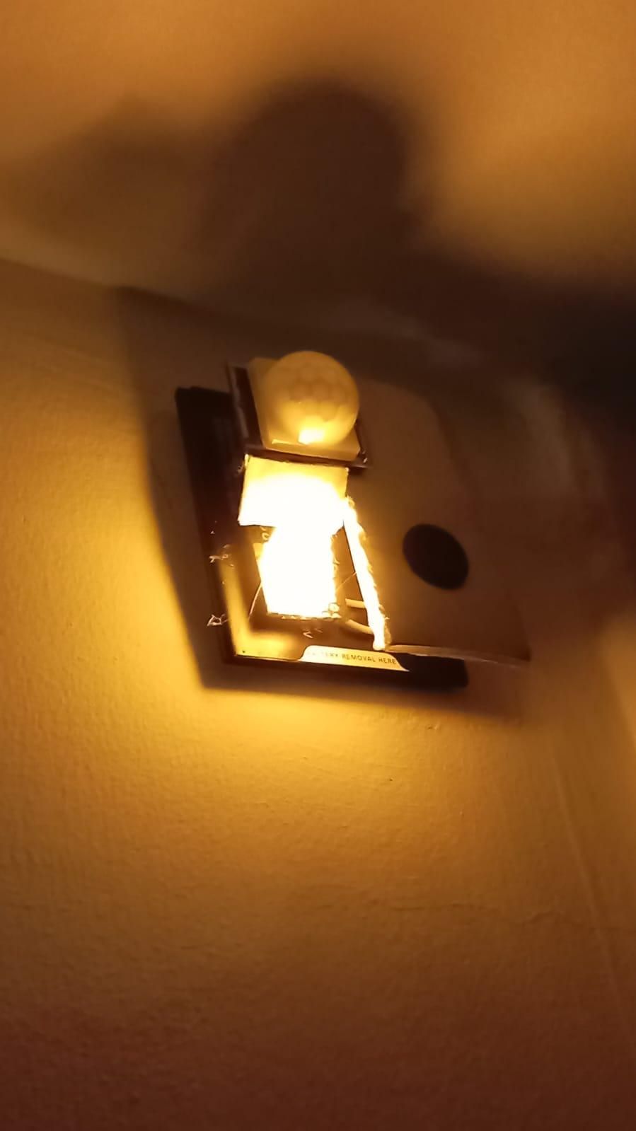
Upcycled Phone Battery to Rechargeable Smart Emergency Nightlight
Introduction
We’ve all been there: the power goes out, the house goes pitch black, and you're suddenly stubbing your toe on a coffee table trying to find a flashlight. Or perhaps you just have a dark hallway or closet that desperately needs some illumination, but you don't want to run permanent wiring.
Instead of buying mains powered motion triggered nightlights, or battery powered nightlights that only last a few nights before needing recharging, this project turns e-waste into a highly efficient, rechargeable, Smart Emergency Nightlight.
By upcycling a salvaged 3.7V lithium-ion battery (from an old cell phone, laptop, or even a disposable vape) and combining it with some cheap, off-the-shelf components, you can build a rechargeable nightlight that thinks for itself.
How It Works (The "Smart" Part)
To maximize battery life, this light doesn't just stay on all the time. It relies on a simple but powerful logic circuit combining two sensors:
- An LDR (Light Dependent Resistor): Senses the ambient room light.
- A PIR (Passive Infrared) Sensor: Senses body heat and motion.
The LEDs will ONLY trigger when it is both dark AND motion is detected. By limiting the battery draw in this way, the circuit is very efficient.
Expected Battery Life
Because the light only fires when absolutely necessary, the battery life is fantastic. Using a standard upcycled cell phone battery (around 2600mAh capacity), this light can sit in "active standby" for about 2 months on a single charge before needing to be plugged in for recharging!
If you want to use this strictly as a blackout/emergency light, I've also included a master power switch. Keep the switch flipped off, and the battery will hold its charge for months on end, ready to flip on the second you lose power.
Perfect Locations for this Build:
- Bathrooms & Hallways: For midnight trips without blinding yourself with the main lights.
- Closets & Cabinets: Automatic lighting the second you open the door.
- Staircases: Essential safety lighting during power outages.
- Emergency Kits: A reliable, rechargeable light source that's ready when the grid goes down.
⚠️ A Quick Note on Safety
This project involves salvaging and reusing Lithium-Ion (Li-ion) batteries. Li-ion batteries can be dangerous if punctured, short-circuited, or charged improperly. Always inspect your upcycled batteries for swelling or damage before using them, and ensure your charging module is wired correctly!
Inspiration & Credit
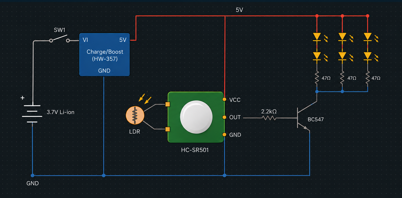
The core circuit logic for this project was inspired by a design featured on the excellent bigclivedotcom YouTube channel. If you enjoy reverse-engineering circuits or learning how cheap electronics tick, definitely go check out his videos! A diagram of the circuit, created with the help of Gemini Pro, is given in the reference photos.
If you have basic soldering skills and an afternoon to spare, let's dive in and build one!
Supplies
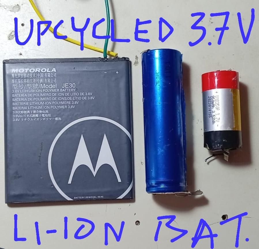
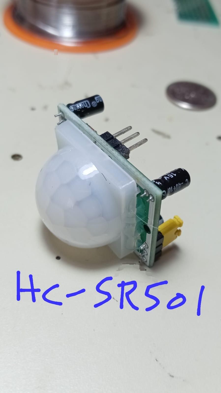
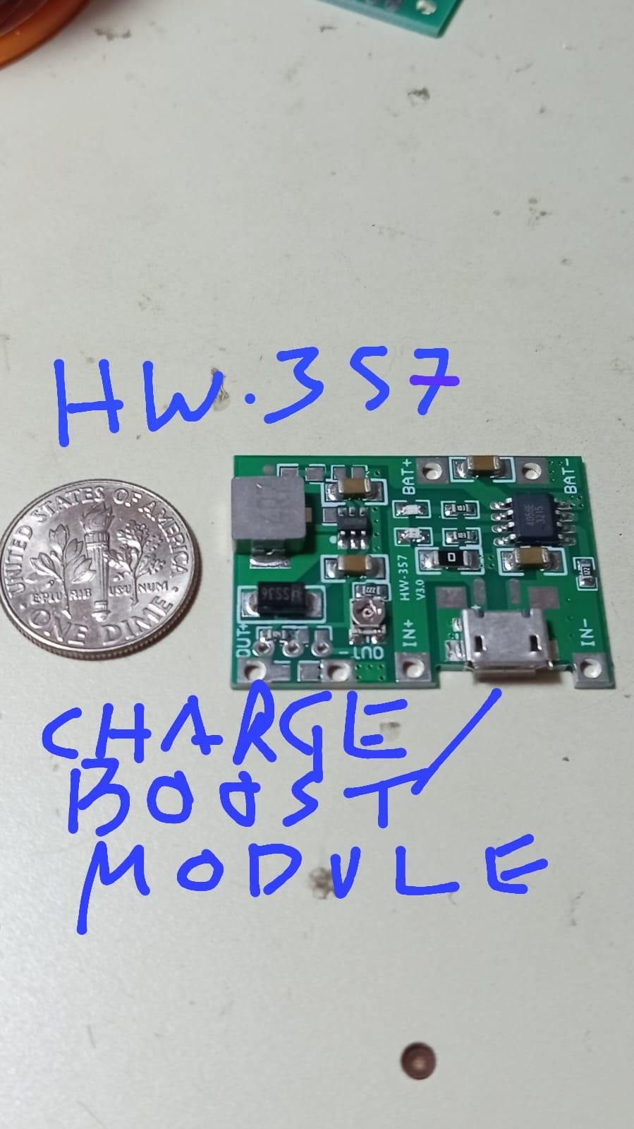
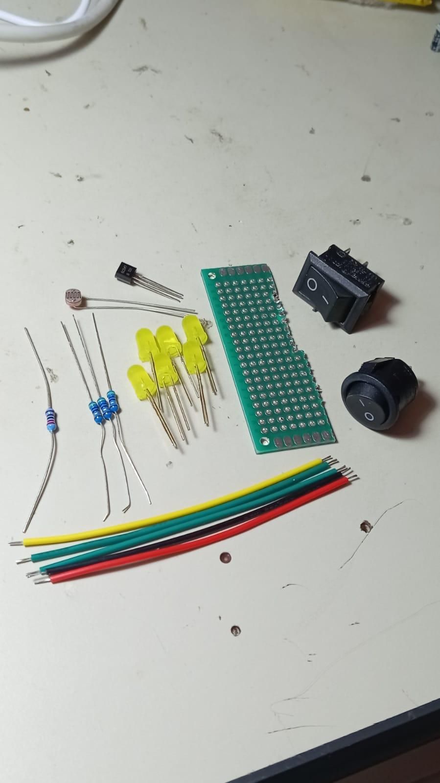
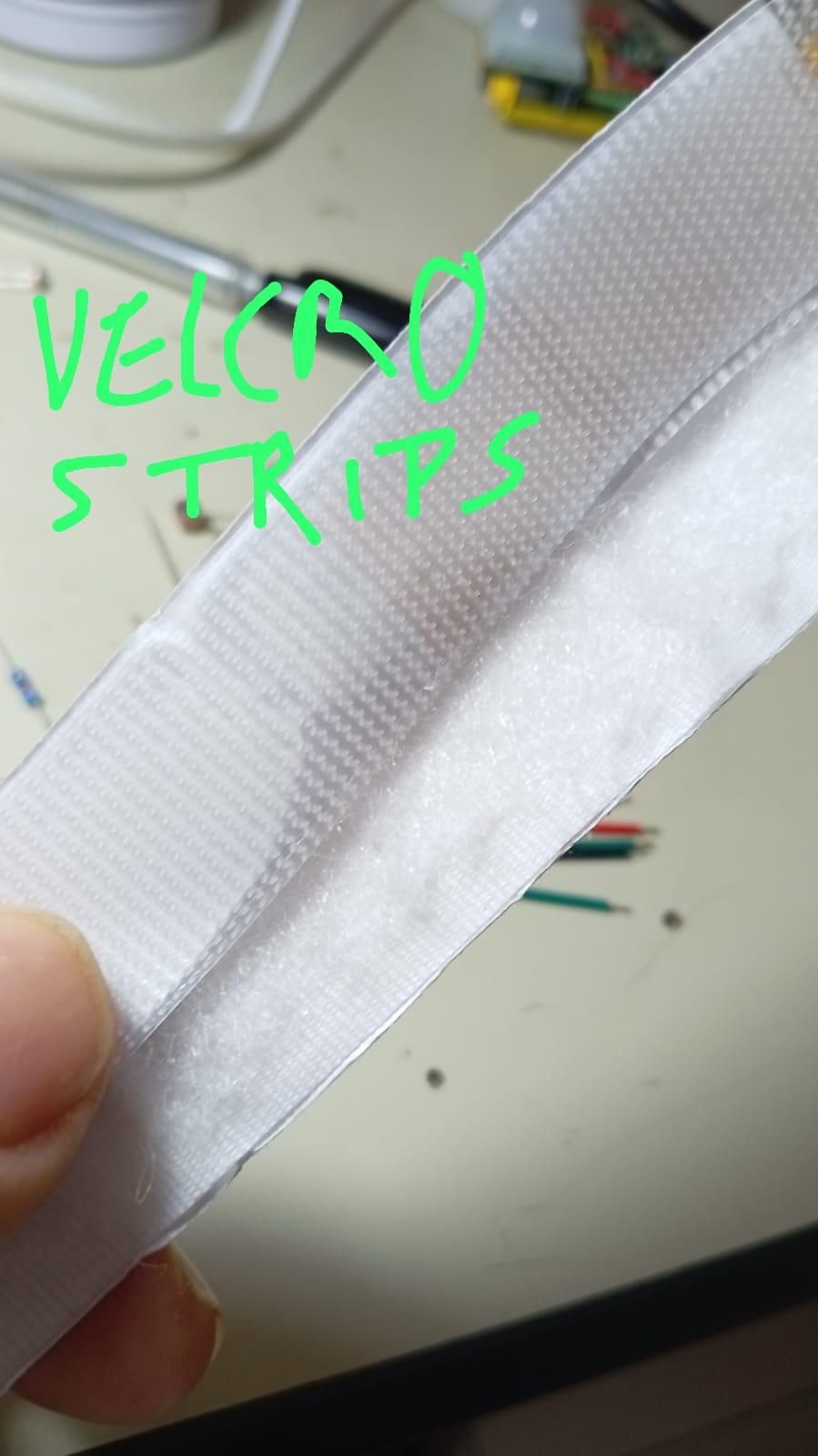
To build this smart nightlight, you'll need a mix of salvaged parts and a few inexpensive standard electronic components.
Electronic Components
- 1x Upcycled 3.7V Lithium-Ion Battery (Salvaged from an old cell phone, laptop, or rechargeable vape).
- 1x HW-357 or J5019 Charge/Boost Module (This safely charges the battery via USB and boosts the voltage to power the LEDs. A Wemos D1 Mini Battery Shield will also work. Other charge/boost boards with overcharge protection and 5V OUT may also work, but avoid boards with the "auto-off" feature.)
- 1x HC-SR501 PIR Motion Sensor
- 1x LDR (Light Dependent Resistor / Photoresistor)
- 1x NPN Transistor (e.g., BC547 or 2N2222)
- 6x Standard LEDs (5mm yellow or red LEDs are highly recommended. They have a lower voltage requirement (~2V), meaning two of them in series works perfectly on our 5V supply. White, blue, or green LEDs require ~3.2V each; two in series need over 6V and simply will not light up on this 5V circuit. Using those colors requires wiring them individually in parallel and calculating new resistor values.)
- 1x 2.2kΩ Resistor (For the transistor base).
- 3x 47Ω Resistors (Current-limiting resistors for the LED branches).
- 1x SPST Power Switch (A simple rocker or toggle switch for manual on/off).
- 1x Single Row Female Header (At least 3 pins long, for socketing the PIR sensor).
Hardware & Miscellaneous
- Perfboard / Prototyping Board (A piece at least 6 holes wide x 18 holes long).
- Scrap Wire / Jumper Wires
- Scrap Cardboard/Foam board/Plastic (Optional, to hide the wiring or mount components).
- Adhesive Velcro Strips (Highly recommended for easy positioning on walls, inside closets, or under cabinets; and easy removal for charging).
- Heat shrink tubes (Optional, to help avoid contact between the LDR legs and metal pins on the HC-SR501).
Tools Required
- Soldering Iron, Solder, & Flux (For solder I used 2% flux 0.6 diameter 63/37).
- Wire Cutters & Strippers
- Digital Multimeter
- Hot Glue Gun
- Safety goggles (To use when soldering and when inspecting salvaged batteries).
- Solder fume extractor (Or some form of good ventilation to prevent excessive inhalation of solder fumes).
- Alligator clip wires (Optional, helpful for test charging li-ion batteries before soldering).
- Sandpaper (150 or 180 grit) (Optional, to facilitate soldering wires to battery terminals).
- Hobby Knife or Box Cutter (Optional, for lightly scoring the battery terminals to facilitate soldering).
Find a 3.7V Lithium Ion Polymer Battery Suitable for Upcycling
Search your home or local battery/e-waste bin for a discarded 3.7V Li-Ion battery. These can be the flat kind found in cell phones or the cylindrical kind found in laptop battery packs ("18650" batteries). Vape batteries will also work but have lower capacity (mAh) and so won't last as long before a recharge is needed.
⚠️ SAFETY FIRST: Use safety goggles when inspecting batteries of uncertain provenance. Make sure the battery is not swollen, leaking, punctured, dented, bent out of shape, or smelling funny.
1. Initial Voltage Test If the battery passes the visual inspection, use a multimeter to determine the charge.
- If the + and - terminals are not clearly labeled, clearly label the + terminal yourself with a marker to avoid accidental short circuiting when wiring things up.
- If the charge is at least 2.8V, then the battery is probably salvageable. (Otherwise, it has likely degraded too far—return it to the e-waste bin.)
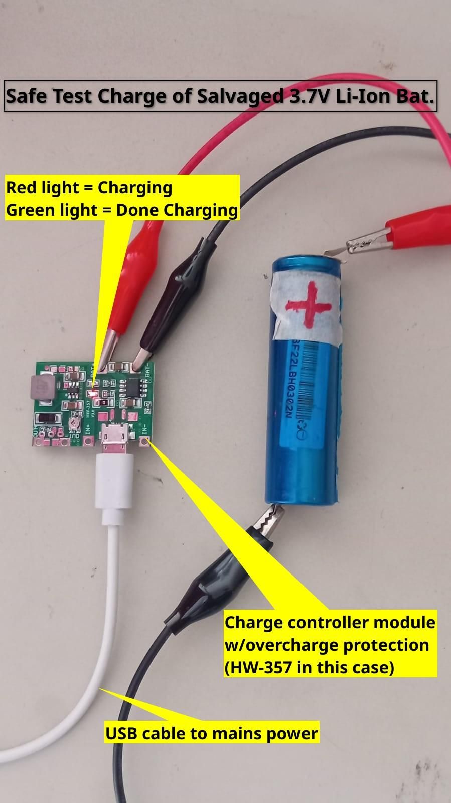
2. Test Charging Charge it up safely using a charge controller module with overcharge protection (the HW-537 or J5019 charge/boost module mentioned in the supplies list could serve this purpose, or a TP4056).
- Keep an eye on the charging process every 15-30 minutes. Abort immediately if the battery starts to get hot.
- When the charge controller module indicates a full charge (e.g., a green light on the HW-537/J5019 or a blue light on the TP4056), disconnect the battery and test its voltage with your multimeter. It should read roughly 4.0V to 4.2V.
3. The Holding Charge Test If the battery reaches a full charge, leave it sitting for a day or two and then take another voltage reading. If it still holds the same 4.0V to 4.2V charge, then the battery may be considered suitable for upcycling. Otherwise, return it to the e-waste bin.
Note: Alternatively, you can just buy a new 3.7V Li-Ion battery, e.g., on AliExpress. But upcycling is cheaper, greener, and far more impressive to your friends, family, co-workers, boss, and pets.
Configuring the HC-SR501 PIR Motion Sensor
Before we start soldering the main circuit together, we need to configure the "brain" of our operation: the HC-SR501 PIR motion sensor. This little green board has a few physical settings that we need to adjust to make our smart nightlight behave exactly how we want.
Setting the Trigger Mode (L vs. H)
On the edge of the board, you will find three pins (or pads) labeled with an L and an H. This sets the "Trigger Mode" of the sensor.
- L (Single Trigger Mode): In this mode, the sensor detects motion, turns the light on, and starts a countdown timer. If you keep moving in the room, it ignores you until the timer runs out, turns the light off, and resets. (This leads to annoying flickering if you are in the room for a while).
- H (Repeat Trigger Mode): In this mode, every time the sensor detects motion, it resets the countdown timer back to zero. The light will stay on continuously as long as you are moving nearby.
For a nightlight, you absolutely want to use the "H" (Repeat Trigger) setting.
A Note on Different Modules: Depending on where you bought your sensor, yours might look a bit different:
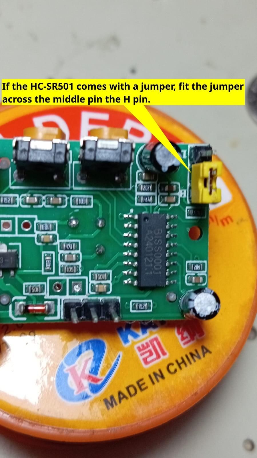
- Jumper Block: Older or slightly more expensive modules have three pins and a little yellow (or black) jumper block. Simply pull the block off and slide it over the middle pin and the "H" pin. (See the reference photo with the yellow jumper).
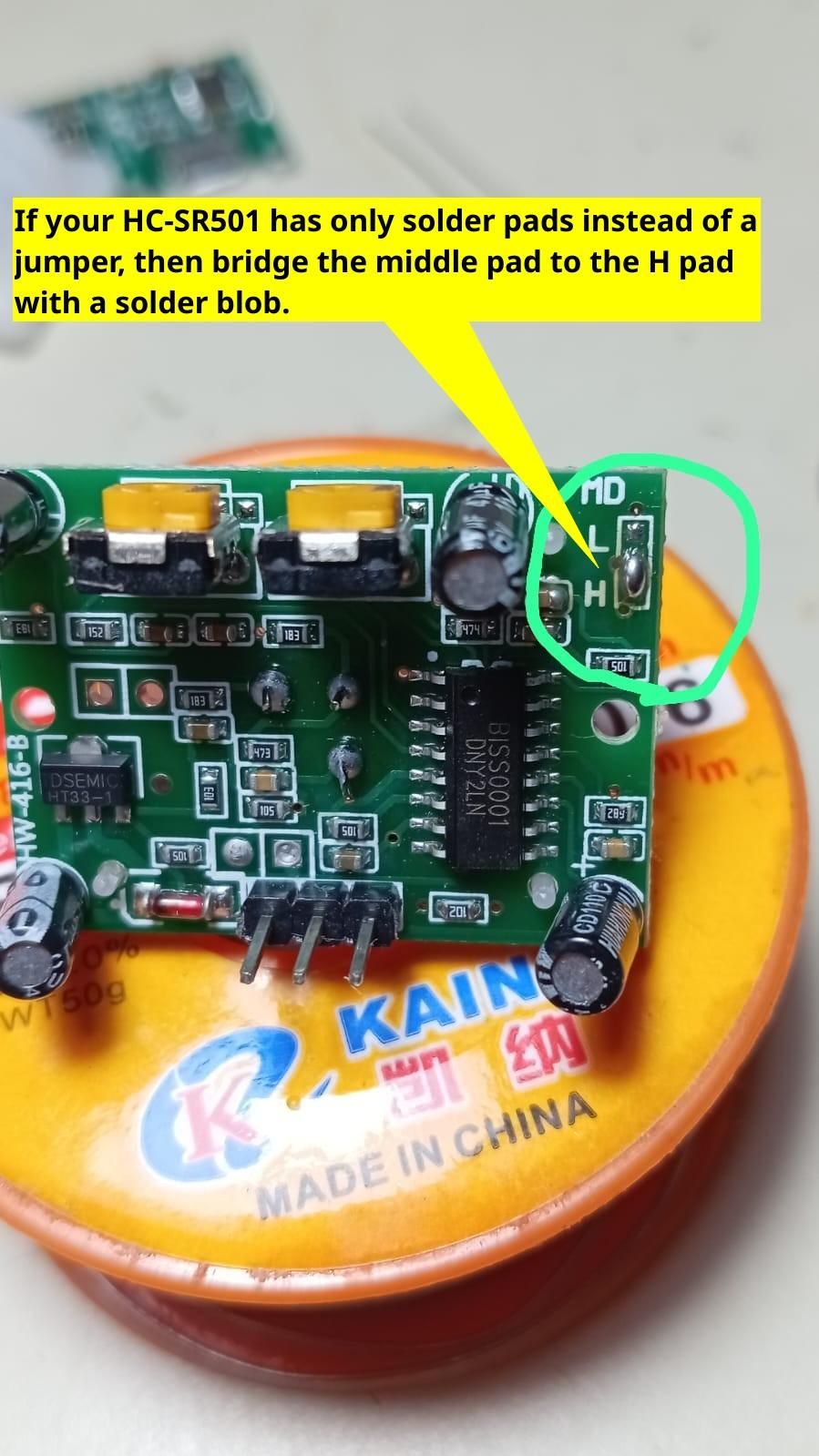
- Solder Pads: Many modern modules cut costs by replacing the pins with three bare copper pads. To select the mode, use your soldering iron to create a small "solder bridge" (a blob of solder) connecting the middle pad to the "H" pad. (See the reference photo showing the bridged solder pads).
Tuning the Adjustment Knobs
Look at the side of the module opposite the pins, and you will see two orange potentiometers (knobs) with crosshairs in them. These control how the sensor reacts. If you hold the module with the white dome pointing up and these orange knobs facing you:
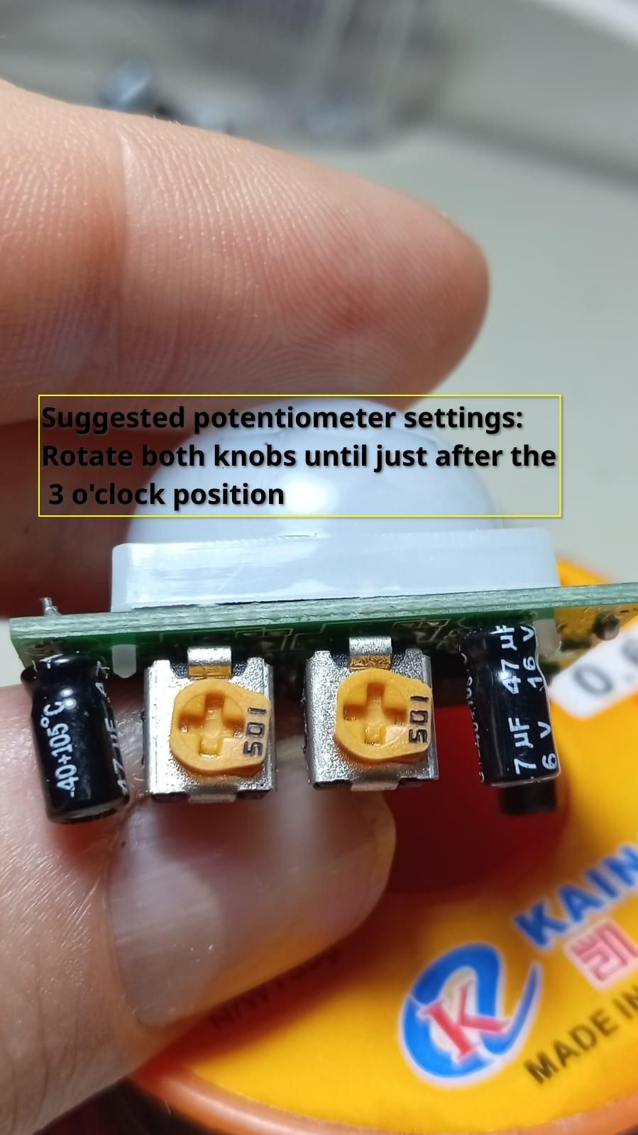
1. Sensitivity (Left Knob) This adjusts how far away the sensor can detect motion (roughly 3 meters up to 7 meters). The farther clockwise, the more sensitive. In my experience, turning the knob much past the 3 o'clock position results in hypersensitivity, such that the light remains on regardless of whether there is actually any meaningful motion taking place.
- Recommendation: Turn this to the 3 o'clock position for starters. Adjust slightly lower/higher if you feel like the detector is too sensitive/not sensitive enough.
2. Time Delay (Right Knob) This adjusts how long the light stays on after you stop moving. In my experience, turning this much past the 3 o'clock position results in the light staying on for way too long. On the other hand, turning this much lower than the 3 o'clock position results in the light turning off too quickly.
- Recommendation: Turn this to the 3 o'clock position for starters. Adjust slightly lower/higher if you feel like the light is staying on too long/not long enough.
The recommended knob settings are also shown in the attached reference photo.
(Tip: You can use a small screwdriver to gently turn these orange knobs. Don't force them past their stopping points.)
Add in the Light Sensor
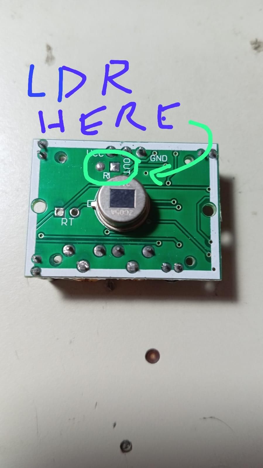
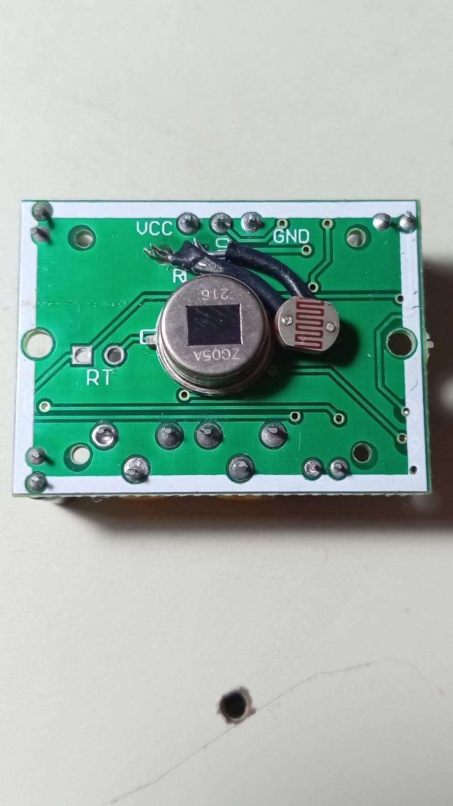
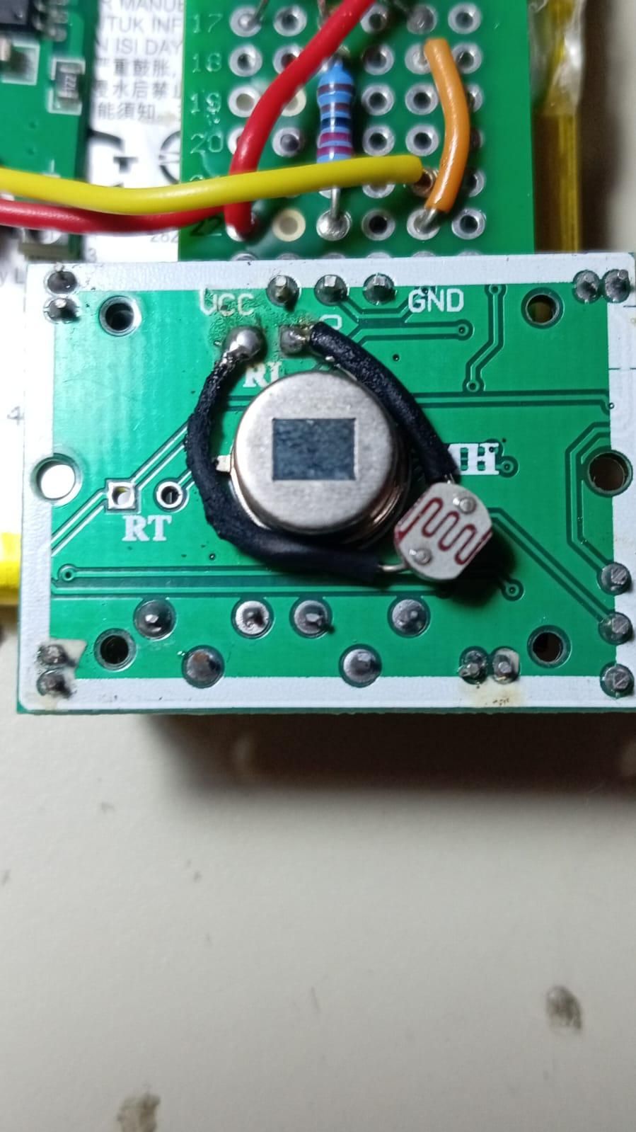
To make sure the nightlight turns on only when it is needed (i.e., when it is dark), solder the LDR to the designated pads under the white plastic dome on the HC-SR501, as shown in the reference photos.
LDRs have no polarity, so it does not matter which leg goes to which pad.
I have tried two different approaches, one where the LDR legs "hug" the central PIR sensor, and one where both legs wrap around one side of it (see reference photos). In either case, the LDR legs must be carefully measured and cut so as to ensure that the LDR fits cleanly under the white plastic dome, and so that the LDR legs avoid contact with any metal bits on the HC-SR501 board. For additional precaution, put rubber heat shrink tubes around the LDR legs to guarantee zero direct contact between the LDR legs and any metal bits on the PIR board.
If you find a better way, let me know in the comments.
(Tip: Before putting the plastic white dome back on, give the rectangular PIR sensor lens a gentle polish with some cotton. Smears on the lens like those seen in the reference photos can adversely affect motion detection.)
Assembling the Main Logic & LED Circuit
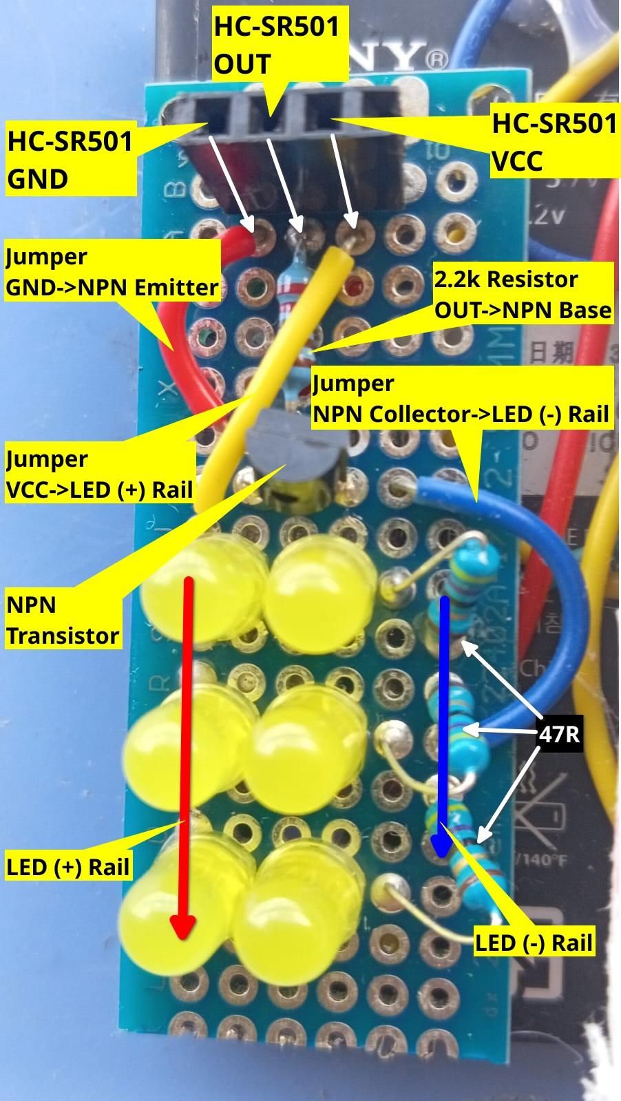
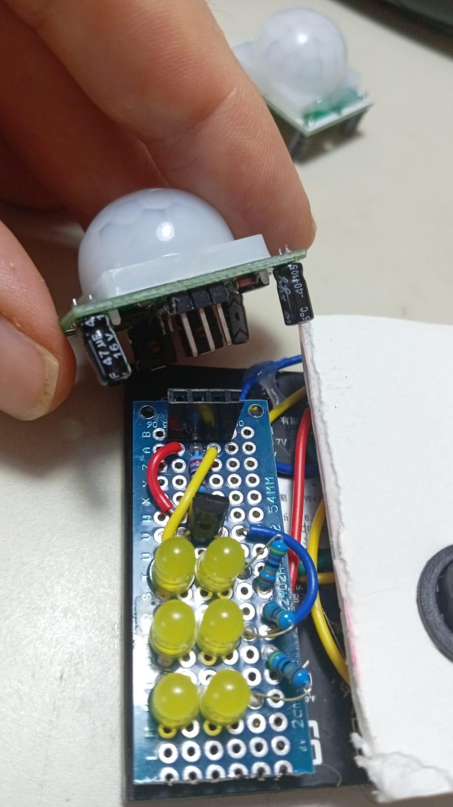
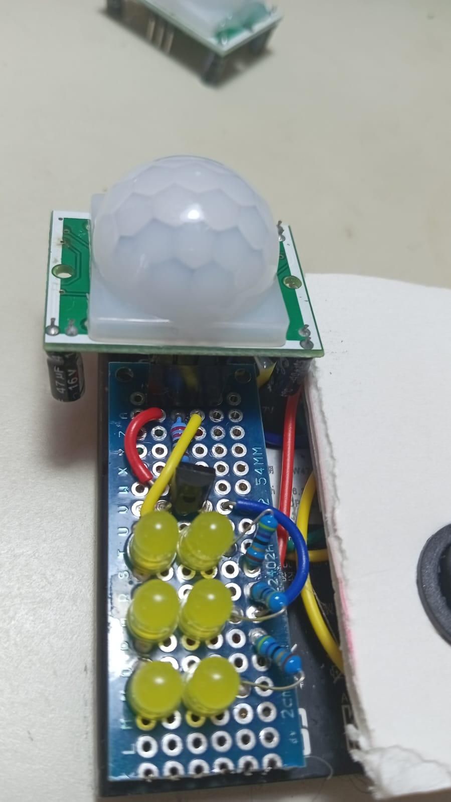
Step 4: Assembling the Main Logic & LED Circuit
Now that the PIR motion and LDR light sensor unit is prepped and configured, we can assemble the main circuit on our perfboard (a 6 x 18 hole piece works perfectly). We will wire up the "logic" (the sensor unit and transistor) and the "load" (the LEDs).
1. Mount the PIR Header Instead of soldering the HC-SR501 directly to the perfboard, solder a 3-pin single-row female header near the top of the perfboard.
- This creates a removable socket for the PIR sensor, making it easy to swap out later if needed.
- The three pins correspond to VCC (5V), OUT (Signal), and GND (Ground). These pins are usually labeled beneath the white plastic dome, making it easy to confirm which pin is which.
2. Wire the Transistor Logic The BC547 transistor acts as an electronic switch. When the PIR sensor detects motion, it sends a tiny signal to the transistor, which then clicks "on" to allow power to flow through the LEDs.
- Solder the 2.2kΩ resistor between the center pin (OUT) of the female header and the Base (middle leg) of the transistor.
- Solder a jumper wire from the GND pin of the female header to the Emitter leg of the transistor.
3. Build the LED Array We are using 6 LEDs, wired in 3 parallel rows (each row containing 2 LEDs in series).
- The Positive Rail: Solder the positive (longer) legs of the first LED in each of the three rows to a common 5V positive rail on the board.
- The LEDs: Connect the negative (shorter) leg of that first LED to the positive leg of the second LED in its row.
- The Resistors & Negative Rail: Solder a 47Ω resistor to the negative leg of the second LED in each row. Finally, solder the other ends of these three resistors together to form a common negative rail.
4. Connect the Logic to the Load Now we bring it all together:
- Wire the VCC pin of the female header to the positive LED Rail (where the positive legs of your first LEDs are connected).
- Solder the Collector leg of the transistor to the common negative rail of your LED array (where your three 47Ω resistors meet).
(Tip: Double-check your LED polarities before soldering! The longer leg is always positive. Refer back to the schematic diagram if you get confused about where the transistor legs go.)
Note: You can add extra rows of LEDs if you want, making sure to put a 47 Ohm resistor between each additional row and the negative rail. But remember that more rows means less battery life. I have tried up to 5 rows. IMO the increased brightness of additional rows does not justify the reduced battery life.
Wire Up the Power Supply & Boost Module
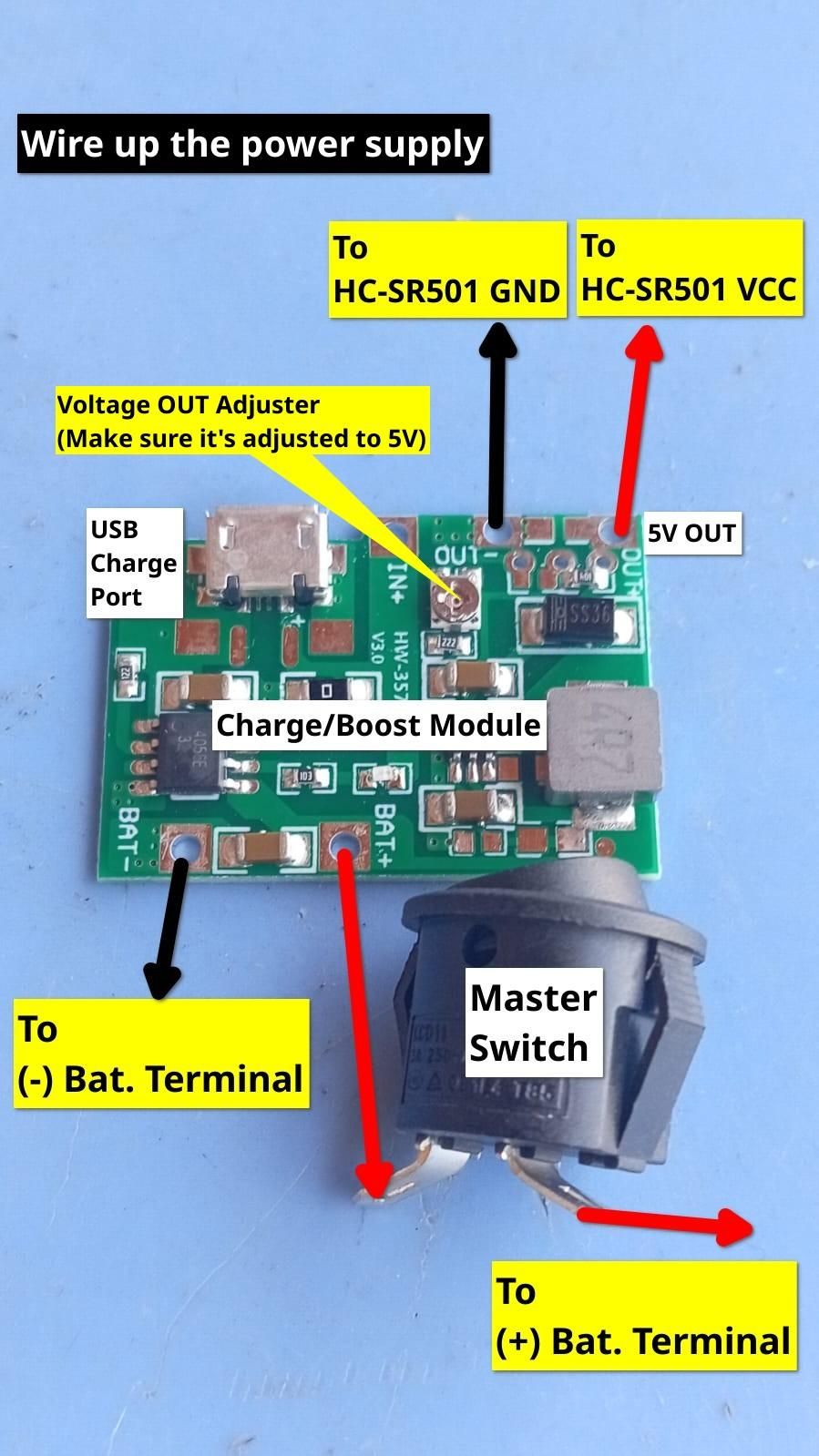
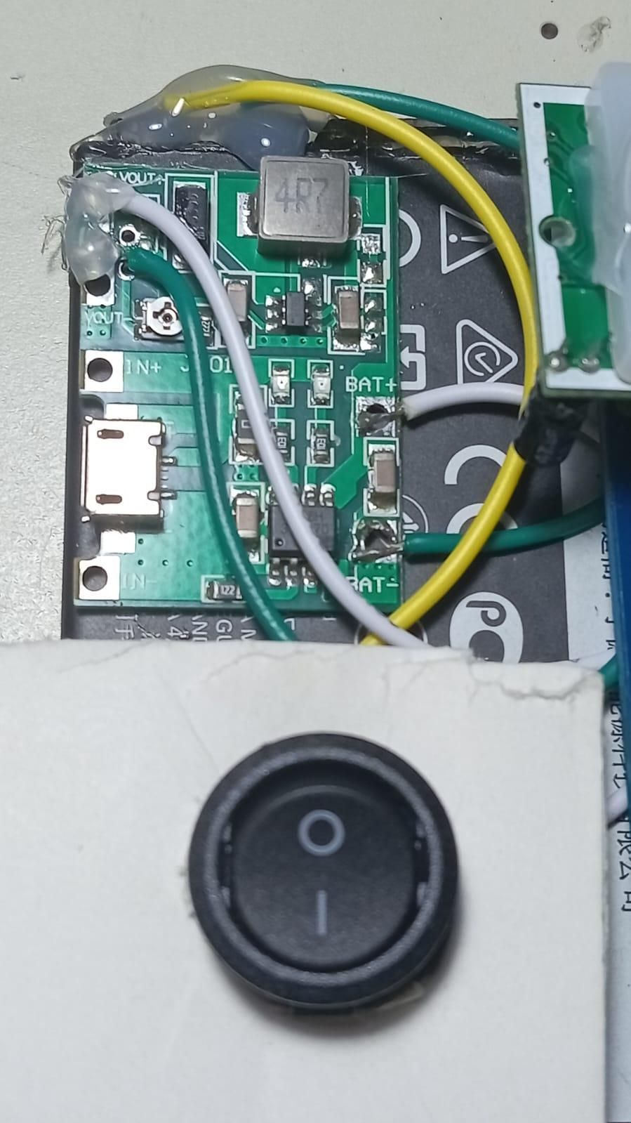
With the main circuit built, it's time to provide the power! We will wire the upcycled Li-ion battery to the charge/boost module (J5019 or HW-357), tune it to output a safe 5V, and connect it to our board.
⚠️ CRITICAL SAFETY WARNING: If your upcycled battery does not have pre-attached wires, you will have to solder directly to its metal terminals. Lithium-ion batteries are very sensitive to heat and can vent or explode if overheated. Ensure your soldering iron is hot, use flux, and do not hold the iron on the battery terminal for more than 2-3 seconds at a time. Let it cool between attempts. Alternatively, if using a cylindrical 18650 battery, you can use an 18650 battery holder and solder to the terminal breakout wires that the holder usually provides.
💡 Builder's Tip for Battery Soldering: In my experience, soldering wires to upcycled li-ion battery terminals requires some perseverance. To facilitate the process, sand the terminals with 150-180 grit sand paper and apply flux generously. If you are still struggling, you can lightly score cross hatches onto the terminal pads with a sharp box cutter or hobby knife. Apply light to moderate pressure on the cutter as you score, taking abundant care not to puncture the battery.
1. Wire the Battery & Master Switch We are adding a master switch (a simple 2-pin SPST rocker or toggle switch) between the battery and the module so you can completely shut the light down when it's not needed.
- Solder a jumper wire from the positive (+) terminal of the battery to one of the pins on your switch.
- Solder a jumper wire from the other switch pin to the BAT+ pad on the charge/boost module.
- Solder a jumper wire directly from the negative (-) terminal of the battery to the BAT- pad on the module.
(Note: Do not solder anything to the IN+ and IN- pads. Those are for charging. For most people and situations, charging via the USB port is what you want.)
2. Make Sure Boost Voltage is 5V (Do this BEFORE connecting to your main circuit.) Adjustable voltage boost modules like the ones used here sometimes ship from the factory outputting 12V or more. In my experience buying a dozen or so HW-537s and J5019s the boards have always arrived pre-adjusted to 5V. But you never know so best to check. If you were to connect the board to your main circuit while adjusted to 12V, you would fry your PIR sensor instantly.
- Flip your switch to the "ON" position.
- Get out your digital multimeter and set it to read DC Voltage. Place the red lead on the module's OUT+ pad and the black lead on the OUT- pad.
- If the reading is not 5V, use a small Phillips head screwdriver to slowly turn the voltage adjuster screw on the board (see reference photos).
- Keep turning until your multimeter reads a steady 5.0V or thereabouts. Once set, flip your power switch back to the "OFF" position.
(Note: If you get a reading of 0V, double-check that your switch is on.)
3. Connect Power to the Main Circuit Now that we know the module is outputting a safe, regulated 5V, we can connect it to the perfboard.
- Solder a jumper wire from the OUT+ (5V OUT) pad on the boost module to the female header pin on the perfboard where the HC-SR501's VCC pin goes.
- Solder a jumper wire from the OUT- pad on the boost module to the female header pin on the perfboard where the HC-SR501's GND pin goes.
The electronics are now 100% complete!
Final Assembly & Aesthetics
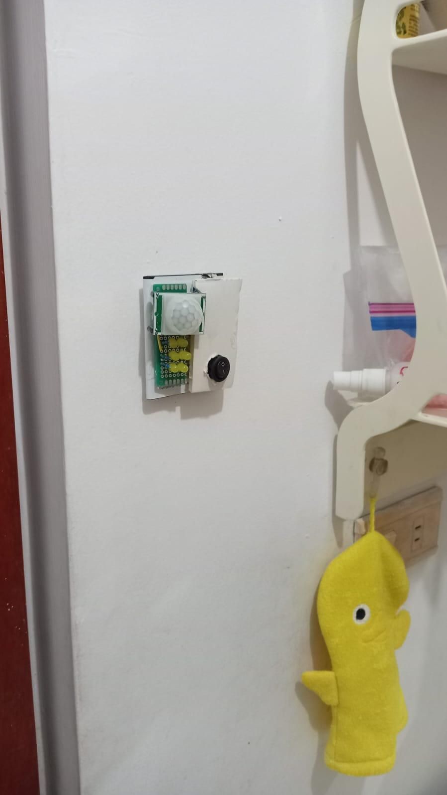
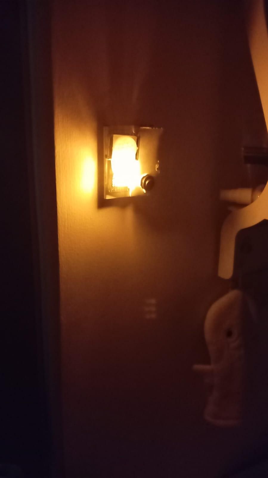
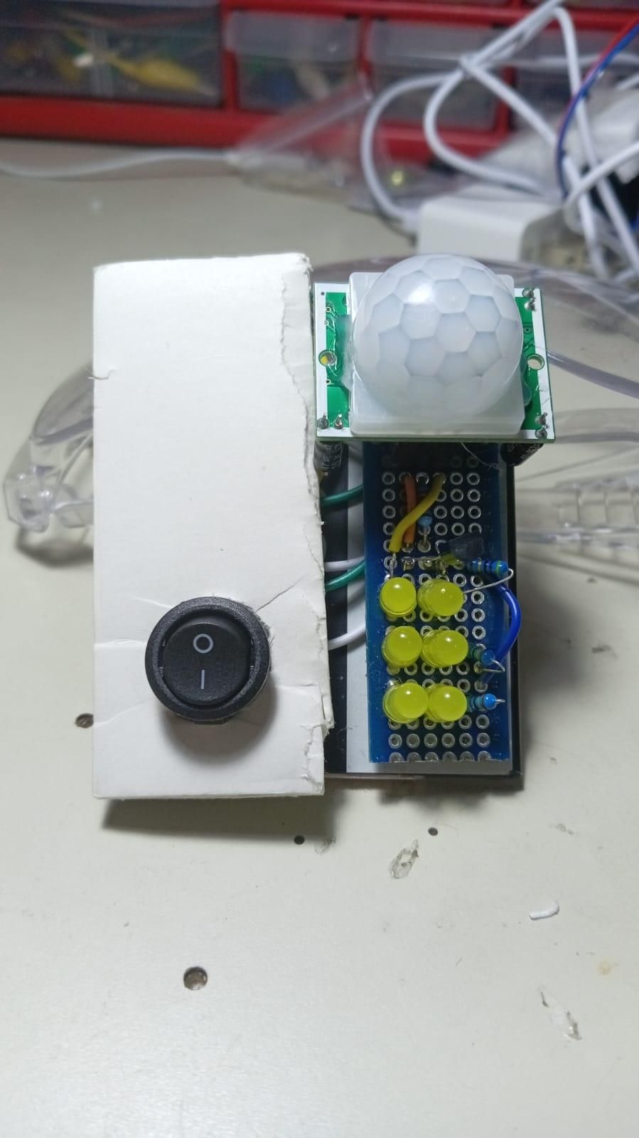
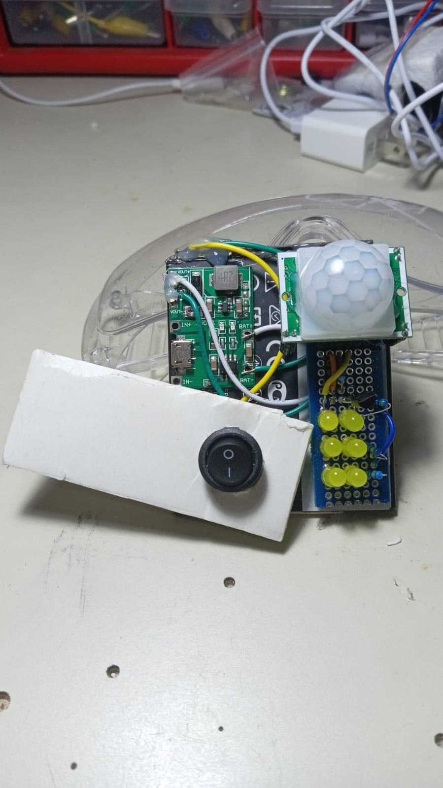
With the electronics fully tested and functioning perfectly, it is time to wrangle that sprawling mess of wires and components into a single, compact unit. Grab your hot glue gun!
1. Secure the Components Carefully fold your wires and arrange the battery, the charge/boost module, and your perfboard into a tight, compact shape. You can glue these components directly to the battery in the case of a flat cell phone battery (as in the reference photo), or glue them all down to a small backing piece of scrap cardboard or plastic in the case of cylindrical batteries. The designs in the reference photos are suggestions. I look forward to seeing what other people come up with. Whatever your design, make sure to position the charge/boost module such that the USB charge port is easily accessible.
Tip: Put some hot glue on the battery terminal solder joints to reinforce them.
2. Choose Your Aesthetic depending on where you plan to put this nightlight:
- The Unvarnished Cyberpunk Look: Leave all the wiring, the perfboard traces, and the modules completely exposed. This celebrates the upcycled nature of the build and gives the project a cool, hacked-together, tech-scavenger vibe.
- The Clean & Elegant Look: Cut a small piece of scrap foam board or cardboard to act as a sleek facade that hides (most of) the wiring. Measure and cut a hole through the facade just big enough for the master switch to poke through. The switch should fit snugly enough that it need not be glued to the facade. Then glue the bottom of the switch to the battery. Only the PIR dome, the LED array, and the switch remain visible. Note that the facade can then be swiveled about the rocker switch (if it is round) to easily reveal the "guts" of the project for inspection when necessary (see reference photos).
- Note: The switch must be fit to the facade before wiring it to the charge/boost module and battery.
- For Outdoor Deployments (Porches, Camping Trips, Etc.): you will want to develop a more rugged, hard plastic housing. Make sure to perforate a hole in the housing so that the USB charge port is easily accessible.
Astound us with your improvisations.
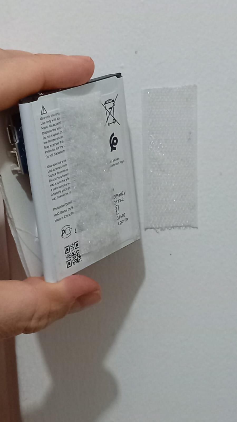
3. Mount It! Slap an adhesive velcro strip onto the flat back of your new smart nightlight (as in the reference photo). Velcro is highly recommended over permanent double-sided tape so you can easily pull the light off the wall to recharge it via the charge/boost module’s USB port.
Stick it in a dark hallway, a closet, or keep it on your bedside table for the next blackout. Let there be light!