Usb Extender Over Ethernet
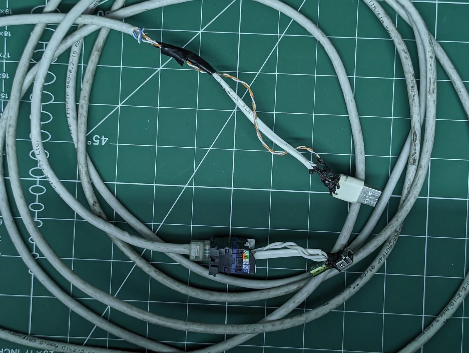
this is the story of how i stretched a usb port about 4.5 meters across the room using a leftover ethernet cable, a couple of connectors, and one fat capacitor.
i had a usb device that needed to live a few meters from the machine, and no extender lying around.
what i did have was a spare cat5e run and a box of rj45 keystone jacks.
usb really only needs four wires to work, power, ground, and the two data lines, and ethernet hands me eight, so there was plenty of copper to play with.
the plan was simple, carry usb down the ethernet cable and put a usb port back on the far end.
Supplies
my build is 4.5 meters of cat5e or cat6, solid copper, 23 awg.
i put a usb type-a male on the source end and a usb type-a female on the device end.
in the middle i used an rj45 keystone jack and a matching wall socket so the run stays modular.
across the female port i added a single 470 microfarad, 16 volt electrolytic capacitor.
that capacitor is the part most people skip, and it's the whole reason the far end stays stable under load.
for tools, i used a soldering iron, hot glue, heatshrink, a punchdown tool and a multimeter.
i'd keep a run like this under about 5 meters, past that the voltage drop starts fighting you.
The Wiring Plan
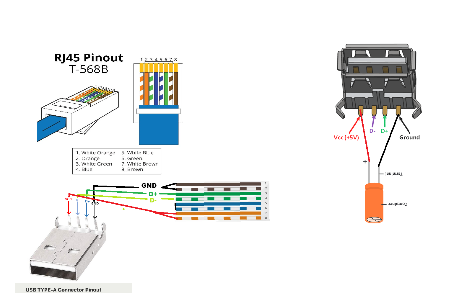
for the wiring, i mapped usb's four signals onto ethernet's eight wires using t-568b as the reference.
power and ground each get a full pair bonded together, which drops resistance and helps the 5 volts survive the trip.
the two data lines each ride a single wire, since they carry signal and not current.
the blue pair sits unused, so i just trim it back and insulate it.
here is how the eight wires land.
vcc +5v goes to orange and white/orange on pins 1 and 2, bonded as a pair.
d- goes to white/green on pin 3, a single wire.
d+ goes to green on pin 6, a single wire.
gnd goes to brown and white/brown on pins 7 and 8, bonded as a pair.
the blue and white/blue pair on pins 4 and 5 stays unused, trimmed and insulated.
Why the Capacitor Matters
for the capacitor, the thing it fixes is voltage sag.
solid copper helps, but a few meters of thin wire still drops voltage every time the device pulls current.
the cap sits right across vcc and ground at the female port and works as a small local reservoir.
when the device suddenly draws more, the cap dumps charge and smooths the dip before it turns into a brownout.
i used one cap only, positive leg to vcc, negative leg to ground, with the leads kept short.
here is roughly what i would reach for at other lengths and loads.
1 to 3 meters on 24 awg: 100 microfarad, 10 volt, up to 500 ma.
1 to 3 meters on 23 awg: 220 microfarad, 16 volt, up to 900 ma.
3 to 5 meters on 24 awg: 330 microfarad, 16 volt, up to 500 ma.
3 to 5 meters on 23 awg: 470 microfarad, 16 volt, up to 900 ma, which is my build.
5 to 7 meters on 24 awg: 470 microfarad, 16 volt, up to 300 ma.
5 to 7 meters on 23 awg: 680 microfarad, 16 volt, up to 500 ma.
7 to 10 meters on 24 awg: 1000 microfarad, 16 volt, up to 100 ma.
7 to 10 meters on 23 awg: 2200 microfarad, 25 volt, up to 300 ma.
Building the Source End
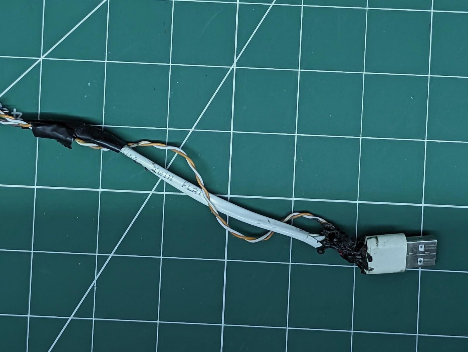
for the source end, i stripped back the outer jacket and untwisted the four pairs.
i bonded orange and white/orange together and soldered them to the vcc leg of the usb male.
white/green went to d-, and green went to d+.
i bonded brown and white/brown together for ground.
the blue pair got trimmed and tucked out of the way.
then i drowned the whole joint in hot glue and heatshrink so nothing shorts or flexes loose.
The Rj45 Join in the Middle
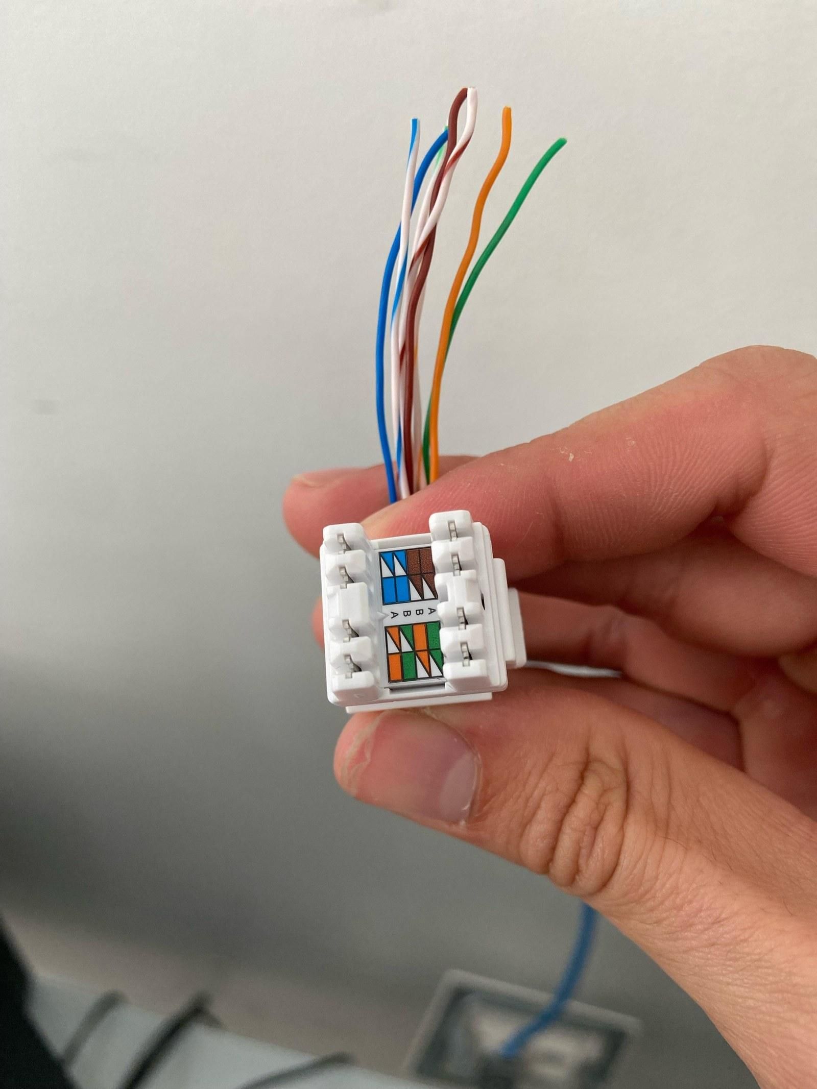
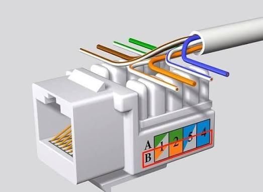
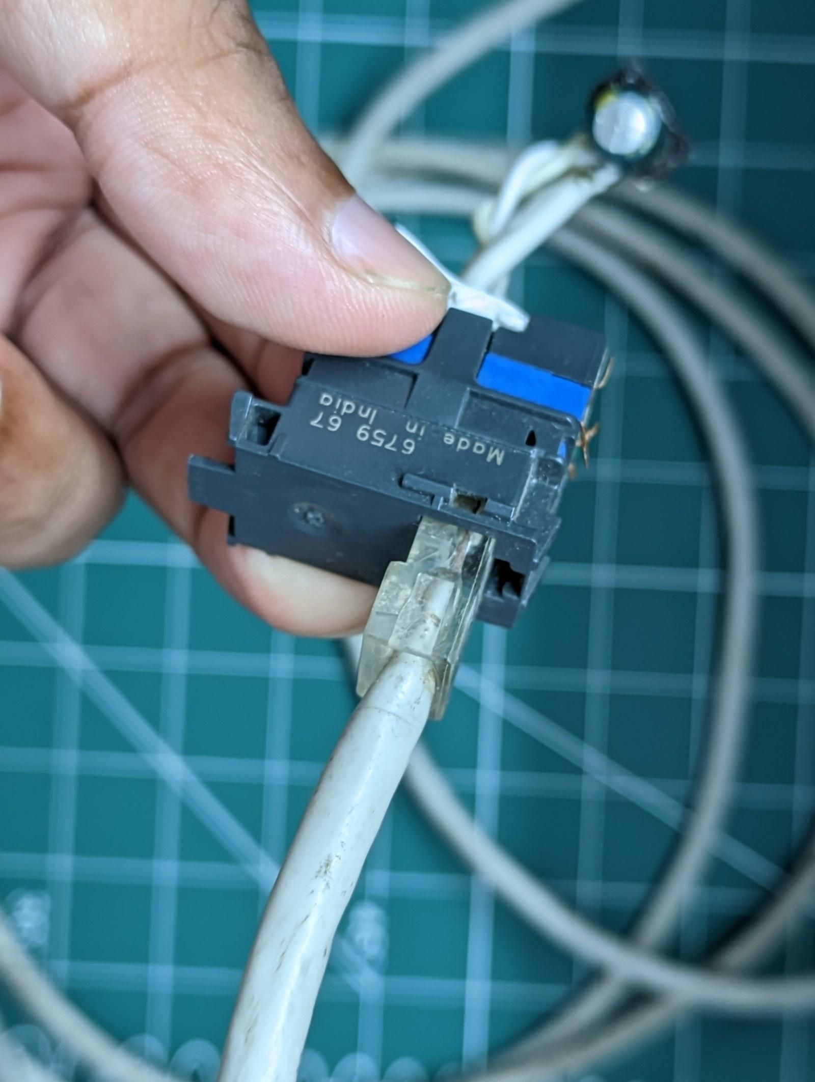
for the middle, i punched the cable down into an rj45 keystone jack in straight t-568b order.
the jack has the color map printed right on it, so most of the work is just matching wire to label.
the matching wall socket on the other side gets punched down identically, one to one.
that keeps the whole thing modular, so i can unplug it and re-route it like any normal ethernet drop.
The Device End
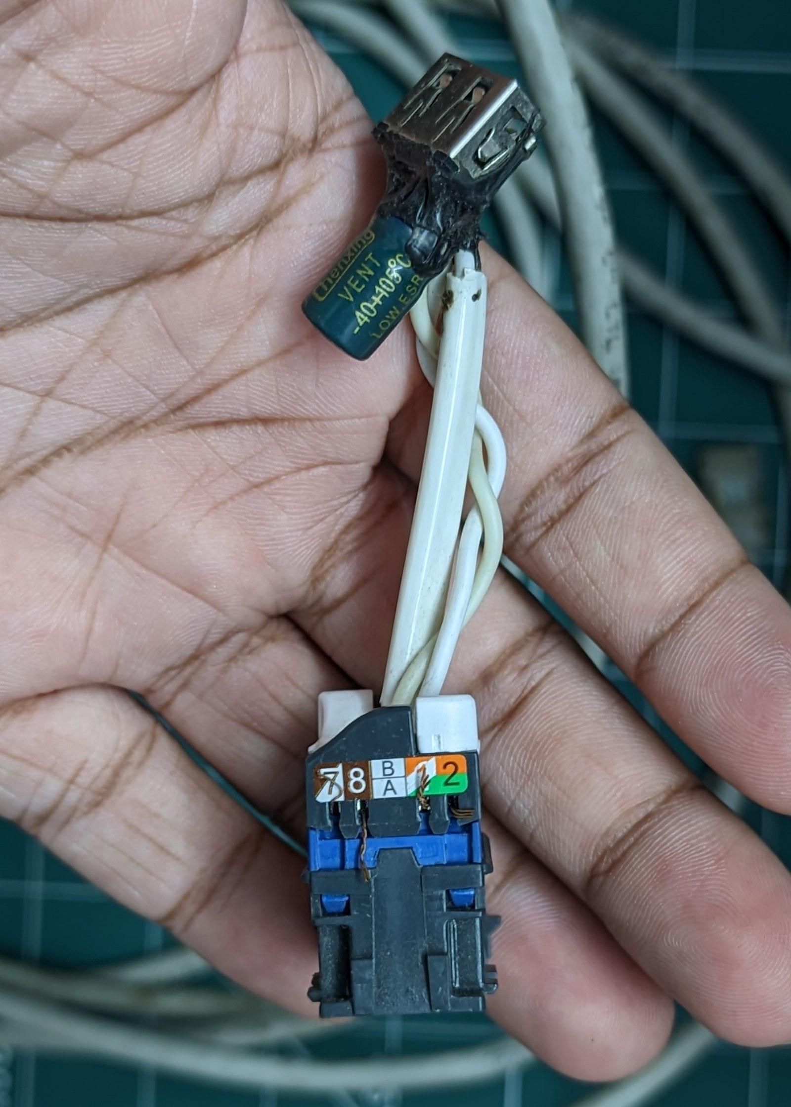
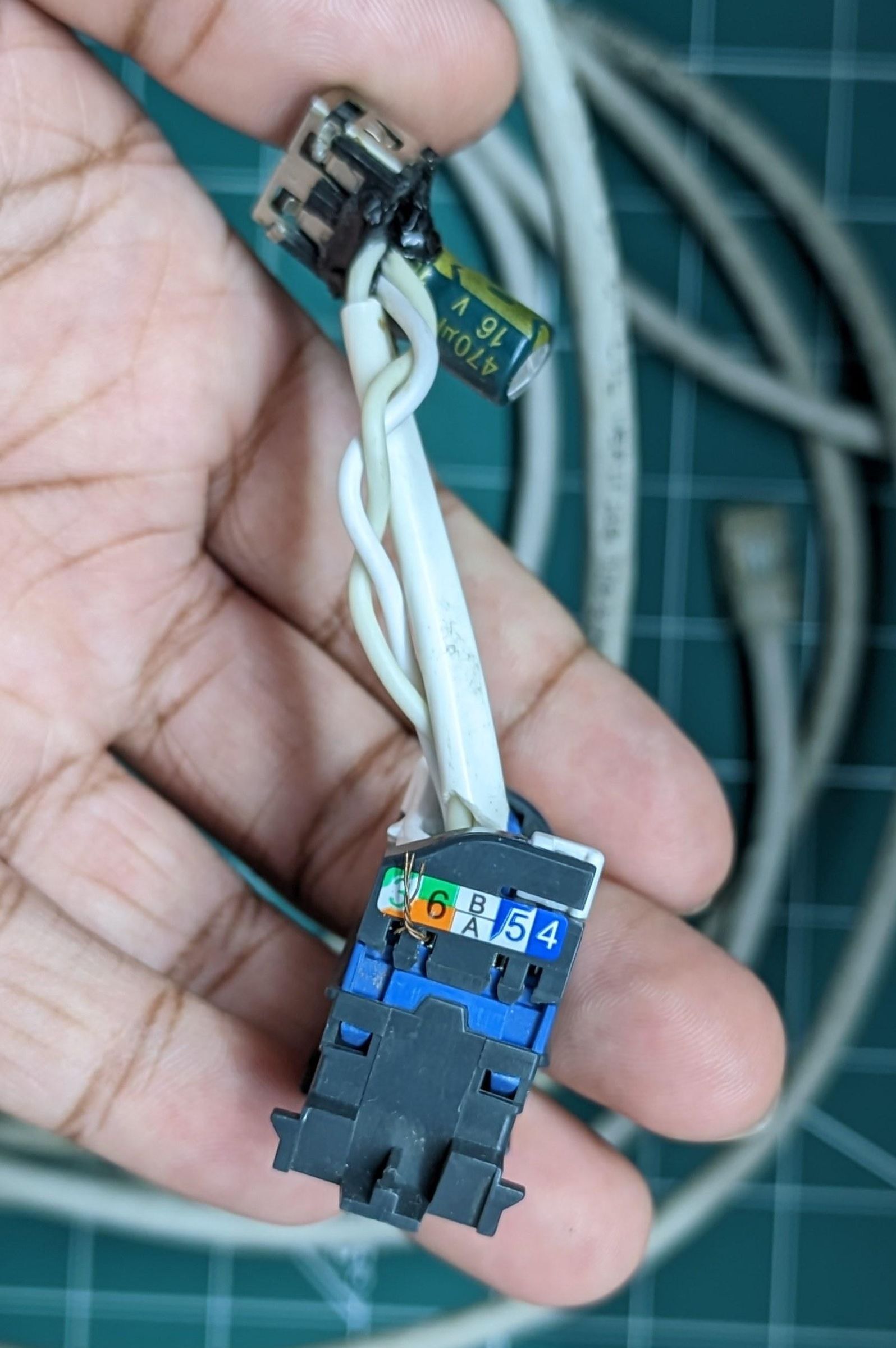
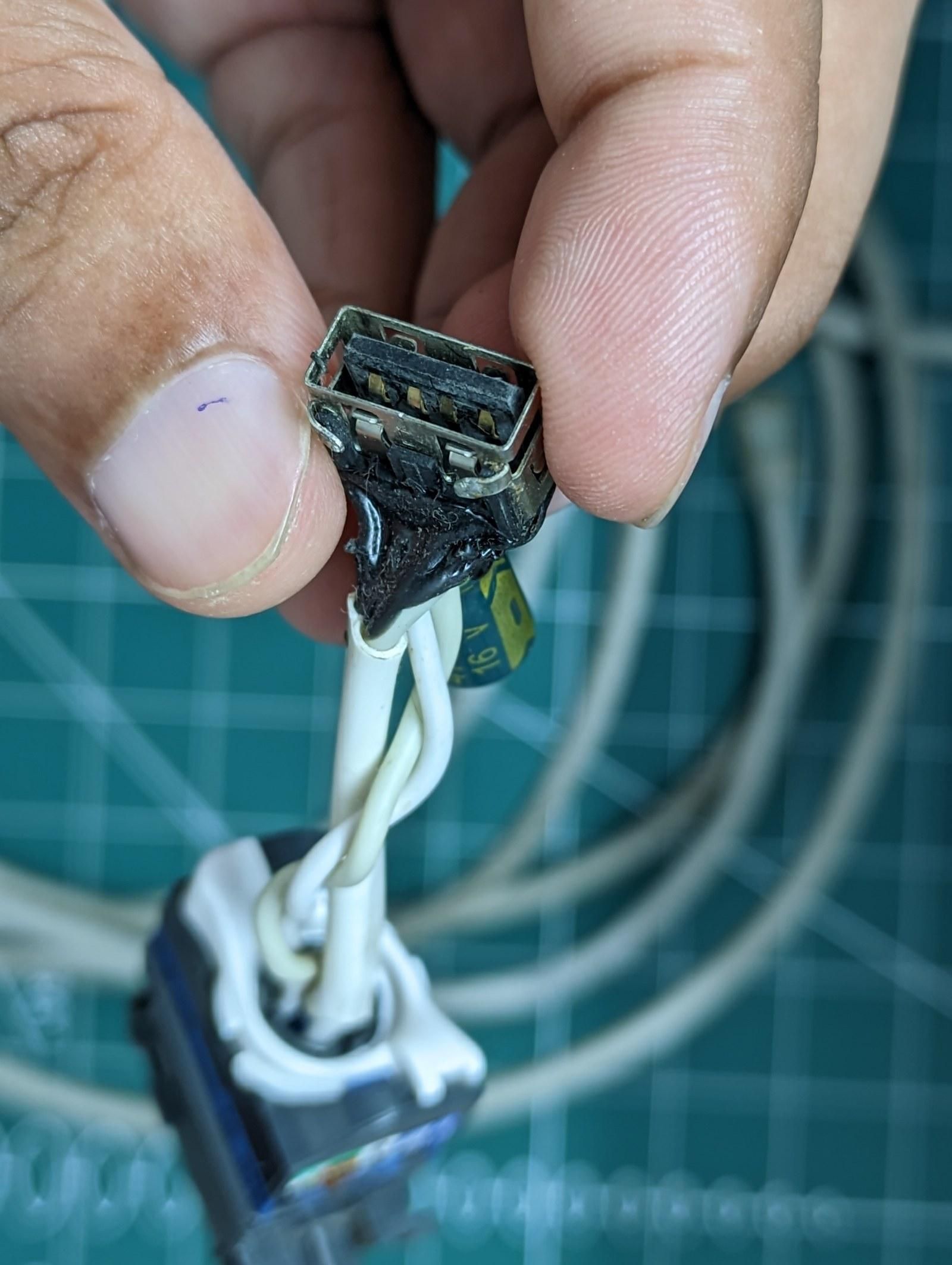
for the device end, i ran short jumpers from the socket over to the usb female port.
pins 1 and 2 bonded to vcc, pin 3 to d-, pin 6 to d+, and pins 7 and 8 bonded to ground.
then i soldered the capacitor straight across the vcc and ground nodes, positive to vcc.
i kept the cap leads short so it tucks in tight against the port.
one more round of hot glue and heatshrink, and the end was sealed.
Testing Before I Trusted It
for testing, i checked continuity first and made sure vcc and ground read open, not shorted.
then i powered it up and measured across the female port, looking for something in the 4.85 to 5.25 volt range.
i plugged in a cheap mouse before anything else, since losing a mouse beats frying something expensive.
it enumerated, held its voltage under load, and stayed stable.
Does It Work
it works.
my run is 4.5 meters of cat5e or cat6, solid copper 23 awg, with a 470 microfarad 16 volt cap across the female port.
it isn't usb 3 speeds and it isn't to spec, but for a low-power device down a long desk it does exactly the job.
if you copy this, treat it as a hobby hack, keep the load modest, and check your voltage before you plug in anything you care about.