Vasara: Surgical Robot for Autonomous Vascular Anastomosis
by akhilnagori in Circuits > Robots
1751 Views, 11 Favorites, 0 Comments
Vasara: Surgical Robot for Autonomous Vascular Anastomosis
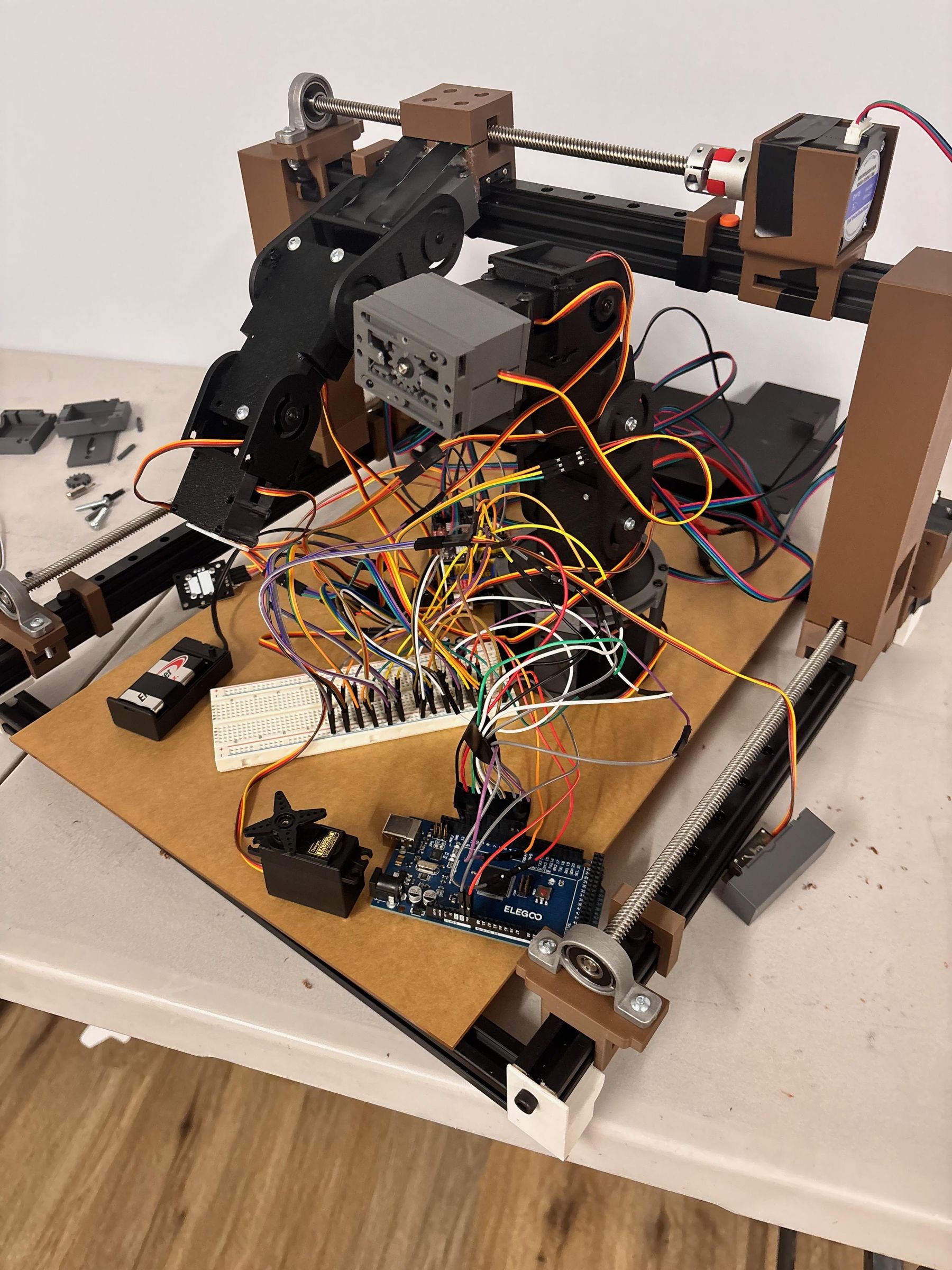
This is our gantry.
Supplies


Mechanical & structure
- 2020 aluminum extrusion frame and T-slot hardware.
- 3D printed parts for end-effector, mounts, and cable guides.
- Custom end-effector components for needle/forceps grasping.
Actuation & motion
- Stepper/servo motors (NEMA 17 recommended for gantry, precise closed-loop steppers for end-effector).
- Stepper drivers (TMC2209 or similar).
- Lead screws / linear rails / timing belts depending on design.
Electronics & control
- Main embedded controller: Jetson Orin Nano or Jetson Nano/Orin dev kit for deployment.
- Microcontroller for low-level stepper control (Arduino Mega or STM32).
- Power supply: Mean Well 24 V PSU and buck converter for logic rails.
- Limit switches, E-stop button, manual joystick.
Sensing
- High resolution overhead USB camera (Arducam or DFRobot IMX179 recommended).
- Close-up optics / USB microscope lens for fine needle tip tracking.
- Inline micro load cell + HX711 amplifier for suture tension.
- Pressure sensor and syringe pump for leak testing.
Misc
- Micro surgical instruments for fixture work (needle holder, micro forceps) and synthetic vessel phantom tubing.
- Sutures (scaled analogues for testing if real 10–0 is impractical).
- Wiring, connectors, mounting hardware
Mechanical Design
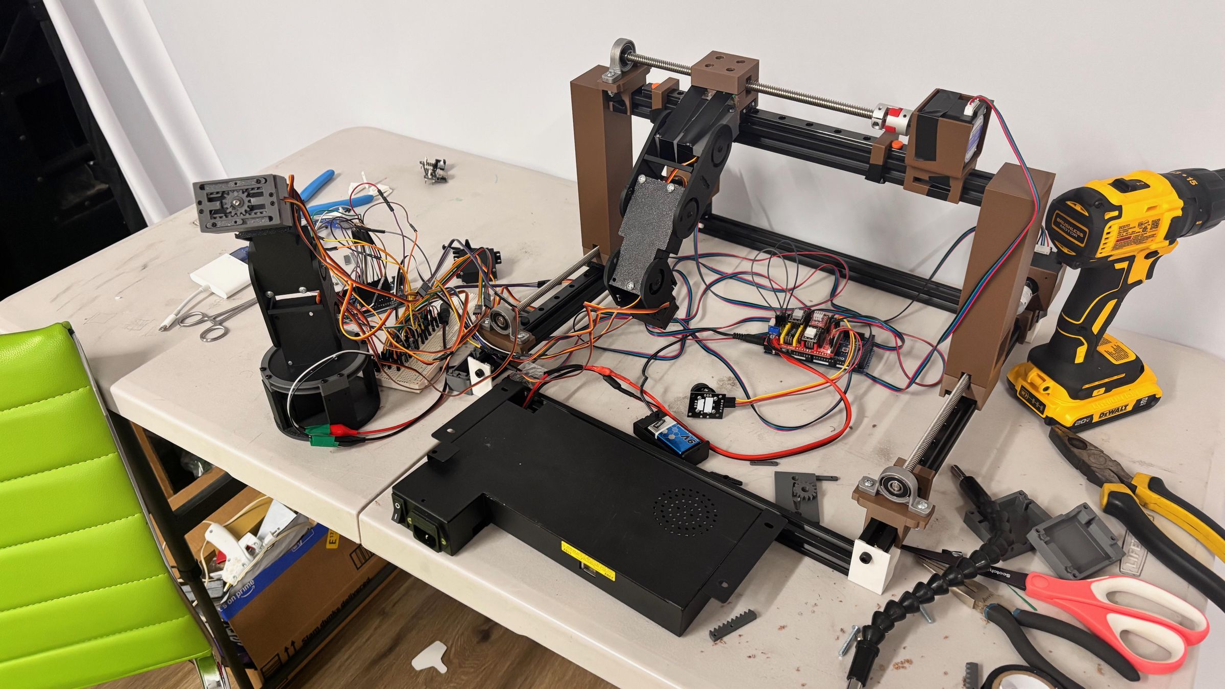
1. Frame and workspace
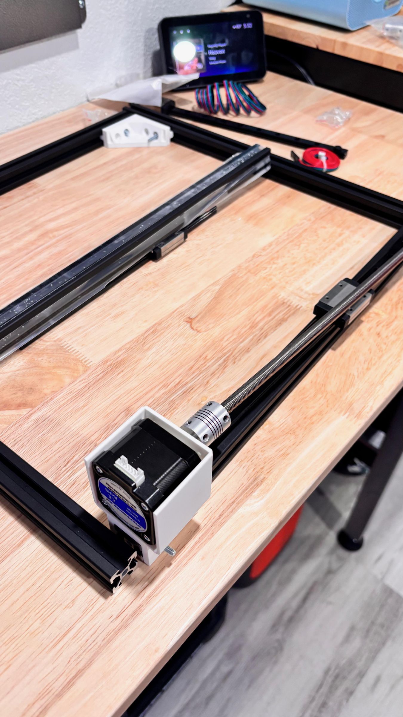
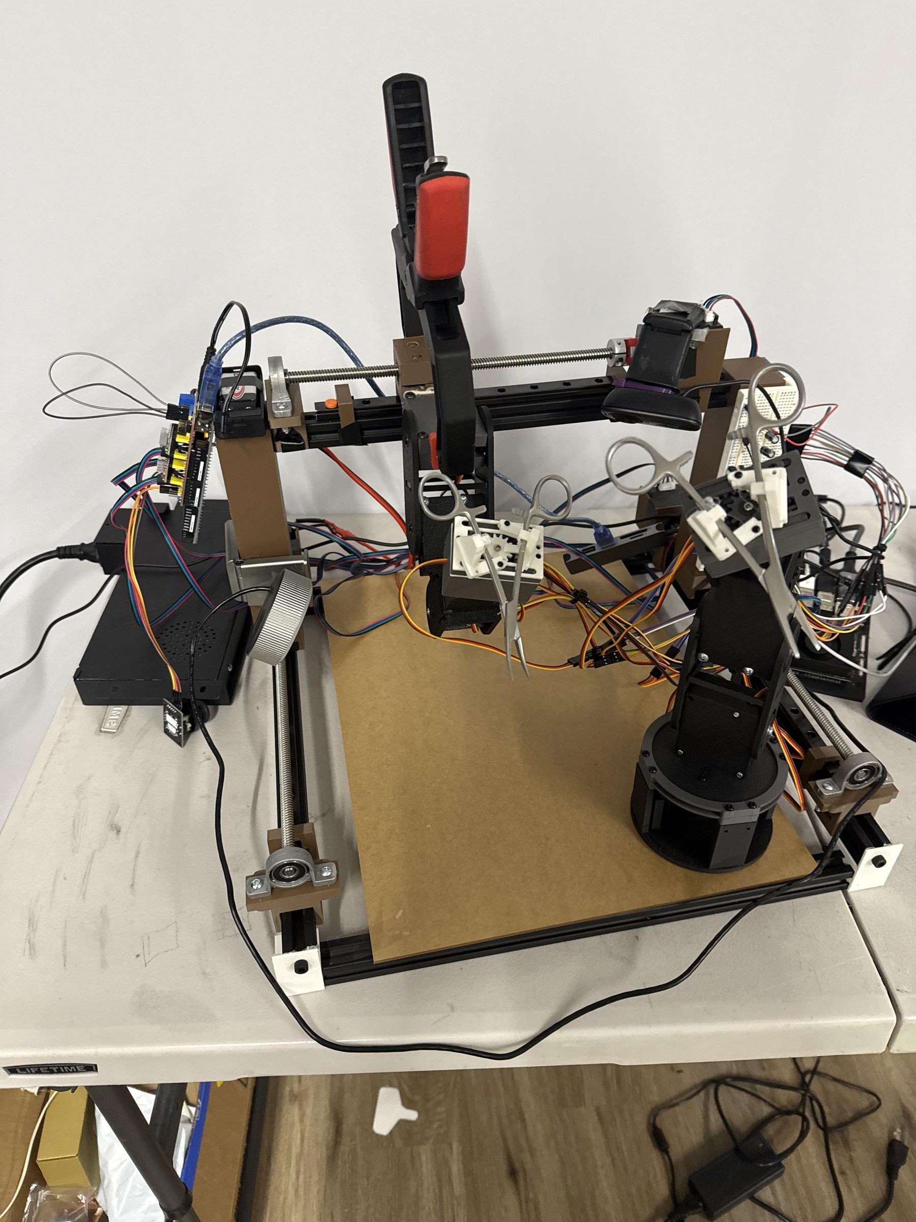
- Use 2020 aluminum T-slot extrusion for a stiff base. Keep the gantry low and rigid.
- Design a small rectangular workspace sized to hold vessel phantom clamps within a 50–150 mm radius from the needle origin. Minimizing lever arms reduces compliance.
2. Gantry & coarse motion
- Implement an XY gantry for coarse positioning using lead screws or belts. Lead screws give better repeatability; belts are faster but less precise.
- Use linear rails for guides to reduce side loads and wobble.
3. End-effector & fine orientation
- Use a 6-DOF wrist (miniature) or a custom gimbal + micro-rotation stage to control needle approach angle.
- Design the needle grasper to hold a micro needle securely without crushing. Use a small micro-needle holder geometry with repeatable seating. Include a regrasp mechanism if necessary for stitch sequences.
- Provide a suture management guide so sutures don’t tangle or change tension unexpectedly.
4. Reducing backlash and compliance
- Backlash is a major failure cause. Options:
- Use closed-loop steppers with encoders.
- Add harmonic or cycloidal gearing for the end-effector to eliminate play.
- Preload lead screws or use anti-backlash nuts.
- Use stiff, short links and minimize long unsupported sections.
5. Fixtures and phantom mounting
- Build repeatable jigs that clamp the synthetic vessel in a known orientation and tension. Use a fixture that allows small translational adjustment but locks solidly when clamped.
- Design a “vessel cradle” that mimics tissue bed geometry; keep the vessel surface level and in the camera’s ROI.
6. Assembly checklist
- Mount frame and gantry; check orthogonality with a square.
- Mount end-effector and verify mechanical range of motion covers entire phantom area.
- Install limit switches at travel ends and test.
- Wire motors to drivers with common ground. Secure cables to avoid snagging.
Electronics & Wiring
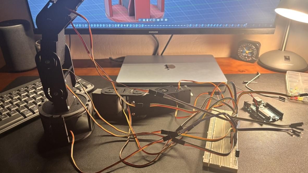

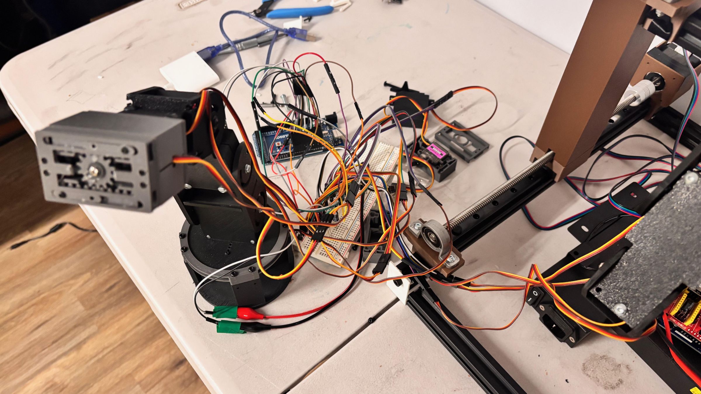
1. Power system
- Primary motor supply: 24 V DC PSU. Fuse at source; size fuse according to motor stall currents.
- Logic rail: 5 V buck converter with adequate current for microcontrollers, sensors, and cameras. Separate grounds routed to a single star ground point.
2. Motor drivers and controllers
- Use TMC2209 or similar driver modules for steppers to get quiet operation and micro-stepping. For best control of micro-motions, prefer closed-loop stepper modules with integrated encoders.
- Low-level motor commands may be generated by a microcontroller running motion planner firmware (e.g., custom Arduino / Marlin-style planner) while higher-level commands come from the Jetson via serial/ROS.
3. Sensor wiring
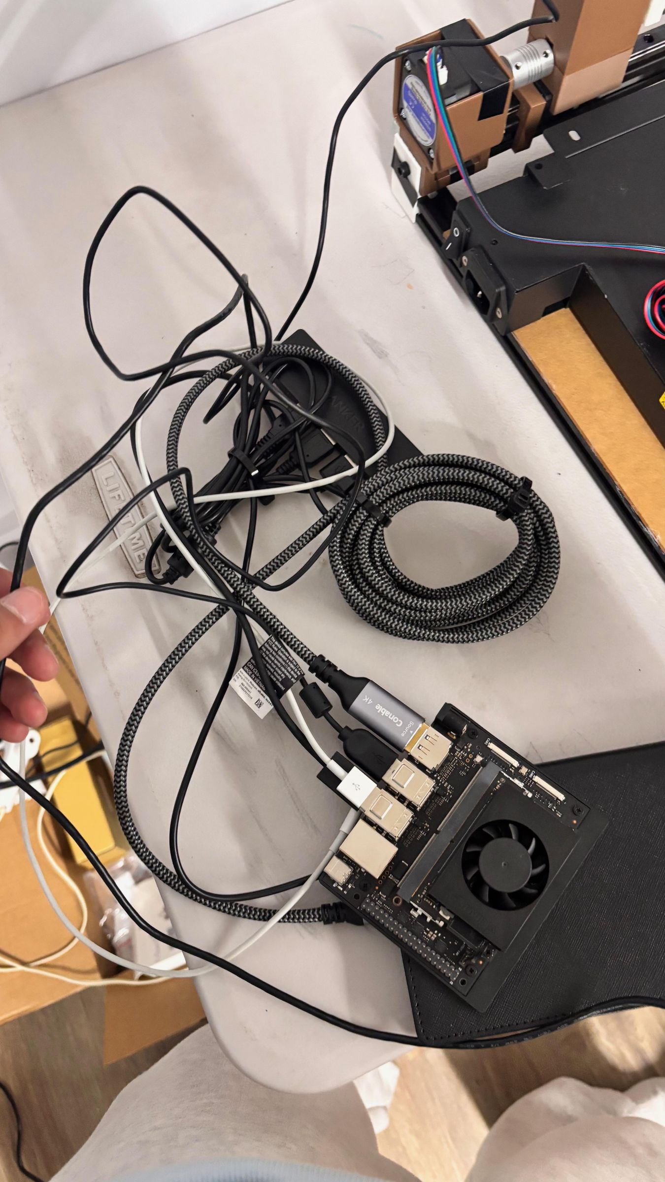
- Camera to Jetson via USB 3.0 cable; use short, shielded cables.
- Load cell to HX711 to microcontroller; route analog wiring away from high-current motor lines.
- Shield and twist sensor wires to reduce electrical noise. Add ferrite beads if required.
4. Safety and interlocks
- E-stop in series with motor power enable lines — pressing E-stop should cut motor driver enable signals and put system in safe state.
- Limit switches wired to interrupt or HALFWAY stop in low-level firmware and also monitored in high-level control.
- Manual joystick override should bypass autonomous motion; implement a “manual mode” where manual inputs drive motion directly.
Camera, Optics & Image Acquisition

1. Camera selection and optics
- Use a camera with at least 2 MP resolution and low latency (IMX179, IMX290, or similar). I used two 64 megapixel Arducams, but you can use other Jetson Nano compatible cameras. For very small features, using micro cameras is quite important
- Ring light or coaxial LED lighting reduces shadows. Using diffusers can help with training, but it all matters on your training setup, gpu, etc.
2. Calibration
- Perform standard camera intrinsics calibration (chessboard pattern) to compute focal length and distortion coefficients.
- Calibrate pixel→mm conversion at the working distance using a micro ruler or calibration grid placed at the vessel plane.
3. Image pipeline basics
- Capture frames at a consistent frame rate (≥30 fps recommended). Use timestamping at capture to synchronize with motor commands.
- Preprocess: crop to ROI, convert to grayscale, apply CLAHE if necessary, and use Gaussian blur to reduce noise.
- Needle tip & vessel detection: use either classical computer vision (edge detection + Hough transforms + template matching) or a light-weight CNN trained to output needle and vessel masks. For speed, prefer small networks (MobileNet-based) or carefully tuned CV.
Force Measurement and Sensing


For measuring suture tension, I used a small inline load cell paired with an HX711 amplifier. I mounted it directly in the suture path so that any pulling force would go through the sensor. This made it easy to capture real-time tension data during each stitch.
Before running any tests, I calibrated the load cell using small known weights and recorded the offset. I also re-zeroed it before every trial because even tiny drifts can mess up readings at this scale.
To clean up the signal, I added basic averaging in software. Without it, the readings were too noisy, especially when the motors were moving. If you’re building your own version, you can also:
- Use better shielding on wires
- Add a hardware filter
- Or upgrade to a higher precision amplifier
For control, I implemented a simple closed-loop system where the robot tries to stay within a safe tension range. If the force goes too high, it immediately stops pulling to avoid damaging the vessel.
Software Architecture
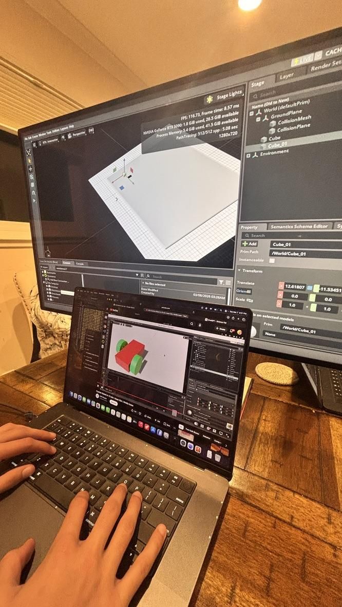
I split the system into a few main parts so it wouldn’t become a mess:
1. Low-level control
This runs on a microcontroller (I used an Arduino). It handles:
- Stepper motor control
- Limit switches
- Basic safety
2. High-level control
This runs on the main computer (I used a Jetson). It handles:
- Vision processing
- Running the AI model
- Sending movement commands
3. Communication
I connected everything using serial communication. You could also use ROS if you want something more scalable, but for me, serial was simpler and worked fine.
Simulation & Training the AI
This was one of the most important parts of the project.
I trained the system in simulation first because it’s way faster and safer than testing directly on hardware.
Environment
I used NVIDIA Isaac Sim to build a virtual version of the setup. This included:
- A simulated vessel
- A needle
- Basic physics for interaction
If you don’t want to use Isaac Sim, you could use another physics simulator, but it needs to support some level of soft-body interaction.
Other platforms include Genesis, or Unity.
Originally, I tried using a school borrowed computer with an RTX 3060, but eventually had to rent an online GPU cluster with a RTX 5090, costing only around $10-15 using Tensordock.
Setup for Training
State (what the model sees)
- Camera image (or processed features)
- Needle position
- Sometimes force data
Actions (what the model does)
- Move the needle (x, y, z, rotation)
- Open/close gripper
- Pull suture
Reward (how it learns)
I rewarded the model for:
- Hitting the correct entry point
- Completing a stitch
- Keeping spacing consistent
I penalized it for:
- Missing the target
- Applying too much force
- Damaging the vessel
Training Process
I started simple:
- Static vessel, no randomness
- Then added variation (lighting, position, stiffness)
- Slowly increased difficulty
This helped the model actually learn instead of failing constantly at the start.
Sim-to-real Transfer
To make it work in real life, I used domain randomization: this basically prevents overfitting and allows the system to work in many different conditions.
- Changed lighting
- Added noise
- Slightly varied physics
This makes the model more robust when moved to hardware.
Deploying to Hardware
Once the model worked well in simulation, I moved it to the NVIDIA Jetson Orin Nano.
To make it run fast enough:
- I optimized the model (TensorRT helps a lot)
- Reduced image size slightly
- Made sure inference stayed under ~100 ms
Before running anything real, I tested with:
- No needle movement (just predictions)
- Very slow movements
This helped avoid breaking anything early.
PS. please make sure your power supply is connected only to the CNC board on the Arduino, not directly to power and computer or microcontroller
Unfortunately, I learned this the hard way :(
Calibration (Super Important)
Go ahead and calibrate each component to its gantry, based on your dimensions.
Data Collection
Every trial, I logged:
- Target position
- Actual needle position
- Tension over time
- Whether the stitch succeeded
- Failure reason
I stored everything in CSV files so I could analyze it later.
If you’re building this, logging is one of the most important things for improving the system throughout.
Testing Procedure
Each trial followed the same process:
- Mount the vessel phantom
- Reset sensors and zero force
- Run the stitching sequence
- Record everything
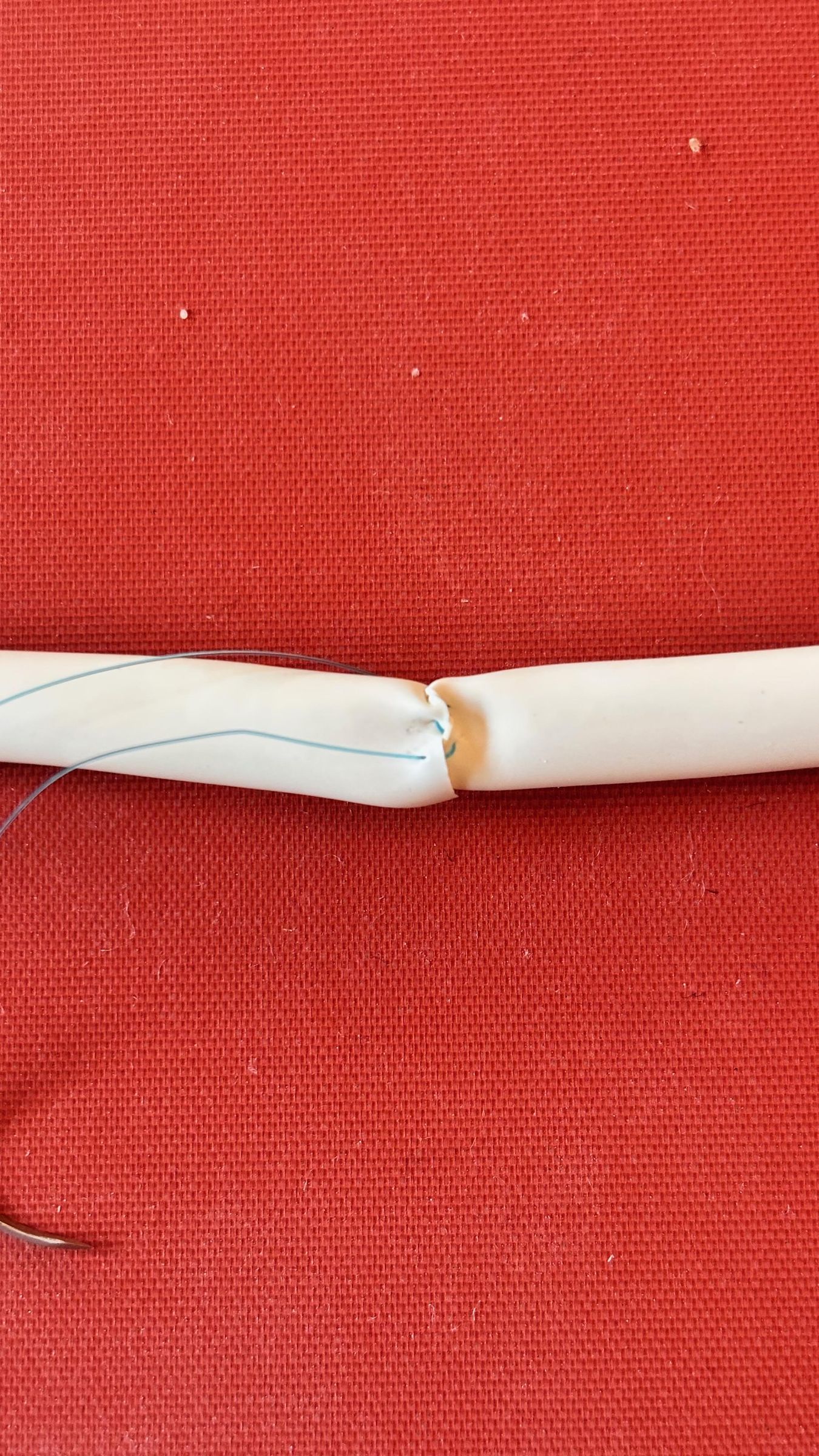
After that, I tested the quality of the anastomosis by:
- Checking spacing
- Looking for damage
- (Optional) running a leak test with water pressure
Metrics
These were the main ones I used:
- Accuracy (MRE) → how close each stitch was
- Spacing consistency → how evenly stitches were placed
- Tension control → whether force stayed in safe range
- Success rate → full procedure completed correctly
- Latency → how fast the system reacts
Simulation results were very high (97%), but hardware dropped (72%) mainly due to mechanical issues.
Currently, I built the entire system using mg946r servos and sg90 servos for the gripper, but these have significant levels of backlash causing issues later.
Files
Cad Files Attached: