Vehicle Driver Monitoring and Safety Alert System

by tumipham07 in Circuits > Arduino

43 Views, 1 Favorites, 0 Comments

Vehicle Driver Monitoring and Safety Alert System

z7874913665286_a58b5a20463c290afd54b9a11bf0b499.jpg

This project is a fault-tolerant vehicle safety monitoring system developed using an Arduino Nano 33 IoT, Raspberry Pi, MQTT communication, and Node-RED dashboard monitoring. The system is designed to detect dangerous driving behaviour and nearby obstacles using sensors including an MPU6050 accelerometer/gyroscope and HC-SR04 ultrasonic sensor.

The Arduino continuously monitors vehicle movement data such as tilt, swerving behaviour, and obstacle distance. These sensor values are transmitted in real time to a Raspberry Pi through MQTT communication, where they are visualised on a Node-RED dashboard using charts, gauges, and alerts. The dashboard also supports remote LED (auto mode) warning control, where you can practice by extending to buzzer (auto mode) control.

To improve system reliability, fault tolerance was implemented using local autonomous warning behaviour and offline event buffering. If the network or MQTT broker disconnects, the Arduino continues operating independently and stores warning events locally before automatically retransmitting them when the connection is restored.

Supplies

arduino nano 33 iot.jpg
mpu6050.jpg
spi4.jpg
ultrasonic.jpg

Hardware Components

  1. Arduino Nano 33 IoT
  2. Raspberry Pi
  3. Monitor
  4. MPU6050 Accelerometer and Gyroscope Sensor
  5. HC-SR04 Ultrasonic Distance Sensor
  6. BH1750 Light Sensor
  7. LED
  8. Passive Buzzer
  9. Breadboard
  10. Jumper wires
  11. USB cable
  12. WiFi connection

Software and Services

  1. Arduino IDE
  2. Raspberry Pi OS
  3. Mosquitto MQTT Broker
  4. Node-RED
  5. MQTT protocol
  6. Gmail SMTP / Node-RED Email node

Libraries Used

  1. WiFiNINA
  2. ArduinoMqttClient
  3. Wire.h
  4. Adafruit_MPU6050
  5. Adafruit_Sensor
  6. BH1750

System Features

  1. Real-time vehicle movement monitoring
  2. Obstacle distance detection
  3. MQTT-based two-way communication
  4. Node-RED dashboard visualization
  5. Remote LED and buzzer control
  6. Email alert notifications
  7. Fault-tolerant offline event buffering

Understand the System Design

flow diagram.jpg

Before building the project, we first plan the overall system architecture. The system uses an Arduino Nano 33 IoT as the on-board sensing unit and a Raspberry Pi as the monitoring server. The Arduino reads data from the MPU6050 motion sensor and HC-SR04 ultrasonic sensor to detect dangerous movement, tilt, and nearby obstacles. It then sends sensor data and alert messages to the Raspberry Pi using MQTT.


The Raspberry Pi runs Mosquitto MQTT Broker and Node-RED. Node-RED displays live charts, manages dashboard controls, and sends email alerts when danger is detected. The dashboard also allows the user to remotely enable or disable the LED and buzzer warnings. This creates two-way communication between the Arduino and Raspberry Pi.

Hardware Connection

hardware connection.jpg

The hardware components were connected using a breadboard and jumper wires. The MPU6050 sensor was connected through I2C communication to detect vehicle tilt and acceleration, while the HC-SR04 ultrasonic sensor was used to measure front obstacle distance. A LED and passive buzzer were added as local warning outputs to alert dangerous driving conditions.


The Arduino Nano 33 IoT was used as the main controller because it supports built-in WiFi communication for MQTT networking. The Raspberry Pi was prepared as the central monitoring server to run Mosquitto MQTT Broker and Node-RED dashboard services.


After completing the hardware connections, the sensors and warning devices were tested individually before integrating MQTT communication and dashboard monitoring.


The table below shows the main hardware connections used in the prototype.


Sensor testing photo

Test the Sensors and Local Warning Outputs

Before adding MQTT communication, let's test the hardware locally on the Arduino. This helped confirm that the sensors and warning outputs were working correctly before connecting the system to the Raspberry Pi.


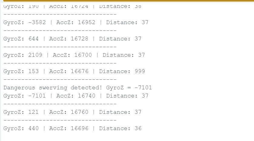
First, let's test the MPU6050 sensor by printing the GyroZ and AccZ values to the Serial Monitor. GyroZ was used to observe sudden swerving movement, while AccZ was used to observe tilt behaviour.

#include <Wire.h>

#define MPU_ADDR 0x68

int16_t AccX, AccY, AccZ;
int16_t GyroX, GyroY, GyroZ;

void setup() {
Serial.begin(9600);
delay(2000);

Wire.begin();

// Wake up MPU6050
Wire.beginTransmission(MPU_ADDR);
Wire.write(0x6B);
Wire.write(0x00);
Wire.endTransmission(true);

Serial.println("MPU6050 test started");
}

void loop() {

Wire.beginTransmission(MPU_ADDR);
Wire.write(0x3B);
Wire.endTransmission(false);

Wire.requestFrom(MPU_ADDR, 14, true);

AccX = (Wire.read() << 8) | Wire.read();
AccY = (Wire.read() << 8) | Wire.read();
AccZ = (Wire.read() << 8) | Wire.read();

Wire.read();
Wire.read();

GyroX = (Wire.read() << 8) | Wire.read();
GyroY = (Wire.read() << 8) | Wire.read();
GyroZ = (Wire.read() << 8) | Wire.read();

Serial.print("AccZ: ");
Serial.print(AccZ);

Serial.print(" | GyroZ: ");
Serial.println(GyroZ);

delay(300);
}


Your Serial Monitor should be like this:

Test MPU6050 Sensor


Then, let's test the HC-SR04 ultrasonic sensor by printing the measured distance in centimetres.

#define TRIG_PIN 9
#define ECHO_PIN 10

void setup() {
Serial.begin(9600);

pinMode(TRIG_PIN, OUTPUT);
pinMode(ECHO_PIN, INPUT);

Serial.println("HC-SR04 ultrasonic sensor test started");
}

void loop() {

// Send trigger pulse
digitalWrite(TRIG_PIN, LOW);
delayMicroseconds(2);

digitalWrite(TRIG_PIN, HIGH);
delayMicroseconds(10);

digitalWrite(TRIG_PIN, LOW);

// Measure echo duration
long duration = pulseIn(ECHO_PIN, HIGH);

// Convert to distance
int distance = duration * 0.034 / 2;

Serial.print("Distance: ");
Serial.print(distance);
Serial.println(" cm");

delay(500);
}

The sensor should return different distance values depending on how close the object was placed to the front of the sensor.


Test Ultrasonic sensor


After confirming that the sensor readings changed correctly, I added the LED and buzzer warning logic. When dangerous swerving, tilt, or a nearby obstacle was detected, the LED and buzzer were activated locally. This step was important because it proved that the Arduino could respond to danger independently before MQTT communication was added.

Test Local Warning Outputs

After testing the sensors individually, the LED and passive buzzer warning outputs were added to create a local safety alert system. The warning devices were programmed to activate whenever dangerous movement, tilt, or nearby obstacles were detected.


Threshold values were introduced to determine when the warning system should activate. During testing, the LED and buzzer responded immediately when the MPU6050 detected strong swerving or tilt movement, or when the ultrasonic sensor detected an object too close to the front of the system.


This step was important because it allowed the Arduino Nano 33 IoT to continue providing local safety warnings even without network or Raspberry Pi communication.


#include <Wire.h>

#define MPU_ADDR 0x68

// Ultrasonic sensor pins
#define TRIG_PIN 9
#define ECHO_PIN 10

// Warning output pins
#define BUZZER_PIN 4
#define LED_PIN 2

// MPU6050 values
int16_t AccX, AccY, AccZ;
int16_t GyroX, GyroY, GyroZ;

// Threshold values
int swerveThreshold = 7000;
int tiltThreshold = 15000;
int distanceThreshold = 20;

void setup() {

Serial.begin(9600);
delay(2000);

Wire.begin();

// Wake up MPU6050
Wire.beginTransmission(MPU_ADDR);
Wire.write(0x6B);
Wire.write(0x00);
Wire.endTransmission(true);

// Ultrasonic pins
pinMode(TRIG_PIN, OUTPUT);
pinMode(ECHO_PIN, INPUT);

// Warning outputs
pinMode(LED_PIN, OUTPUT);
pinMode(BUZZER_PIN, OUTPUT);

Serial.println("Local warning output test started");
}

void loop() {

// Read MPU6050 values
readMPU();

// Read ultrasonic distance
int distance = getDistance();

bool danger = false;


// Swerving detection
if (abs(GyroZ) > swerveThreshold) {

danger = true;

Serial.print("Dangerous swerving detected! GyroZ = ");
Serial.println(GyroZ);
}


// Tilt detection
if (AccZ < tiltThreshold) {

danger = true;

Serial.print("Dangerous tilt detected! AccZ = ");
Serial.println(AccZ);
}


// Obstacle detection
if (distance != 999 && distance < distanceThreshold) {

danger = true;

Serial.print("Obstacle too close! Distance = ");
Serial.print(distance);
Serial.println(" cm");
}


// Activate warning outputs
if (danger) {

digitalWrite(LED_PIN, HIGH);

tone(BUZZER_PIN, 1000);

} else {

digitalWrite(LED_PIN, LOW);

noTone(BUZZER_PIN);
}

// Print live sensor values
Serial.print("GyroZ: ");
Serial.print(GyroZ);

Serial.print(" | AccZ: ");
Serial.print(AccZ);

Serial.print(" | Distance: ");
Serial.println(distance);

Serial.println("--------------------------------");

delay(300);
}


// Read MPU6050 sensor values
void readMPU() {

Wire.beginTransmission(MPU_ADDR);
Wire.write(0x3B);
Wire.endTransmission(false);

Wire.requestFrom(MPU_ADDR, 14, true);

AccX = (Wire.read() << 8) | Wire.read();
AccY = (Wire.read() << 8) | Wire.read();
AccZ = (Wire.read() << 8) | Wire.read();

// Skip temperature values
Wire.read();
Wire.read();

GyroX = (Wire.read() << 8) | Wire.read();
GyroY = (Wire.read() << 8) | Wire.read();
GyroZ = (Wire.read() << 8) | Wire.read();
}

// Read ultrasonic sensor distance
int getDistance() {

// Send trigger pulse
digitalWrite(TRIG_PIN, LOW);
delayMicroseconds(2);

digitalWrite(TRIG_PIN, HIGH);
delayMicroseconds(10);

digitalWrite(TRIG_PIN, LOW);

// Measure echo duration
long duration = pulseIn(ECHO_PIN, HIGH, 30000);

// No echo received
if (duration == 0) {
return 999;
}

// Convert duration to distance
int distance = duration * 0.034 / 2;

// Ignore invalid readings
if (distance > 400 || distance < 1) {
return 999;
}

return distance;
}

Sensor testing photo

Sensor testing photo


Sensor testing photo

Set Up Raspberry Pi and Install MQTT Broker

rpi.jpg

Before connecting the Arduino to MQTT, the Raspberry Pi need to prepared to host the Mosquitto MQTT Broker and Node-RED dashboard services.


First, Raspberry Pi OS was installed and the Raspberry Pi was connected to the same WiFi network as the Arduino Nano 33 IoT. After updating the system packages, Mosquitto MQTT Broker and Mosquitto Clients were installed to support MQTT communication between devices.


Node-RED was also installed to provide dashboard monitoring, real-time charts, email alerts, and remote warning control.

Update Raspberry Pi Packages

Open terminal on Raspberry Pi

First, the Raspberry Pi system packages should be updated.

sudo apt update

This command refreshes the Raspberry Pi package list.

sudo apt upgrade -y

This command upgrades installed software packages to the latest version.


Install Mosquitto MQTT Broker

Next, installing Mosquitto MQTT Broker and MQTT client tools.

sudo apt install mosquitto mosquitto-clients -y

Explanation:

  1. mosquitto installs the MQTT broker service.
  2. mosquitto-clients installs MQTT testing tools such as publish and subscribe commands.
  3. -y automatically confirms installation.


Enable and Start Mosquitto

The broker service is enabled and started using the following commands.

sudo systemctl enable mosquitto

This command allows Mosquitto to automatically start whenever the Raspberry Pi boots.

sudo systemctl start mosquitto

This command starts the MQTT broker service immediately.


Check MQTT Broker Status

The following command was used to confirm that the broker was running correctly.

sudo systemctl status mosquitto

If the broker is active, the terminal should display:

active (running)


Sensor testing photoFind Raspberry Pi IP Address

The Raspberry Pi IP address is required later in the Arduino MQTT code.

hostname -I

Example output:

192.168.20.211

Sensor testing photo

This IP address becomes the MQTT broker address inside the Arduino program.


Install Node-RED

Node-RED is installed using the official installation script.

bash <(curl -sL https://raw.githubusercontent.com/node-red/linux-installers/master/deb/update-nodejs-and-nodered)

Explanation:

  1. Downloads and installs Node.js and Node-RED.
  2. Automatically configures required dependencies.

Enable Node-RED Service

sudo systemctl enable nodered.service

This command allows Node-RED to automatically start when the Raspberry Pi boots.


Start Node-RED

node-red-start

This command starts the Node-RED server.


Open Node-RED Editor

After Node-RED starts, open a browser and enter:

http://YOUR_RPI_IP:1880

Example:

http://192.168.20.211:1880

This opens the Node-RED editor interface where the dashboard and MQTT flows are created.


Install Node-RED Dashboard

The Node-RED dashboard package is installed to create gauges, charts, switches, and dashboard widgets.

In the Raspberry Pi terminal, run:

cd ~/.node-red

Then install the dashboard package:

npm install node-red-dashboard

Restart Node-RED:

node-red-restart

After this, dashboard nodes such as gauges, charts, switches, and text displays become available in Node-RED.


Open the Node-RED Dashboard Interface

To access the live monitoring dashboard, add /ui to the Node-RED address:

http://YOUR_RPI_IP:1880/ui

Example:

http://192.168.20.211:1880/ui

The dashboard interface displays (after the Node-RED dashboard flow has been fully configured and deployed in the following steps):

  1. Real-time GyroZ chart
  2. AccZ monitoring chart
  3. Obstacle distance chart
  4. LED warning control switch
  5. Buzzer warning control switch
  6. Email alert enable/disable switch

This dashboard allows users to monitor sensor values and remotely control warning systems in real time through MQTT communication.


Configure MQTT Authentication

To make the MQTT broker more secure, a username and password can be created for Mosquitto.

sudo mosquitto_passwd -c /etc/mosquitto/passwd your_username

Replace your_username with the username you want to use. After running this command, the terminal will ask you to enter and confirm a password.

After creating the password file, restart Mosquitto:

sudo systemctl restart mosquitto


Test MQTT Publish and Subscribe

Before connecting the Arduino, MQTT communication can be tested directly on the Raspberry Pi.

Open one terminal window and run:

mosquitto_sub -h localhost -t "car/#"

This command subscribes to all MQTT topics that start with car/ and waits for incoming messages.

Open a second terminal window and run:

mosquitto_pub -h localhost -t "car/test" -m "MQTT test successful"

This command publishes a test message to the car/test topic.

If MQTT is working correctly, the first terminal should display:

MQTT test successful

Configure MQTT Communication

After the Raspberry Pi and Mosquitto MQTT Broker were prepared, the Arduino Nano 33 IoT need vto be updated to connect to the broker through WiFi. In this step, MQTT isused to send live sensor data from the Arduino to the Raspberry Pi and to send control commands from Node-RED back to the Arduino.


This step creates two-way communication between the two devices. The Arduino publishes GyroZ, AccZ, distance, and alert messages, while also subscribing to LED and buzzer control topics.


Sensor testing photo


To update the previous code, we add the WiFiNINA and ArduinoMqttClient libraries, configure the Raspberry Pi broker IP address, created MQTT topics, and added functions to connect to WiFi, connect to MQTT, and publish sensor values.


**(Before uploading the code, update the WiFi name, WiFi password, Raspberry Pi IP address, MQTT username, and MQTT password to match your own setup.)**

#include <WiFiNINA.h>
#include <ArduinoMqttClient.h>
#include <Wire.h>

// =====================================================
// WiFi details
// Update these values to match your own WiFi network
// =====================================================
char ssid[] = "YOUR_WIFI_NAME";
char pass[] = "YOUR_WIFI_PASSWORD";

// =====================================================
// MQTT broker details
// The broker is running on the Raspberry Pi
// Replace this IP address with your Raspberry Pi IP
// =====================================================
char broker[] = "YOUR_RPI_IP_ADDRESS";
int port = 1883;

// MQTT username and password
char mqttUser[] = "YOUR_MQTT_USERNAME";
char mqttPass[] = "YOUR_MQTT_PASSWORD";

// =====================================================
// MQTT topics used by the Arduino to publish data
// =====================================================
char topicGyroZ[] = "car/gyroZ"; // Swerving/rotation value
char topicAccZ[] = "car/accZ"; // Tilt-related value
char topicDistance[] = "car/distance"; // Front obstacle distance
char topicAlert[] = "car/alert"; // Danger warning message

// =====================================================
// MQTT topics used by Raspberry Pi / Node-RED to control Arduino
// These topics allow two-way communication
// =====================================================
char topicLedControl[] = "car/control/led"; // Remote LED warning control
char topicBuzzerControl[] = "car/control/buzzer"; // Remote buzzer warning control

// =====================================================
// WiFi and MQTT client objects
// =====================================================
WiFiClient wifiClient;
MqttClient mqttClient(wifiClient);

// =====================================================
// Hardware pin definitions
// =====================================================
#define MPU_ADDR 0x68
#define TRIG_PIN 9
#define ECHO_PIN 10
#define BUZZER_PIN 4
#define LED_PIN 2

// =====================================================
// Sensor value variables
// =====================================================
int16_t AccX, AccY, AccZ;
int16_t GyroX, GyroY, GyroZ;

// =====================================================
// Threshold values
// These values can be adjusted during testing
// =====================================================
int swerveThreshold = 7000;
int tiltThreshold = 15000;
int distanceThreshold = 20;

// =====================================================
// Remote warning control states
// These values can be changed from the Node-RED dashboard
// =====================================================
bool ledEnabled = true;
bool buzzerEnabled = true;

void setup() {
Serial.begin(9600);
delay(2000);

Wire.begin();

// Wake up the MPU6050 sensor
Wire.beginTransmission(MPU_ADDR);
Wire.write(0x6B);
Wire.write(0x00);
Wire.endTransmission(true);

// Configure ultrasonic sensor pins
pinMode(TRIG_PIN, OUTPUT);
pinMode(ECHO_PIN, INPUT);

// Configure warning output pins
pinMode(BUZZER_PIN, OUTPUT);
pinMode(LED_PIN, OUTPUT);

// Connect to WiFi and MQTT broker
connectWiFi();
connectMQTT();

Serial.println("MQTT sensor monitoring system started");
}

void loop() {
// Reconnect WiFi if connection is lost
if (WiFi.status() != WL_CONNECTED) {
connectWiFi();
}

// Reconnect MQTT if broker connection is lost
if (!mqttClient.connected()) {
connectMQTT();
}

// Keep MQTT connection active
// This also allows Arduino to receive control messages
mqttClient.poll();

// Read sensor values
readMPU();
int distance = getDistance();

// Keep MQTT responsive while running sensor logic
mqttClient.poll();

// Publish live values to MQTT topics
publishLiveData(distance);

bool danger = false;
String alertMessage = "";

// Detect dangerous swerving using GyroZ
if (abs(GyroZ) > swerveThreshold) {
danger = true;
alertMessage += "Dangerous swerving detected! GyroZ=" + String(GyroZ) + " | ";
}

// Detect dangerous tilt using AccZ
if (AccZ < tiltThreshold) {
danger = true;
alertMessage += "Dangerous tilt detected! AccZ=" + String(AccZ) + " | ";
}

// Detect nearby front obstacle
if (distance != 999 && distance < distanceThreshold) {
danger = true;
alertMessage += "Front obstacle too close! Distance=" + String(distance) + "cm | ";
}

// Local warning response
if (danger) {
// LED only turns on if it is enabled from dashboard
if (ledEnabled) {
digitalWrite(LED_PIN, HIGH);
} else {
digitalWrite(LED_PIN, LOW);
}

// Buzzer only turns on if it is enabled from dashboard
if (buzzerEnabled) {
tone(BUZZER_PIN, 1000);
} else {
noTone(BUZZER_PIN);
}

// Send warning message to MQTT
publishAlert(alertMessage);
} else {
digitalWrite(LED_PIN, LOW);
noTone(BUZZER_PIN);
}

// Print values for debugging
Serial.print("GyroZ: ");
Serial.print(GyroZ);

Serial.print(" | AccZ: ");
Serial.print(AccZ);

Serial.print(" | Distance: ");
Serial.println(distance);

delay(300);
}

// =====================================================
// Connect Arduino to WiFi
// =====================================================
void connectWiFi() {
Serial.print("Connecting to WiFi");

while (WiFi.begin(ssid, pass) != WL_CONNECTED) {
Serial.print(".");
delay(1000);
}

Serial.println();
Serial.println("WiFi connected");
}

// =====================================================
// Connect Arduino to MQTT broker on Raspberry Pi
// =====================================================
void connectMQTT() {
Serial.print("Connecting to MQTT broker");

mqttClient.setUsernamePassword(mqttUser, mqttPass);
mqttClient.setId("arduino-car-monitor-01");

// Register callback function to receive MQTT control messages
mqttClient.onMessage(onMqttMessage);

while (!mqttClient.connect(broker, port)) {
Serial.print(".");
delay(1000);
}

Serial.println();
Serial.println("MQTT connected");

// Subscribe to control topics from Raspberry Pi / Node-RED
mqttClient.subscribe(topicLedControl);
mqttClient.subscribe(topicBuzzerControl);

Serial.println("Subscribed to LED and buzzer control topics");
}

// =====================================================
// Handle incoming MQTT messages from Raspberry Pi / Node-RED
// This enables two-way communication
// =====================================================
void onMqttMessage(int messageSize) {
String topic = mqttClient.messageTopic();
String message = "";

while (mqttClient.available()) {
message += (char)mqttClient.read();
}

message.trim();

Serial.print("MQTT topic received: ");
Serial.println(topic);

Serial.print("MQTT message received: ");
Serial.println(message);

// Remote LED warning control
if (topic == String(topicLedControl)) {
if (message == "LED_ON") {
ledEnabled = true;
Serial.println("LED warning enabled");
} else if (message == "LED_OFF") {
ledEnabled = false;
digitalWrite(LED_PIN, LOW);
Serial.println("LED warning disabled");
}
}

// Remote buzzer warning control
if (topic == String(topicBuzzerControl)) {
if (message == "BUZZER_ON") {
buzzerEnabled = true;
Serial.println("Buzzer warning enabled");
} else if (message == "BUZZER_OFF") {
buzzerEnabled = false;
noTone(BUZZER_PIN);
Serial.println("Buzzer warning disabled");
}
}
}

// =====================================================
// Publish live sensor values to MQTT topics
// =====================================================
void publishLiveData(int distance) {
mqttClient.beginMessage(topicGyroZ);
mqttClient.print(GyroZ);
mqttClient.endMessage();

mqttClient.beginMessage(topicAccZ);
mqttClient.print(AccZ);
mqttClient.endMessage();

mqttClient.beginMessage(topicDistance);
mqttClient.print(distance);
mqttClient.endMessage();
}

// =====================================================
// Publish danger alert message to MQTT
// =====================================================
void publishAlert(String message) {
mqttClient.beginMessage(topicAlert);
mqttClient.print(message);
mqttClient.endMessage();
}

// =====================================================
// Read MPU6050 accelerometer and gyroscope values
// =====================================================
void readMPU() {
Wire.beginTransmission(MPU_ADDR);
Wire.write(0x3B);
Wire.endTransmission(false);

Wire.requestFrom(MPU_ADDR, 14, true);

AccX = (Wire.read() << 8) | Wire.read();
AccY = (Wire.read() << 8) | Wire.read();
AccZ = (Wire.read() << 8) | Wire.read();

// Skip temperature values
Wire.read();
Wire.read();

GyroX = (Wire.read() << 8) | Wire.read();
GyroY = (Wire.read() << 8) | Wire.read();
GyroZ = (Wire.read() << 8) | Wire.read();
}

// =====================================================
// Read distance from ultrasonic sensor
// 999 is returned when no valid echo is detected
// =====================================================
int getDistance() {
digitalWrite(TRIG_PIN, LOW);
delayMicroseconds(2);

digitalWrite(TRIG_PIN, HIGH);
delayMicroseconds(10);

digitalWrite(TRIG_PIN, LOW);

long duration = pulseIn(ECHO_PIN, HIGH, 30000);

if (duration == 0) {
return 999;
}

int distance = duration * 0.034 / 2;

if (distance > 400 || distance < 1) {
return 999;
}

return distance;
}

After uploading this version, open the Serial Monitor. You should see:

Sensor testing photo


The Arduino now connects to the Raspberry Pi Mosquitto MQTT Broker and publishes live sensor values to different MQTT topics. It also publishes danger alerts when swerving, tilt, or nearby obstacle conditions are detected.

Test Live MQTT Data Communication

Before building the Node-RED dashboard, MQTT communication between the Arduino Nano 33 IoT and Raspberry Pi should be tested to confirm that sensor data could be published and received correctly in real time.


In this step, MQTTX is used as a testing client to monitor live MQTT topics from the Arduino. The Arduino continuously published GyroZ, AccZ, distance, and alert messages to the Mosquitto MQTT Broker running on the Raspberry Pi.


This step confirmed that:

  1. the Arduino successfully connected to WiFi
  2. the Arduino successfully connected to the MQTT broker
  3. sensor values were being published correctly
  4. the Raspberry Pi MQTT broker was receiving live data


Install MQTTX

Open a browser and download MQTTX from:

MQTTX Official Website

Or directly download from GitHub:

MQTTX GitHub Releases

Install MQTTX on the Raspberry Pi or another computer connected to the same WiFi network.


Open MQTTX

Method 1: Open from Raspberry Pi desktop

Menu → Internet → MQTTX

Method 2: Open from terminal

mqttx

If using AppImage:

chmod +x MQTTX.AppImage
./MQTTX.AppImage


Create MQTT Connection

Host: YOUR_RPI_IP
Port: 1883
Username: your_username
Password: your_password


Example:

Host: 192.168.20.211
Port: 1883


Subscribe to all project topics:

car/#

This allows MQTTX to display all messages under the car/ topic group.


Verify Live Messages

When the Arduino is running, MQTTX should show live messages such as:

car/gyroZ
car/accZ
car/distance
car/alert

If these values appear and update in real time, the Arduino and Raspberry Pi MQTT communication is working correctly.

Sensor testing photo

Build the Node-RED Dashboard

After confirming that MQTT communication was working correctly, a Node-RED dashboard was created to visualize live sensor data and remotely control the warning systems.

The dashboard uses:

  1. MQTT input nodes to receive live sensor values
  2. Dashboard chart nodes to display data
  3. Dashboard switch nodes for remote control
  4. MQTT output nodes to send commands back to the Arduino
  5. Email nodes for danger notifications

Open Node-RED Editor

Open a browser and enter:

http://YOUR_RPI_IP:1880

Example:

http://192.168.20.211:1880


Add MQTT Input Nodes

On the left Node-RED panel, drag four MQTT input nodes into the workspace.

ouble-click the first MQTT node.

Configure:

Server: localhost:1883
Topic: car/gyroZ
Output: a parsed string
Name: GyroZ Data
Sensor testing photo

Click:

Done


Repeat for:

car/accZ
car/distance
car/alert

These nodes subscribe to live MQTT data published by the Arduino Nano 33 IoT.


Configure Dashboard Charts

From the dashboard section, drag three chart nodes into the workspace.

Connect:

car/gyroZ → chart
car/accZ → chart
car/distance → chart


Configure chart names:

Vehicle Swerving Level Over Time
Vehicle Tilt Variation Over Time
Front Distance Over Time


Configure:

X-axis: time
Y-axis: automatic


Click:

Done


Configure LED Control Switch

From the dashboard section on the left panel, drag a ui_switch node into the workspace.

Double-click the switch node and configure:

Group: Vehicle Safety Dashboard
Label: LED AUTO MODE
On Payload: (string) LED_ON
Off Payload: (string) LED_OFF
Topic: car/control/led


Click:

Done


Next, drag an mqtt out node into the workspace.

Connect:

LED AUTO MODE switch → mqtt out


Double-click the MQTT output node and configure:

Server: localhost:1883
Topic: leave blank
QoS: 0
Retain: false


Click:

Done

When the dashboard switch is turned ON or OFF, MQTT commands are sent to the Arduino Nano 33 IoT to enable or disable the LED warning system.


Configure Buzzer Control Switch

Drag another ui_switch node into the workspace.

Double-click the node and configure:

Group: Vehicle Safety Dashboard
Label: BUZZER AUTO MODE
On Payload:(string) BUZZER_ON
Off Payload: (string)BUZZER_OFF
Topic: car/control/buzzer


Click:

Done


Drag another mqtt out node into the workspace.

Connect:

BUZZER AUTO MODE switch → mqtt out


Configure the MQTT output node:

Server: localhost:1883
Topic: leave blank
QoS: 0
Retain: false

When the switch is changed on the dashboard, MQTT commands are sent back to the Arduino to enable or disable the buzzer warning behaviour.


Configure Email Alert Flow

The email alert system sends warning emails whenever danger is detected.

First, drag an mqtt in node into the workspace.

Configure:

Server: localhost:1883
Topic: car/alert
Output: a parsed string
Name: Danger Alerts


Click:

Done

Next, drag a delay node into the workspace.


Connect:

Danger Alerts → delay


Configure the delay node:

Rate limit: 1 message every 10 seconds
Drop intermediate messages: enabled

This helps prevent excessive repeated email notifications.


Configure Email Alert Switch

Drag a ui_switch node into the workspace.

Configure:

Label: EMAIL ALERT
On Payload: true
Off Payload: false


Next, drag a change node into the workspace.

Connect:

EMAIL ALERT switch → change node


Configure the change node:

Set flow.emailEnabled to msg.payload

This stores the dashboard switch state inside Node-RED.


Add Email Filter

Drag a switch node into the workspace.

Connect:

delay → switch


Configure:

Property: flow.emailEnabled
Rule: is true

This allows emails to be sent only when the EMAIL ALERT switch is enabled.


Configure Email Node

Drag an email node into the workspace.

Connect:

switch → email


Configure:

Server: smtp.gmail.com
Port: 465
Userid: your_email@gmail.com
Password: your_app_password
Secure connection: enabled
To: your_email@gmail.com
Subject: Vehicle Safety Alert


Click:

Done

When danger is detected and the EMAIL ALERT switch is enabled, Node-RED sends a warning email notification.


Deploy Dashboard

After all flows are configured, click:

Deploy

in the top-right corner of Node-RED.

If the deployment is successful, Node-RED will display:

Successfully deployed
Sensor testing photo


Open Dashboard UI

Open a web browser and enter:

http://YOUR_RPI_IP:1880/ui

Example:

http://192.168.20.211:1880/ui

The dashboard should now display:

  1. live sensor charts
  2. warning alerts
  3. LED control switch
  4. buzzer control switch
  5. email alert switch

The dashboard can now monitor the vehicle safety system and remotely control warning behaviours through MQTT communication.

Sensor testing photo

Test the Complete System

After building the dashboard and configuring MQTT communication, the full system is tested to verify that all components were working together correctly. This step checks real-time monitoring, warning detection, remote control, and email alert functionality.

Test Real-Time Dashboard Monitoring

Move or tilt the MPU6050 sensor and place objects in front of the ultrasonic sensor.

Verify that:

  1. GyroZ chart updates
  2. AccZ chart updates
  3. Distance chart updates
  4. warning alerts appear

Expected result:

Live values should continuously change and be recorded on the dashboard.


Test LED Warning Control

Turn the dashboard LED switch OFF.

Verify:

  1. Arduino receives:
LED_OFF
  1. LED no longer activates during danger detection

Turn the switch ON again.

Verify:

  1. Arduino receives:
LED_ON
  1. LED warning behaviour returns

Test Buzzer Warning Control

Turn the dashboard buzzer switch OFF.

Verify:

  1. Arduino receives:
BUZZER_OFF

  1. buzzer no longer activates during danger detection

Turn the switch ON again.

Verify:

  1. Arduino receives:
BUZZER_ON

  1. buzzer warning behaviour returns

Test Email Alert System

Enable the EMAIL ALERT switch.

Trigger dangerous movement or obstacle detection.

Verify:

  1. Node-RED receives:
car/alert

  1. warning email is sent successfully

Disable the EMAIL ALERT switch.

Trigger danger again.

Verify:

  1. dashboard still displays alerts
  2. no email is sent

Test MQTT Communication

Open MQTTX and subscribe to:

car/#

Verify that live messages appear:

car/gyroZ
car/accZ
car/distance
car/alert
car/control/led
car/control/buzzer

This confirms successful two-way MQTT communication between the Arduino and Raspberry Pi.

Sensor testing photoSensor testing photo


Implement Fault-Tolerant Behaviour

In this step, the Arduino code was updated to make the system more reliable when MQTT or WiFi communication fails. Instead of completely stopping when the Raspberry Pi or MQTT broker is unavailable, the Arduino continues reading sensor values, detecting danger, and activating the local LED and buzzer warnings.

The main improvement in this step is offline event buffering. When danger is detected but MQTT is disconnected, the Arduino temporarily stores the warning message in a local array. After the MQTT connection is restored, the stored warning events are automatically published back to the Raspberry Pi.


What Was Added

  1. Automatic WiFi reconnection
  2. Automatic MQTT reconnection
  3. Offline warning event buffer
  4. Store-and-forward behaviour
  5. Local LED and buzzer warning during communication failure
  6. Resending saved danger events after reconnection

Update the previous Arduino MQTT code with the following version:

#include <WiFiNINA.h>
#include <ArduinoMqttClient.h>
#include <Wire.h>

// =====================================================
// WiFi details
// Update these values to match your own WiFi network
// =====================================================
char ssid[] = "NetComm 2248";
char pass[] = "ASHcSvdYSt377ed8";

// =====================================================
// MQTT broker details
// The broker is running on the Raspberry Pi
// Replace this IP address with your Raspberry Pi IP
// =====================================================
char broker[] = "192.168.20.211";
int port = 1883;

// MQTT username and password
char mqttUser[] = "tumi";
char mqttPass[] = "Tumi230307@";


// =====================================================
// MQTT topics used by the Arduino to publish data
// =====================================================
char topicGyroZ[] = "car/gyroZ"; // Swerving/rotation value
char topicAccZ[] = "car/accZ"; // Tilt-related value
char topicDistance[] = "car/distance"; // Front obstacle distance
char topicAlert[] = "car/alert"; // Danger warning message

// =====================================================
// MQTT topics used by Raspberry Pi / Node-RED to control Arduino
// These topics allow two-way communication
// =====================================================
char topicLedControl[] = "car/control/led"; // Remote LED warning control
char topicBuzzerControl[] = "car/control/buzzer"; // Remote buzzer warning control

// =====================================================
// WiFi and MQTT client objects
// =====================================================
WiFiClient wifiClient;
MqttClient mqttClient(wifiClient);

// =====================================================
// Hardware pin definitions
// =====================================================
#define MPU_ADDR 0x68
#define TRIG_PIN 9
#define ECHO_PIN 10
#define BUZZER_PIN 5
#define LED_PIN 2

// =====================================================
// Sensor value variables
// =====================================================
int16_t AccX, AccY, AccZ;
int16_t GyroX, GyroY, GyroZ;

// =====================================================
// Threshold values
// These values can be adjusted during testing
// =====================================================
int swerveThreshold = 7000;
int tiltThreshold = 15000;
int distanceThreshold = 20;

// =====================================================
// Remote warning control states
// These values can be changed from the Node-RED dashboard
// =====================================================
bool ledEnabled = true;
bool buzzerEnabled = true;

// =====================================================
// Offline buffer for fault tolerance
// Stores danger events when MQTT connection is unavailable
// =====================================================
#define MAX_BUFFER 30
String offlineEvents[MAX_BUFFER];
int bufferCount = 0;

// Reconnect timing
unsigned long lastMqttReconnectAttempt = 0;
const unsigned long mqttReconnectInterval = 5000;

void setup() {
Serial.begin(9600);
delay(2000);

Wire.begin();

// Wake up the MPU6050 sensor
Wire.beginTransmission(MPU_ADDR);
Wire.write(0x6B);
Wire.write(0x00);
Wire.endTransmission(true);

// Configure ultrasonic sensor pins
pinMode(TRIG_PIN, OUTPUT);
pinMode(ECHO_PIN, INPUT);

// Configure warning output pins
pinMode(BUZZER_PIN, OUTPUT);
pinMode(LED_PIN, OUTPUT);

// Connect to WiFi and MQTT broker
connectWiFi();

// Set MQTT login and callback once
mqttClient.setUsernamePassword(mqttUser, mqttPass);
mqttClient.setId("arduino-car-monitor-01");
mqttClient.onMessage(onMqttMessage);

// Try MQTT once at startup
connectMQTTNonBlocking();

Serial.println("MQTT sensor monitoring system started");
}

void loop() {
// Reconnect WiFi if connection is lost
if (WiFi.status() != WL_CONNECTED) {
connectWiFi();
}

// Try MQTT reconnect every few seconds, but do not block sensor monitoring
if (!mqttClient.connected()) {
unsigned long now = millis();
if (now - lastMqttReconnectAttempt >= mqttReconnectInterval) {
lastMqttReconnectAttempt = now;
connectMQTTNonBlocking();
}
}


// Keep MQTT connection active
// This also allows Arduino to receive control messages
if (mqttClient.connected()) {
mqttClient.poll();
}

// Read sensor values
readMPU();
int distance = getDistance();

// Keep MQTT responsive while running sensor logic
mqttClient.poll();

// Publish live data only when MQTT is connected
if (mqttClient.connected()) {
publishLiveData(distance);
sendOfflineEvents();
mqttClient.poll();
}

bool danger = false;
String alertMessage = "";

// Detect dangerous swerving using GyroZ
if (abs(GyroZ) > swerveThreshold) {
danger = true;
alertMessage += "Dangerous swerving detected! GyroZ=" + String(GyroZ) + " | ";
}

// Detect dangerous tilt using AccZ
if (AccZ < tiltThreshold) {
danger = true;
alertMessage += "Dangerous tilt detected! AccZ=" + String(AccZ) + " | ";
}

// Detect nearby front obstacle
if (distance != 999 && distance < distanceThreshold) {
danger = true;
alertMessage += "Front obstacle too close! Distance=" + String(distance) + "cm | ";
}

// Local warning response
if (danger) {
// LED only turns on if it is enabled from dashboard
if (ledEnabled) {
digitalWrite(LED_PIN, HIGH);
} else {
digitalWrite(LED_PIN, LOW);
}

// Buzzer only turns on if it is enabled from dashboard
if (buzzerEnabled) {
tone(BUZZER_PIN, 1000);
} else {
noTone(BUZZER_PIN);
}

// If MQTT is connected, send alert immediately.
// If MQTT is disconnected, save alert locally.
if (mqttClient.connected()) {
publishAlert(alertMessage);
} else {
saveOfflineEvent(alertMessage);
}

} else {
digitalWrite(LED_PIN, LOW);
noTone(BUZZER_PIN);
}

// Print values for debugging
Serial.print("GyroZ: ");
Serial.print(GyroZ);
Serial.print(" | AccZ: ");
Serial.print(AccZ);
Serial.print(" | Distance: ");
Serial.print(distance);
Serial.print(" | LED enabled: ");
Serial.println(ledEnabled);
Serial.print(" | Buzzer enabled: ");
Serial.println(buzzerEnabled);

delay(300);
}

// =====================================================
// Connect Arduino to WiFi
// =====================================================
void connectWiFi() {
Serial.print("Connecting to WiFi");

while (WiFi.begin(ssid, pass) != WL_CONNECTED) {
Serial.print(".");
delay(1000);
}

Serial.println();
Serial.println("WiFi connected");
}

// =====================================================
// Connect Arduino to MQTT broker on Raspberry Pi
// =====================================================
// Non-blocking MQTT reconnect.
// This only tries once and then returns to loop().
void connectMQTTNonBlocking() {
Serial.println("Trying MQTT connection...");

if (mqttClient.connect(broker, port)) {
Serial.println("MQTT connected");

mqttClient.subscribe(topicLedControl);
mqttClient.subscribe(topicBuzzerControl);

Serial.println("Subscribed to LED and buzzer control topics");
} else {
Serial.println("MQTT unavailable, continuing local monitoring");
}
}


// =====================================================
// Handle incoming MQTT messages from Raspberry Pi / Node-RED
// This enables two-way communication
// =====================================================
void onMqttMessage(int messageSize) {
String topic = mqttClient.messageTopic();
String message = "";

while (mqttClient.available()) {
message += (char)mqttClient.read();
}

message.trim();

Serial.print("MQTT topic received: ");
Serial.println(topic);

Serial.print("MQTT message received: ");
Serial.println(message);

// Remote LED warning control
if (topic == String(topicLedControl)) {
if (message == "LED_ON") {
ledEnabled = true;
Serial.println("LED warning enabled");
} else if (message == "LED_OFF") {
ledEnabled = false;
digitalWrite(LED_PIN, LOW);
Serial.println("LED warning disabled");
}
}

// Remote buzzer warning control
if (topic == String(topicBuzzerControl)) {
if (message == "BUZZER_ON") {
buzzerEnabled = true;
Serial.println("Buzzer warning enabled");
} else if (message == "BUZZER_OFF") {
buzzerEnabled = false;
noTone(BUZZER_PIN);
Serial.println("Buzzer warning disabled");
}
}
}

// =====================================================
// Publish live sensor values to MQTT topics
// =====================================================
void publishLiveData(int distance) {
mqttClient.beginMessage(topicGyroZ);
mqttClient.print(GyroZ);
mqttClient.endMessage();

mqttClient.beginMessage(topicAccZ);
mqttClient.print(AccZ);
mqttClient.endMessage();

mqttClient.beginMessage(topicDistance);
mqttClient.print(distance);
mqttClient.endMessage();
}

// =====================================================
// Publish danger alert message to MQTT
// =====================================================
void publishAlert(String message) {
mqttClient.beginMessage(topicAlert);
mqttClient.print(message);
mqttClient.endMessage();
}

// =====================================================
// Read MPU6050 accelerometer and gyroscope values
// =====================================================
void readMPU() {
Wire.beginTransmission(MPU_ADDR);
Wire.write(0x3B);
Wire.endTransmission(false);

Wire.requestFrom(MPU_ADDR, 14, true);

AccX = (Wire.read() << 8) | Wire.read();
AccY = (Wire.read() << 8) | Wire.read();
AccZ = (Wire.read() << 8) | Wire.read();

// Skip temperature values
Wire.read();
Wire.read();

GyroX = (Wire.read() << 8) | Wire.read();
GyroY = (Wire.read() << 8) | Wire.read();
GyroZ = (Wire.read() << 8) | Wire.read();
}

// =====================================================
// Read distance from ultrasonic sensor
// 999 is returned when no valid echo is detected
// =====================================================
int getDistance() {
digitalWrite(TRIG_PIN, LOW);
delayMicroseconds(2);

digitalWrite(TRIG_PIN, HIGH);
delayMicroseconds(10);

digitalWrite(TRIG_PIN, LOW);

long duration = pulseIn(ECHO_PIN, HIGH, 30000);

if (duration == 0) {
return 999;
}

int distance = duration * 0.034 / 2;

if (distance > 400 || distance < 1) {
return 999;
}

return distance;
}
// =====================================================
// Save danger event locally when MQTT is disconnected
// This helps prevent important warning events from being lost
// =====================================================
void saveOfflineEvent(String event) {
if (bufferCount < MAX_BUFFER) {
offlineEvents[bufferCount] = event;
bufferCount++;

Serial.println("Offline event saved");
} else {
Serial.println("Offline buffer full");
}
}

// =====================================================
// Send saved offline events after MQTT reconnects
// This uses a simple store-and-forward approach
// =====================================================
void sendOfflineEvents() {
if (bufferCount == 0) return;

Serial.println("Sending offline events...");

for (int i = 0; i < bufferCount; i++) {
mqttClient.beginMessage(topicAlert);
mqttClient.print("[OFFLINE EVENT] ");
mqttClient.print(offlineEvents[i]);
mqttClient.endMessage();

delay(300);
}

bufferCount = 0;
Serial.println("Offline buffer cleared");
}

To test this:

Stop Mosquitto on Raspberry Pi


sudo systemctl stop mosquitto

Trigger danger

Tilt the MPU6050 or put an object close to ultrasonic.

Expected:

  1. LED/buzzer still work
  2. Serial Monitor shows:
Offline event saved

Sensor testing photoStart Mosquitto again

sudo systemctl start mosquitto

Expected Serial Monitor:

MQTT connected
Sending offline events...
Offline buffer cleared

Sensor testing photo


This article is part of an assignment submitted to Deakin University, School of IT, Unit SIT210/730 - Embedded Systems Development.