Voyager 1’s Journey to the Abyss
by Lucas_ in Craft > Digital Graphics
13485 Views, 27 Favorites, 0 Comments
Voyager 1’s Journey to the Abyss


Hi! I’m a student at Suncoast High School, and in this Instructable, I will be outlining my creation of Voyager 1’s Journey to the Abyss.
After discovering this contest, I immediately looked to some of the most important moments in human history around the topic of flight. To most, the most important moment in flight is characterized by the first flight—the Wright Brothers’ flight, Alcock and Brown's first transatlantic flight, or notably, man’s first landing on the moon; however, I believe the most important moment in flight is that of Voyager 1, the longest and farthest flight from Earth.
Voyager 1’s mission was to collect and report back data of the planets and other phenomena it encountered to us, but it did so much more than that — it acted as a beacon for humanity in the depths of space. Voyager 1 will most likely outlive all of humanity and everything it has ever touched and created, but this is what makes it so special. Even though we will lose contact with Voyager 1 and it with us, it will forever shine that beacon of humanity to whomever or whatever it encounters. It will tell our foreign tale; it will share our foreign sounds, secrets, and discoveries; but most important of all, it will represent our species and our home as an ambassador to any distant land would. Voyager 1 will forever shine its beacon — our beacon — even as it grows dim, as it sails away from its home.
That is why I chose to represent Voyager 1 in my short film. As it travels into the depths of space and represents us, the least we can do is spend some time reflecting on it.
Supplies

Supplies:
- Pen & Paper
- Computer (Preferably Dedicated GPU, and a good one at that)
- Fusion 360
- Blender and/or Maya
Credits & Links To Models/ Textures used:
Song: Go! - Public Service Broadcasting
Launch Pad 3D Model
Launch and Orbiting Insertion Sequence Analysis

To better understand how to plot Voyager 1’s journey, I analyzed original 1970s NASA documents, specifically the Titan IIIE’s launch sequence and orbital insertion depicted in the mission diagrams above. Each stage of the launch serves a specific purpose to ensure the payload reaches the desired trajectory for its interstellar mission.
The diagram outlines key stages of the Titan IIIE’s launch. After liftoff, the Solid Rocket Motors (SRMs) ignite to provide the initial thrust required to overcome Earth’s gravity. These SRMs are jettisoned shortly after their fuel is spent, allowing the lighter Stage 1 to take over. Stage 1 provides sustained propulsion until its shutdown and separation, at which point Stage 2 ignites.
Stage 2 continues propulsion until it shuts down and is separated, leaving the Centaur upper stage to take over. It jettisons its shroud—protecting the Voyager probe during ascent—before initiating its first burn to place the spacecraft in a parking orbit. This phase allows for final adjustments before the probe is released to embark on its interstellar journey.
This intricate process highlights the precision required in rocket engineering. Every sequence, from SRM separation to Centaur ignition, is timed and executed perfectly to ensure Voyager 1 achieves its mission. Studying these documents helped me a lot in planning and preparing for the next brainstorming process.
Drawing Board

Before even starting on the animation and rendering process, I first sketched a rough image of what I wanted my scenes to look like.
Scene 1
I started off by sketching the first scene, the take-off scene, with the rocket front and center on the Cape Canaveral launchpad. The rocket would start off with a countdown and the engines would ignite, carrying the rocket upwards with plumes of smoke surrounding it. Finally, to make it look more realistic, I wanted to use actual map data as a texture on the ground floor.
Scene 2
The next scene was the SRM detachment scene. I wanted the camera to start out zoomed out and slowly zoom in as the scene progressed. The SRM boosters would then detach midway in the scene and then the camera would focus in on stage 1.
Scene 3
The next scene is stage 2 orbiting Earth. I wanted this scene to be the climax or apex of the short film. To do this, I tried to take a more cinematic approach, focusing on the earth as it revolved around its axis and having stage 2 appear out of the darkness of space.
Scene 4
In this final scene, I wanted to focus in on Voyager 1 itself, panning in on the front and back half of it. When focusing on the back half, I wanted to make sure to zoom into the “Golden Record” attached on the outside of Voyager 1.
Credits Scene
In this final scene, I wanted to show Voyager 1’s trajectory as it left the solar system, panning out to show the full solar system. Since Voyager 1 is so small relative to the planets, I added a visual ring to make its path more visible.
Analyzing TITAN IIIE


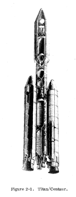
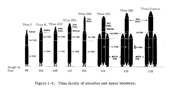
Before modeling the TITAN IIIE rocket, I made sure to look at some images and drawings of the rocket from NASA's archives. The key detail is that Voyager 1 was carried by what was the biggest TITAN series rocket, the TITAN III-Centaur otherwise referred to as TITAN IIIE. The vehicles consist of three stages: the Solid Rocket Motors (SRMs) which are the smaller rockets to the sides of the larger rocket, stage one which is the large central rocket, stage two which is the upper section of the rocket, and the Centaur stage which is the payload carrying stage.
Modeling TITAN IIIE - Stage 1 & 2
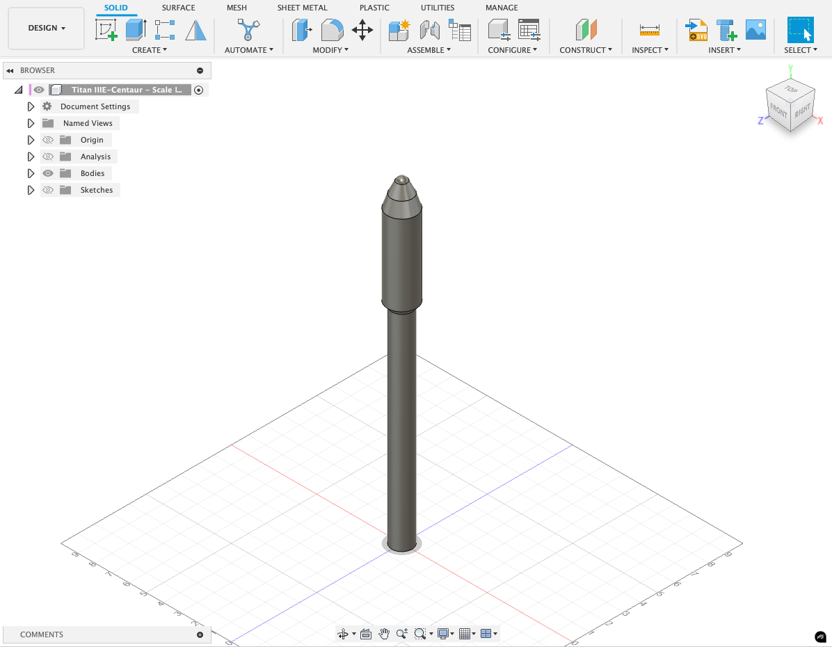
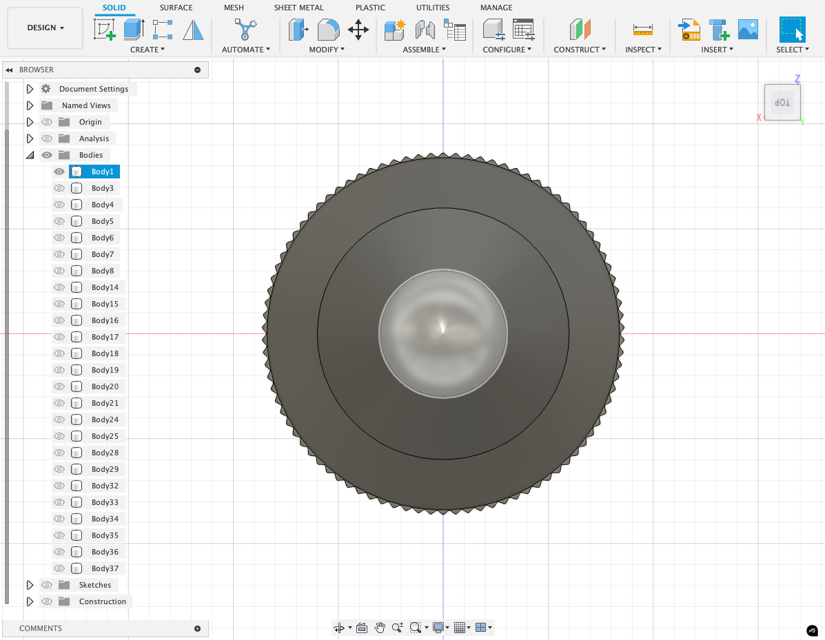


To model TITAN IIIE I opened up Fusion360 (F360) and started off by modeling the middle rocket, reffered to as Stage 1 & 2. To model the rocket, I started off by creating a sketch and outline the profile of the rocket, then revolving it to create the cylindrical shape. I then added the ridges on the stage 2 portion (upper) by creating a face perpendicular to the top of the rocket and using the circular pattern tool to create the ridge pattern, finally extruding it to create the ridges. The same process was followed to make the ridges just above the stage 1 portion (lower). Next, I extruded the mounting points for the connecting arms between Stage 1/2 and the SRMs, again using the circular pattern tool to copy the mounting points. After completing this step, I then used the profile of the Stage 1 rocket engine exhaust and revolved it to create the engine. Finally, I added the finishing touches on the Stage 1 rocket body — the “United States” and the solar panels.
Modeling TITAN IIIE - SRMs Boosters
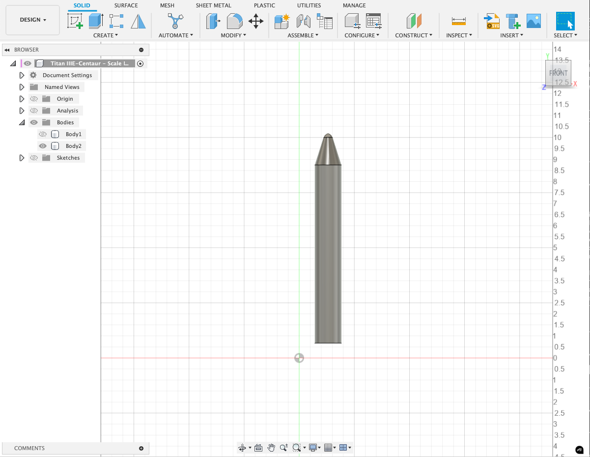


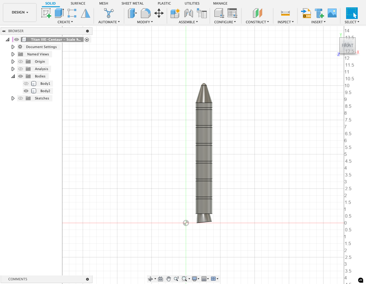
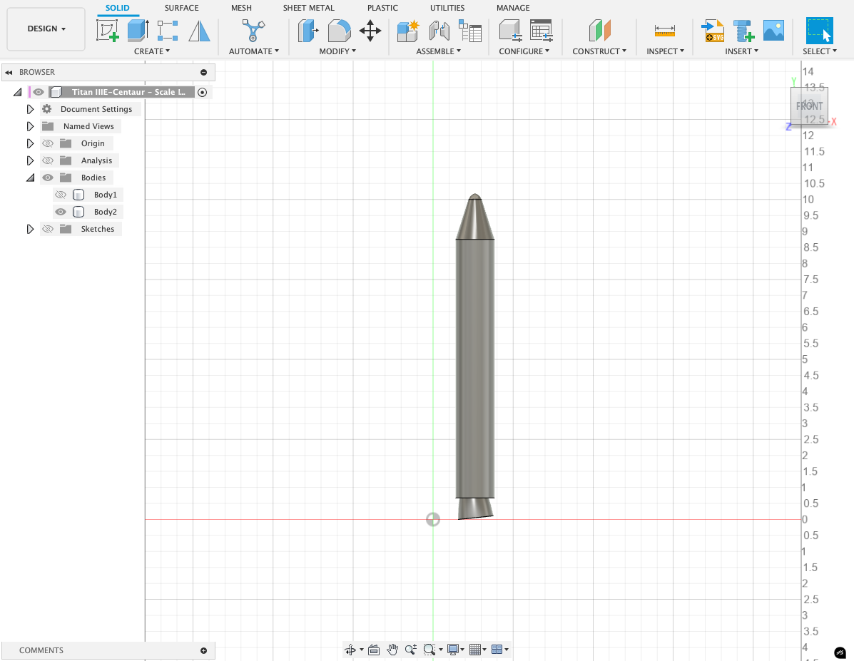

I started by modeling the right SRM, the one with the smaller tank -- the Thrust Vector Control Tank (TVC Tank) -- attached to it. To model the SRM I began with the same methodology as the Stage 1/2 rocket by outlining the profile of the main rocket and then revolving it around its center. After then creating the main model of the tank I created the mounting points for the connecting arms just like Stage 1/2. After making the connecting points, I then actually modeled the arms themselves, with the top arms being a simple bar, and the bottom arms being a triangular-shaped strut with two mounting points on the SRMs and one on the Stage 1/2 rocket. Then, I modeled the aft and forward staging rockets that would maneuver the SRM away from the Stage 1/2 rocket when being jettisoned from it. Then, I modeled the outer wiring and piping conduit situated on the outer edge of the SRM. At this point, I then mirrored the SRM to the other side since only the right side features the TVC Tank. Finally, I modeled the TVC Tank and its mounting arms and brackets to the SRM.
Modeling TITAN IIIE - Stage 2 (Stage 1 Detached)

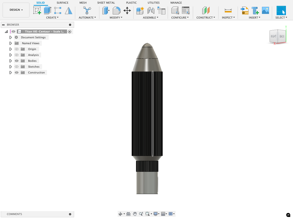

The final part of the TITAN IIIE rocket that I will model is the Stage 2 portion. To keep the modeling simple, I just copied and pasted the full Stage 1 part of the rocket and cut the bottom portion off. I then modeled the rocket engine itself at the bottom of the rocket. Additionally, I made sure to chamfer the bottom edge to represent the inner part of the shroud ring which can be seen above.
Final Result
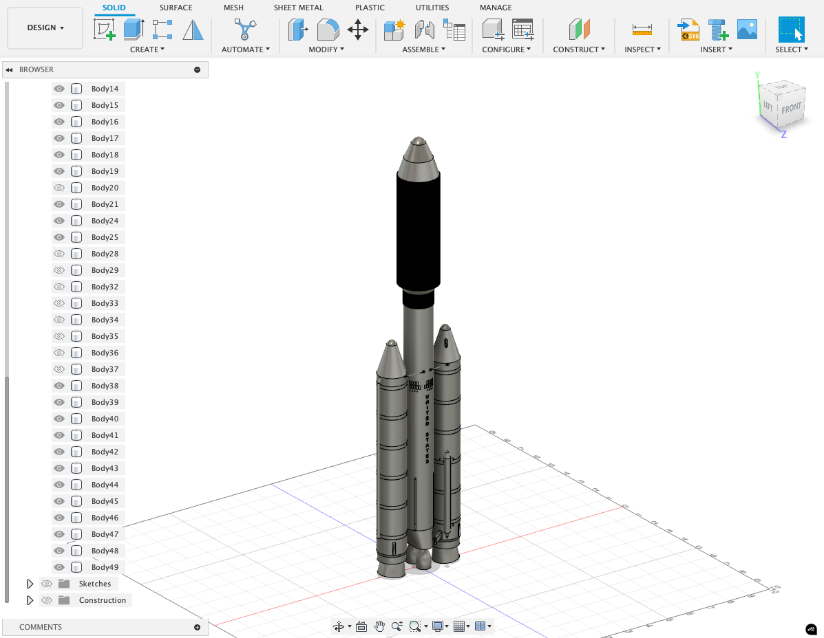
This is the completed TITAN IIIE model ready to be rendered.
Creating Scene 1


The next part of the project is actually rendering and animating it. I began with scene 1, the scene where the rocket actually takes off from the pad. First, I started by applying all the textures onto the rocket. These included the aluminum textures on the main body of the SRMS and Stage 1/2 of the rocket, the heat shields, the exhaust material, the solar materials on solar panels, and finally the orange retaining rings. After completing this step, I then used a fantastic blender plugin called Blosm which lets you import 3D Google Maps geometries and textures to create the Cape Canaveral launch complex where the TITAN rocket would launch from. Separately from the Google Maps textures, I made sure to add another layer for the water texture so that it would appear more realistic with more reflections. I then started to model the smoke and rocket fluids using the built-in simulations in Blender. This was by far the most time-consuming and difficult part of the whole animation. If you're ever considering doing fluids in Blender, I definitely recommend taking a look at THIS video, it goes through all the steps of setting up your domain and fluid and how to properly set up and bake your fluid simulation. With the help of this video, I completed the initial smoke plume and the rocket flames shooting out of the exhaust. I then used my custom smoke material above to create a more cartoon-esque texture that was simpler to render on the machine I had available while still looking somewhat realistic. I then imported the rocket launch pad into the scene. I ended off by adding a sun and keyframing all the objects, including the camera.
Creating Scene 2


Moving onto scene 2, this is the scene where the rocket is traveling through the atmosphere, and we can see the jettisoning of both SRMs. To make the render much simpler and less time-consuming, I went for a very minimalistic approach, only using a plane with a simple blue texture as the background and another plane with a cloud texture to act as the moving clouds in the atmosphere and to give the rocket the appearance of speed. To animate the scene, I inverted my thinking -- instead of having the rocket move throughout the scene, and having to have an enormous world, I instead thought of simply keyframing the clouds and just having to move the clouds. This turned out great in my opinion considering the enormous amount of extra time it would have taken to render out the alternative option. In terms of the flanes, I also copied the same domain from Scene 1 but I disabled the smoke texture since rockets don't actually produce smoke from their engines (they only produce smoke at launch because of the water that is pumped at the launch pad). Finally, I animated the falling SRMs using keyframes, not gravity since the rocket was at the origin and not moving.
Creating Scene 3


Naturally, after scene 2 comes scene 3. Personally, this was my absolute favorite scene, especially the way that I got the stage 2 rocket to appear out of the "abyss". The first thing I did for this scene was to create the Earth object. I used Blender Guru's amazing tutorial to make the Earth. The coolest thing that stood out to me is that the Earth textures all come from NASA and are real -- I find that so fascinating! Anyway, after following his tutorial, I then adjusted the Earth and camera so that I would start out the scene at the edge of daytime and both the camera and the Earth would spin opposite to each other so that the scene would slowly turn towards the light of the sun. This is how I created the "coming out of the abyss" effect for the Stage 2 rocket. Since, at this point, the Stage 2 rocket needs to be used I imported it. However, this time was easier because I only had to copy and paste the textures that I had already applied to the full rocket earlier. One more trick I learned while animating this scene was using the graph editor to change the way that the camera moved around to be smoother between keyframes. After comparing the non-edited graphs with the edited graphs, I was genuinely shocked at how I hadn't seen this before because the difference was night and day.
Creating Scene 4


Moving onto scene 4, in this scene I first introduced the Voyager 1 probe. This scene was probably the simplest scene to render in terms of time since the main thing to animate in the scene was just the camera pan. So, the first thing I did in the scene was import a NASA deep space HDRI which made the whole scene pop. I used the 8K HDRI so I could get a happy medium between render times and quality. Then, I imported the Voyager 1 Probe 3D model from NASA's 3D model repository, using their textures as well. All of these textures came out amazingly! I was really surprised at the amount of time and effort that NASA puts into giving the community these amazing resources, and now I've started to use them a lot more now that I'm aware of them. Apart from this, the other new thing I tried was making the camera automatically target the probe using a constraint, and this really helped in making the camera's motion in the scene much smoother since I didn't have to manually adjust the keyframes.
Creating Credit Scene


The final scene -- the credits scene! This was another really fun scene to make. My idea was to plot out Voyager 1's path up until the present day to show just how far it's traveled. To make this as accurate as possible, I used THIS amazing resource and website. Essentially, you plug in a date, and it tells you where planets were located on that specific date. So, using this website I was able to recreate exactly the motion of the planets since Voyager's launch. I just love how this tool and the other tools like from NASA allow anyone to go on their computer and make these realistic and accurate animations/simulations relatively easily. After keyframing the planets, I then created the path of Voyager 1 and constrained Voyager 1 to the path for the duration of the animation with the camera also constrained onto Voyager 1. As a finishing touch, I then made a red ring around the probe so it's easier to see the path it takes during the animation.
Final Result

Andddd that's it!! After going through and painstakingly rendering all the animations, I then edited them and combined them on DaVinci Resolve 19 to form the short film. So, let's take a look at the results!
Final Remarks

Creating this video has been an incredibly fulfilling experience for me, especially since it’s my first-ever rendering project. While I faced setbacks, such as the limitations of using a low-quality Earth texture due to the library computer and accidentally setting an early keyframe that made the space HDRI appear frozen in Scene 4, I’m proud of what I managed to achieve. Although I couldn’t make the animation as long as I wanted due to time constraints at the library, I loved how the beat of the song perfectly synced with the video. The effect of the Stage 2 rocket appearing out of the dark turned out to be one of my favorite moments. I also feel that using a niche song like “GO!” by Public Service Broadcasting added a unique touch, making this project feel distinctively personal.
I want to extend a heartfelt thanks to my local library for letting me use their computer for two weeks. Without their generosity, I wouldn’t have had access to the tools I needed to explore rendering for the first time. Despite the challenges, this project taught me so much about animation, timing, and creativity. The process has left me eager to improve and continue working on future projects, taking these lessons and making something even better next time.