Water Rocket - Electronic Systems Design
by luisferniño in Circuits > Arduino
12525 Views, 170 Favorites, 0 Comments
Water Rocket - Electronic Systems Design
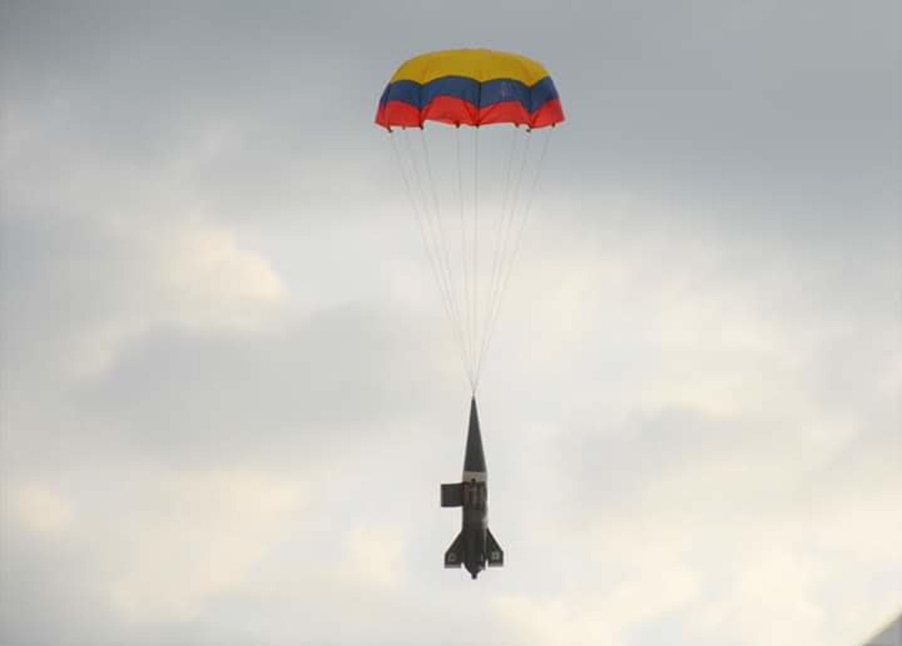


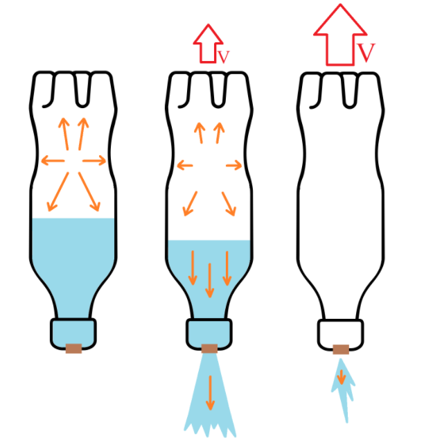
In this instructable, we are gonna build a Water Rocket with an automatic parachute ejection mechanism, and a data transmission system so we can monitor the rocket's orientation (estimated from accelerometer and gyroscope data) while it's on the air.
A water rocket is a model rocket that uses water and compressed air inside a pressure chamber (usually a PET bottle) as a thrust motor. The operation of the rocket can be explained by Newton's third law, where the water in the compression chamber is thrown out by the compressed air as it tries to release its pressure releasing the accumulated potential energy, causing a force to be generated in the opposite direction that propels the rocket.
Supplies
Rocket airframe
- 3x PET Bottles 3L size (*It’s important that at least one of the bottles was used to store soda because it has to be able to withstand high pressures)
- 4x Balsa wooden boards 200*25mm
- 8x Screw
- 1x Spray paint
- 1x Rubber band
- 1x Parachute (We used an old umbrella, attaching rope to each tip of the cloth)
- 1x Corrugated plastic board 250*250mm (Also known as Correx or Corriflute)
Electronics
- 4x Zip Ties
- Cardboard
- 1x Perfboard (Also known as solder-able breadboard)
- 1x Accelerometer (We used an MPU6050, it has an accelerometer and gyroscope)
- 2x Arduino board (We used an Arduino nano and an Arduino mega)
- 1x 3.3 V Voltage regulator (We used the LM317 adjustable voltage regulator)
- For the Voltage regulator circuit using an LM317
- 1x Resistor (390 Ohm)
- 1x Resistor (240 Ohm)
- For the Voltage regulator circuit using an LM317
- 1x Servomotor (We used a generic SG90)
- 2x NRF24L01+ module
- 1x Battery to supply power to the electronics board (We used a Power Bank)
- To connect the Power Bank to the electronics board.
- 1x USB male type A connector
- To connect the Power Bank to the electronics board.
- Female & Male headers
- Tape
- Double-sided tape
- Cables & Wires
- Hot glue
Tools
- Hot glue gun
- Cutter
- Scissors
- Marker
- Soldering iron
- Tweezers
- Measuring tape
- Stapler
- Water Rocket Launcher (We don't explain in this instructable how to make the rocket launcher, but you can check out this amazing article by air command water rockets to build one yourself)
Parachute

Measure the radius of the bottle
For this measure the circumference as seen in (1), then apply the equation r = c / (2*pi) (where c is the circumference) to find the radius, in our case the radius was 60 mm
With this information mark 2 circles with the radius of the bottle minus 1 mm (in or case that was 59 mm) on a cardboard and cut them, as shown in (2) and (3).
For each circle, make the lines as shown in (4)
For this, we first make a line that goes through the center of the circle, this line will be called line 1
Measure 40 mm on one end of line 1 and draw a perpendicular line that touches the borders of the circle, this line will be called line 2
Measure 20 mm on the other end of line 1 and draw a point
Now draw a line between the point and each end of line 2
Measure one of the recently drawn lines, this value will be called L

Taking the above measurement (L), draw on the cardboard a rectangle 110 mm high, and (L) x 4 mm wide, mark a vertical line every (L) mm (5)
Cut the large rectangle and cut the line at the middle resulting in 2 rectangles of equal size as shown in (6)
For each of the rectangles, cut the top layer of the cardboard through the marked line so we can fold them
Put hot glue on the lines marked on one of the circles and glue one of the folded rectangles, then glue the other rectangle behind the previous one to reinforce it.
We need holes for the zip tipes, so mark a line approximately 15 mm from each end of the rectangle, and draw 4 rectangles attached to that line approximately 3 mm high by 5 mm wide that are approximately equal distances apart as shown in (9)
Glue the other circle on top
Cut the small rectangles and verify that the zip ties fit through the recently made holes.

For the parachute ejection system cavity at the top of the rocket mark a circle approximately 50mm from the bottom of the bottle as shown in (11) and cut through it, the of this is a bottle without the bottom part.
Put the electronics support made in cardboard inside this bottle.
With the support inside, mark a rectangle on the bottle, covering the front of the support (the front of the support is the side where we drew the holes for the zip ties, or the side where there's the most space), the rectangle should have 20 mm extra at each horizontal end.
Now remove the cardboard support and cut the rectangle with a cutter as shown in (12), (13) and (14), careful with cutting the rectangle out of the bottle, as this part will be used later to hold the parachute inside
Then make a hole in one of the short ends of the rectangle and put a rubber band thorugh it as shown in (15), finally attach the rectangle with tape on the right side of the hole (that's while holding the bottle upright), so that half is unattached thus acting as a lid in the hole as shown in (16).

Looking at the cardboard support from the back, on the right side mark a rectangle approximately in the center with the dimensions of the bottom of the servomotor, for the one we used (SG90) the dimensions are 22 mm high by 12 mm wide as shown in (18)
Now cut the rectangle and insert the servomotor putting first the cable
Secure the servomotor to the bracket with the screws* or hot glue as shown in (19) and (20)
*The screws might not work if the cardboard is a little weak, applying too much force to the screws can also result in a loose mount, in that case, hot glue is easier and more secure
On the left side of the cardboard support, make a small hole to pass the servo cable through, put it as close to the right as possible as shown in (19)


We are gonna make the parachute spring and attach it to the cardboard support
From one of the unused bottles, cut a 230 mm x 96 mm rectangle (measure it with measuring tape) for the parachute spring as shown in (21).
At each short end of the recently cut rectangle, mark a line approximately 10 mm from the border, align the marked line with the edges of the holes at the ends of the cardboard support (on the back of the cardboard support), and put a mark over each hole as shown in (22).
Make a hole on each of the marked rectangles with a cutter or a soldering iron.
Use zip ties to secure the spring to the cardboard support as shown in (23) use pliers if necessary to pass the zip ties through as shown in (24) (you may also bend the spring if it's getting in the way).
Insert the cardboard into the bottle so that the spring is on the side of the hole
To push the cardboard support in, it might be necessary to first push the spring on the support, and then push the support inside the bottle
Draw a rectangle on top of the servomotor and cut it out, this hole is where the rubber band will pass to be attached to the servomotor keeping the lid closed and the parachute compressed against the spring.
In the video you can see how to put the parachute inside the rocket.
Electronics


The electronics is mainly composed of an Arduino Nano, an MPU6090 Accelerometer+Gyroscope, an LM317 voltage regulator circuit set to 3.3V, a Power Bank, a radio module NRF240L01+ and a servomotor, the following schematic (rocket.pdf) shows the connection diagram.
We put some female headers on the board for the radio module, and connected it using long male to female cables
For the servomotor, we put some male headers
The voltage regulator is used to provide power to the NRF24L01+, as we found that the 3.3V output of the arduino was not providing enough power and the program would fail sometimes
You may connect the components using any method you want, but keep in mind the space inside the cardboard support is limited.
To mount the electronics board to the cardboard support, first, take it out of the bottle (1), place the electronics on top of the left side of the cardboard support and mark the upper left and the lower right corners as shown in (2). Remove the board, and in each corner mark and cut 2 small rectangles approximately 10 mm apart as shown in (3).
For each pair of holes, pass a small wire through the holes from the back of the cardboard support (might be necessary to push the spring to get the wires through) and with wires secure the perfboard to the cardboard as shown (4).
On the last picture, we show the result of attaching one of the corners, one end of the wire goes through a hole on the board, and then we twist it so it stays in place.
Downloads

On the top of the board, mark and cut a rectangle approximately 10 * 30 mm on the cardboard support as shown in (5). Pass the power and radio module (NRF24L01+) cables through the hole.
Then connect the power cable to the Power Bank, and the NRF24L01+ to the board as shown in (6) and (7). Finally secure the elements to the cardboard (8).
We used tape to hold the radio module in place, and double sided tape to hold the Power Bank in place, also reinforced with tape
Keep in mind that for the cardboard support to fit inside the bottle, the elements on top of it should not cross the border of the circles, so keep everything inside the circle.
Before putting the cardboard support in the bottle, upload the program (rocket.ino) to the arduino and check the operation of the program using the following testing procedure.
Note that we need multiple libraries installed, these can be easily installed on the arduino IDE using the library manager, these are the libraries
RF24 by TMRh20, Avamander
MPU6050 by Electronic Cats
Testing procedure
Drop the cardboard support from a small position on a smooth surface, and see if the servomotor changes its position, after this restart the arduino and redo the experiment several times to be sure that the servomotor is going to move everytime since this is the one that will deploy the parachute.
If the servomotor does not move, increase the threshold value in rocket.ino [ #define THRESHOLD 1000 ] to a value of 1500, and test again, if necessary you can increase it further.
If the servomotor changes position when the cardboard support is not being dropped, decrease the threshold value in rocket.ino [ #define THRESHOLD 1000 ] to a value of 500, and test if it works correctly when dropped.
The servomotor must start in vertical position, and when dropped the support must move clockwise to the horizontal position as shown in (9), if not it is necessary to set the start and end angle
For that, upload the program test.ino, and through the arduino serial monitor (set to 115200 bauds), write a number between 0 and 180 so the servomotor stays in a vertical position, when a value is found, update in rocket.ino the value [ #define START_ANGLE 110 ]
Then, enter a value, that makes the servomotor move from the vertical position clockwise to the horizontal position, when a value is found, update in rocket.ino the value [ #define END_ANGLE 30 ].
Note that if it's not possible to find appropiate values, you may need to reposition the servo arm.
Finally, after testing, insert the cardboard support into the bottle, the result is shown in (10).
You may be wondering how are we going to turn on the electronics when they are inside the bottle, for that, on one of the next steps we will be making a hole to connect/disconnect the power cable at will
Electronics (Station)

Now make the station, this one just requires an arduino board and radio module, the station receives the data from the rocket and sends it to the computer so that we can use it.
The connections are simple so we won't need an schematic
Connections:
Arduino Board | NRF24L01+
Pin 7         | CE
Pin 8         | CSN
3.3V          | V+
GND           | GND
// For the following pins check a pinout of your board
SCK           | SCK
MISO          | MISO
MOSI          | MOSI
After making the connections, upload the program station.ino to the board
Note that we need a library installed, it can be easily installed on the arduino IDE using the library manager, the library is RF24 by TMRh20, Avamander
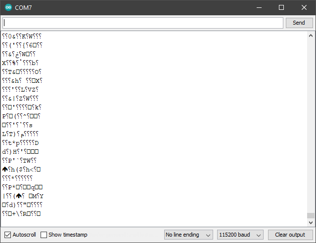
To test if we can receive data, take the cardboard support out of the bottle temporarily so we can turn it on by connecting the power cable to the Power Bank, with the rocket electronics turned on, and the station connected to the computer, open the serial monitor on the arduino IDE at 115200 bauds, if data is being received, you will see random characters appear while the rocket electronics are turned on (as shown in the second image).
If we are not receiving data, check if there are any errors printed on the serial monitor with the station, if not, connect the arduino board on the rocket electronics to the computer and check the serial monitor (at 115200 bauds) to see if there are any errors printed. If there are connection errors with the radio module or the accelerometer, check the connections on the board.
Downloads
Airframe

For the construction of the fins cut 4 pieces of 25mm x 200mm balsa wood boards as seen in (1) and (2), to create the shape of the fin cut four pieces of corrugated plastic with the measures seen in (3) and (4), and finally with the help of screws join the two parts (5).

Each of the flaps should be positioned at 90° of each other and secured with tape to the plastic bottle (8).

In the position of the Power Bank, where the connection is located, make a hole so we can disconnect and connect the power bank as shown in (9) and then cover the hole with tape not to affect the aerodynamics of the rocket as shown in (10) (the tape is highlighted in blue).
Tie the parachute rope under the bottle cap, make 2 or more knots as shown in (11) and (12)
To assemble the rocket put the bottom of the bottle with the fins inside the bottom of the bottle with the electronics (13), to keep it in place add 4 pieces of tape at 4 different points at equal distances of each other, it is important that the two bottles are straight, finally add more tape around the joint as illustrated in (14).
Now we have most of the the rocket done, as shown in (15).

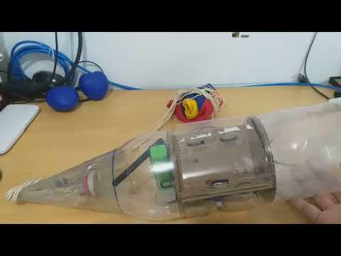
For the rocket nosecone, take a sheet of acetate or a thin sheet of plastic, and mark 2 perpendicular lines of 180 mm as shown in (16).
Draw an arc between the 2 ends of the lines.
On one of the 2 lines draw a rectangle 20 mm wide and cut out the resulting shape (17).
Cut out the corner of the rectangle where the 2 perpendicular lines meet as shown in (18).
Roll the shape into a cone shape and cut off the tip as shown in (19).
Wrap it around the parachute rope and staple the cone through the rectangle as shown in (20), reinforce the cone tip joint with tape (21). finally tape the cone to the bottle taking care that it is straight (22), use as much tape as neccesary.
We have finished our rocket! as shown in (23)
Now you can paint it if you wish, this is completely optional but recommended!
On the video, you can see the general procedure before launching, which is turning on the electronics, checking that the servomotor is in the correct position, putting the folded parachute inside the rocket, and closing the rocket's lid by putting the rubberband on the servo's arm.
We also simulate a free fall to see how the parachute ejects
Visualize Data

To visualize the data received by the station we use a processing sketch as shown in the video.
We need to Download Processing 3
Download all the attached .pde files and put them inside a folder named rocket, then open rocket.pde
Before running the sketch we need to change line 9 [ String serialPort = "COM7"; ] update the serial port to the one of your arduino board
We also need to install a library, this is done using the contribution manager on processing (Sketch > Import Library > Add Library)
the library to install is ToxicLibs by Karsten Schmidt
Run the sketch
You should see the graphs respond when you move the rocket, and a rectangular prism following (or at least trying to follow) the orientation of the rocket.
The file data.csv is some example data in form of a table, it can be opened with Excel to make plots, it has 6 columns in total, the first 3 are the components of the acceleration in Gs, and the other 3 are the angular velocity for each axis in degrees per second (The data was taken by applying some rotations and movement to the rocket by hand just like in the video)
Launch!
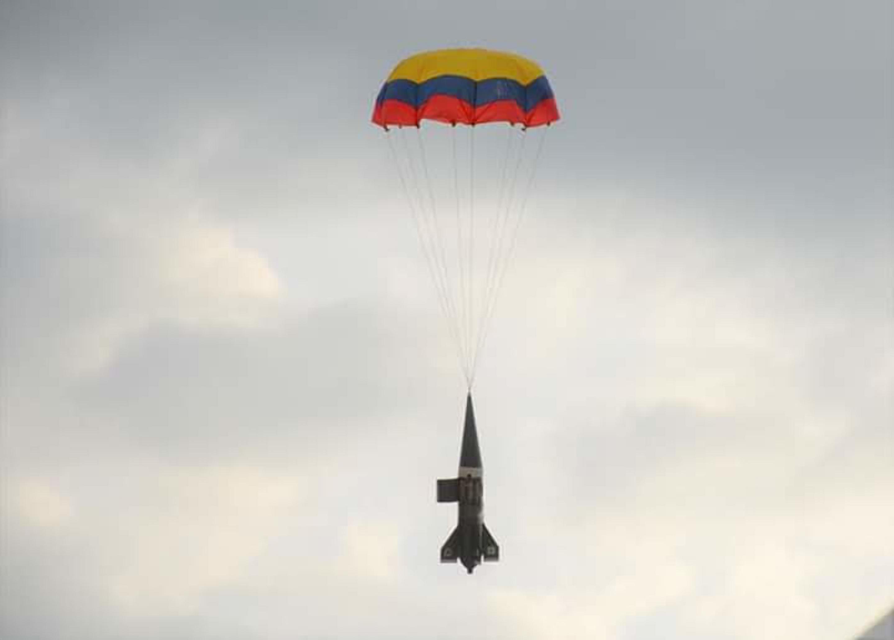
Finally, do the general procedure before launching for the electronics, fill the rocket with about 1/3 of water, put your rocket on a water rocket launcher, pump air into it and fly away!, the rocket should automatically deploy the parachute when falling, and the estimated orientation of the rocket can be visualized in the processing sketch.