Water Softener Salt Meter Using a Bathroom Scale
by omanavekar in Circuits > Sensors
850 Views, 6 Favorites, 0 Comments
Water Softener Salt Meter Using a Bathroom Scale

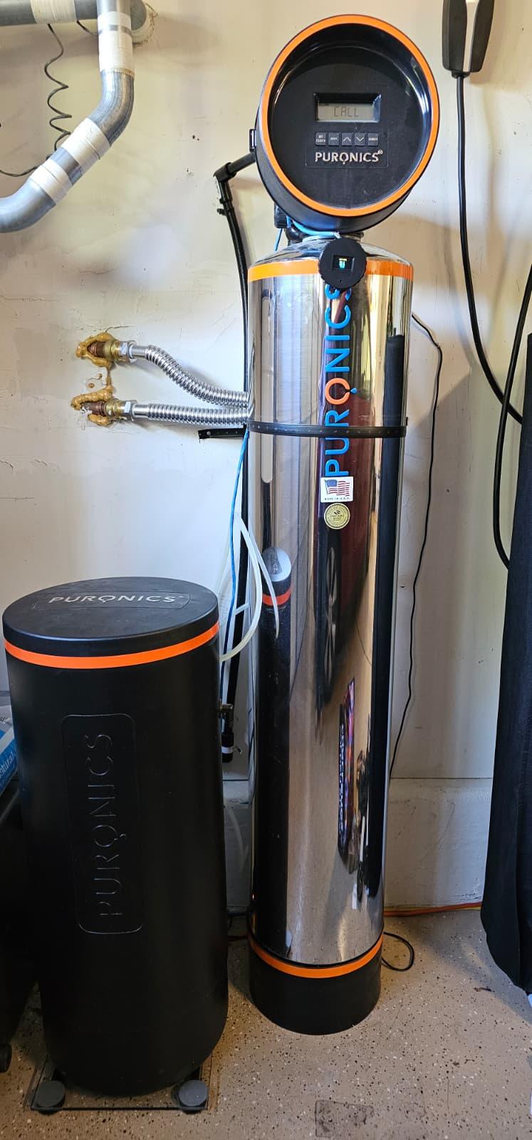
If you have a water softener at home, you know how important it is to keep the brine tank filled with salt. The problem? It’s easy to forget to check. More than once, I’ve gone weeks with an empty tank, which means hard water creeping back into the plumbing, spots on dishes, and extra wear on appliances.
To solve this, I built a simple monitor that shows me exactly how much salt is left. The "repair" is straightforward: take an old bathroom scale, connect its load cells to an HX711 amplifier, and use an ESP32 microcontroller with a small display to show the tank’s weight. When the salt gets low, a buzzer reminds me to refill.
Since it runs on an ESP32, it can be upgraded with wireless capabilities in the future!
Supplies
Electronics:
- Standard bathroom scale (I got one for $3 at a thrift store)
- ESP32
- HX711 amplifier
- SSD1306 0.96" OLED
- Digital light dependent resistor module (preferably with a LM393 op amp)
- Buzzer
- Pushbutton switch
- DC barrel jack (optional, makes connecting the scale to the power supply easier
- 6-wire cable (I found using an ethernet cable works great!)
- 2 30mm M4 Bolts
- Small screws (for mounting electronics)
- Misc wire/connectors (JST male/female connectors will come in handy if you have them!)
- 15mm wide coin-type magnet (for mounting to wall/resin tank)
- 5V Power source/wall wart.
Tools:
- Soldering iron and solder
- Multimeter
- 3D Printer
- Hot glue or epoxy
- Screwdriver
- Pliers
- Wire cutters
Project Architecture
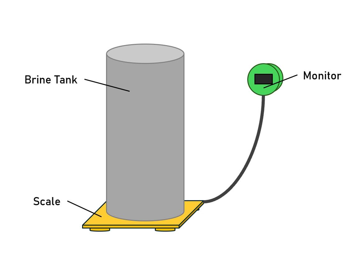
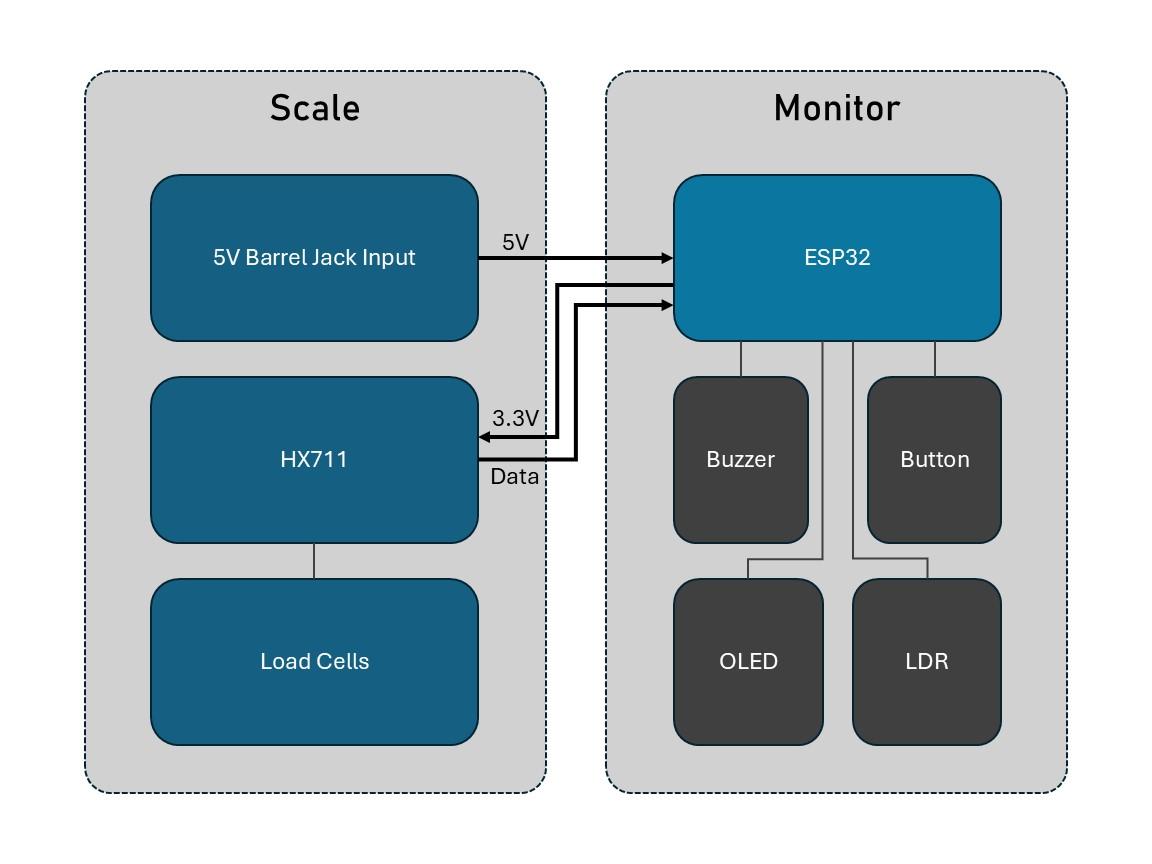
Before we get started let's go over the components of the system and my design decisions. The setup has two components: Scale and Monitor
Scale: This part sits under the softener's brine tank and periodically weighs the salt present. I chose to use a bathroom scale because it is cheap, rugged, and non-intrusive to the softener tanks. The power input will be built into the scale as it is low to the ground (avoids long power wires going into the monitor). The HX711 amplifier will be placed inside this to prevent sensitive analog signals traveling long cable runs.
Monitor: This part contains the ESP32 processor, OLED display and peripheral components. It will be magnetically attached to the resin tank or mounted to a wall. It gets power and HX711 data from the scale via a cable harness. On top of displaying the weight, it contains a button to recalibrate the system, a buzzer to warn people when salt is low, and a LDR to turn off the display at night/low-light conditions.
Disassemble the Scale
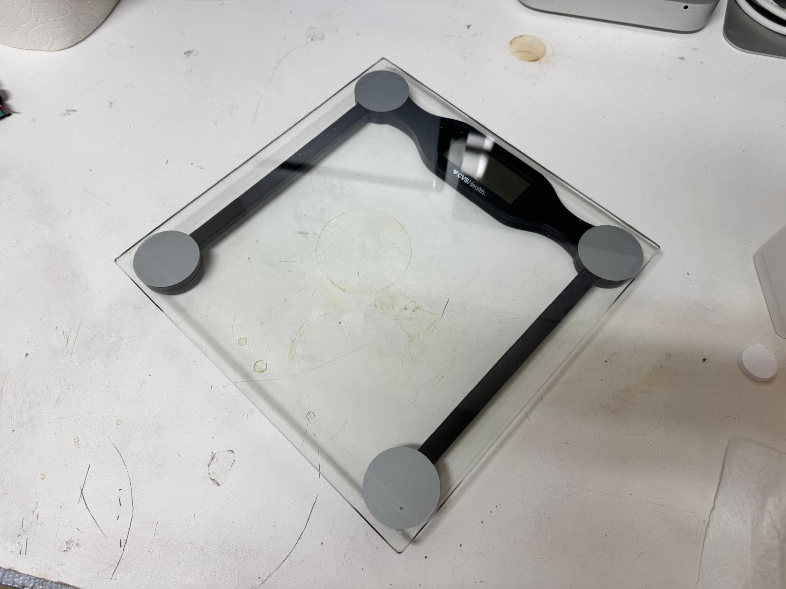
Note: Most digital bathroom scales use four 3-wire load cells (each with a red, black, and white wire). These are half-bridge sensors, and together they form a full Wheatstone bridge. If your scale has a different setup (like 4-wire cells or a single pre-wired module), your wiring will be different.
- Open the scale
- Remove the batteries.
- Flip the scale over, take out all screws (check under rubber feet/stickers), and carefully separate the housing.
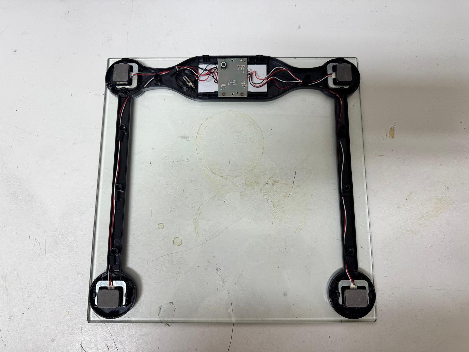
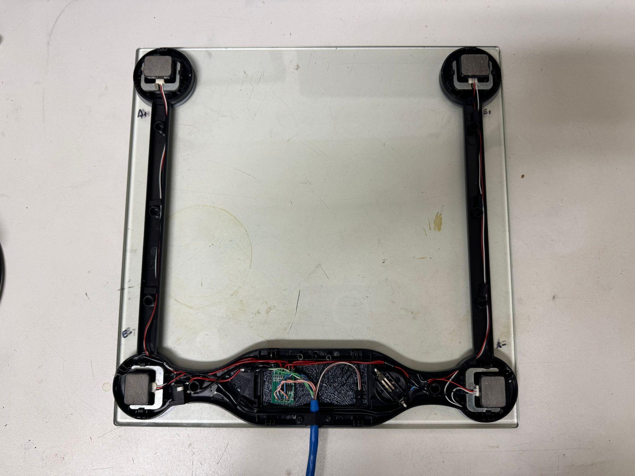
- Locate the load cells
- You should see four small aluminum bars, one at each corner, with three wires coming out of each (usually red, black, white).
- These are the only parts of the original electronics we need.
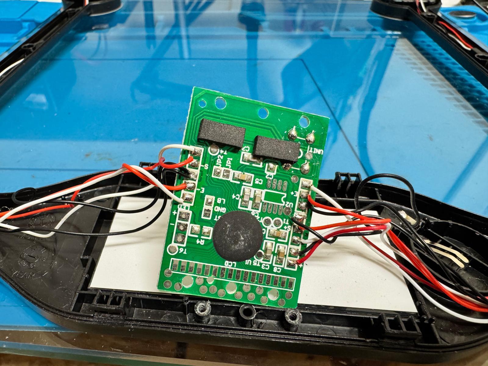
- Remove the stock electronics
- Find the main PCB that the twelve load-cell wires connect to.
- Cut or desolder the load-cell wires from the board.
- The LCD, buttons, and PCB can all be set aside for recycling.
- Label the load cells
- Mark each corner (e.g., FL, FR, RL, RR).
- This will make it easier to wire them into a full bridge in Step 2.
- Free and tidy the wiring
- Keep the wires as long as possible when cutting them away from the old PCB.
- Gather them into a single bundle and add a small knot or zip tie inside the base for strain relief.
At this point you should have:
- A bare bathroom scale frame with four 3-wire load cells still mounted.
- Twelve loose wires (3 from each corner), ready to be wired to the HX711 amplifier in the next step.
Wire the Sensors to the HX711
The HX711 is a tiny, inexpensive amplifier designed specifically for load cells. The voltage signals from the sensors are extremely small (millivolts), so the HX711 boosts and digitizes them so the ESP32 can read reliable weight values.
We’ll mount the HX711 inside the scale’s enclosure, close to the load cells, so the sensitive analog wiring is short and less noisy.
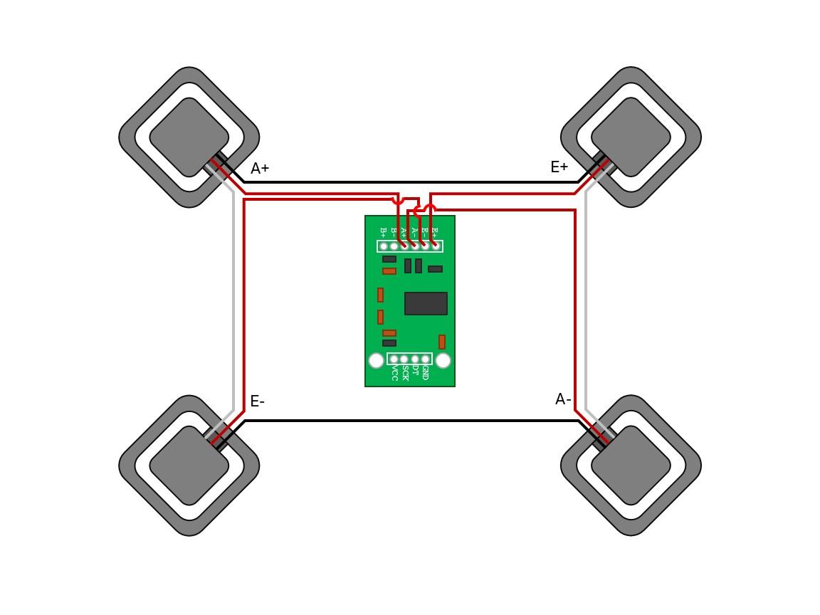
- Understand the load cell wires
- Each corner sensor only produces half of the signal, so we’ll wire them in pairs.
- Pair the sensors
- Opposite corners are paired together (e.g., front left + rear right, front right + rear left).
- This balances the bridge so the scale responds evenly no matter where weight is applied.
- Connect to HX711 (schematic provided)
- Double-check with your schematic before soldering.
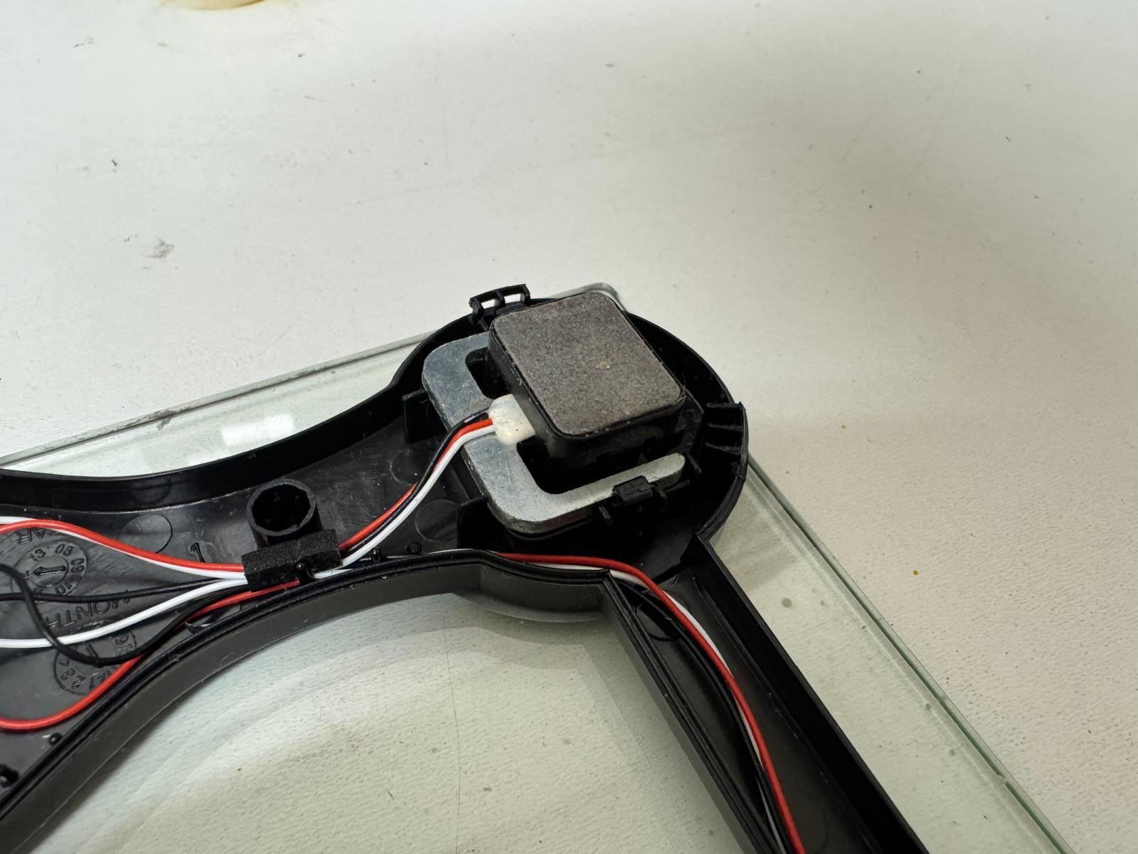
- Mount the HX711 inside the scale
- Solder the load-cell wires to the HX711 pads.
- Use double-sided tape or hot glue to secure the HX711 board to the inside of the scale’s base so it doesn’t rattle around.
Create a Harness Between the Scale and Monitor
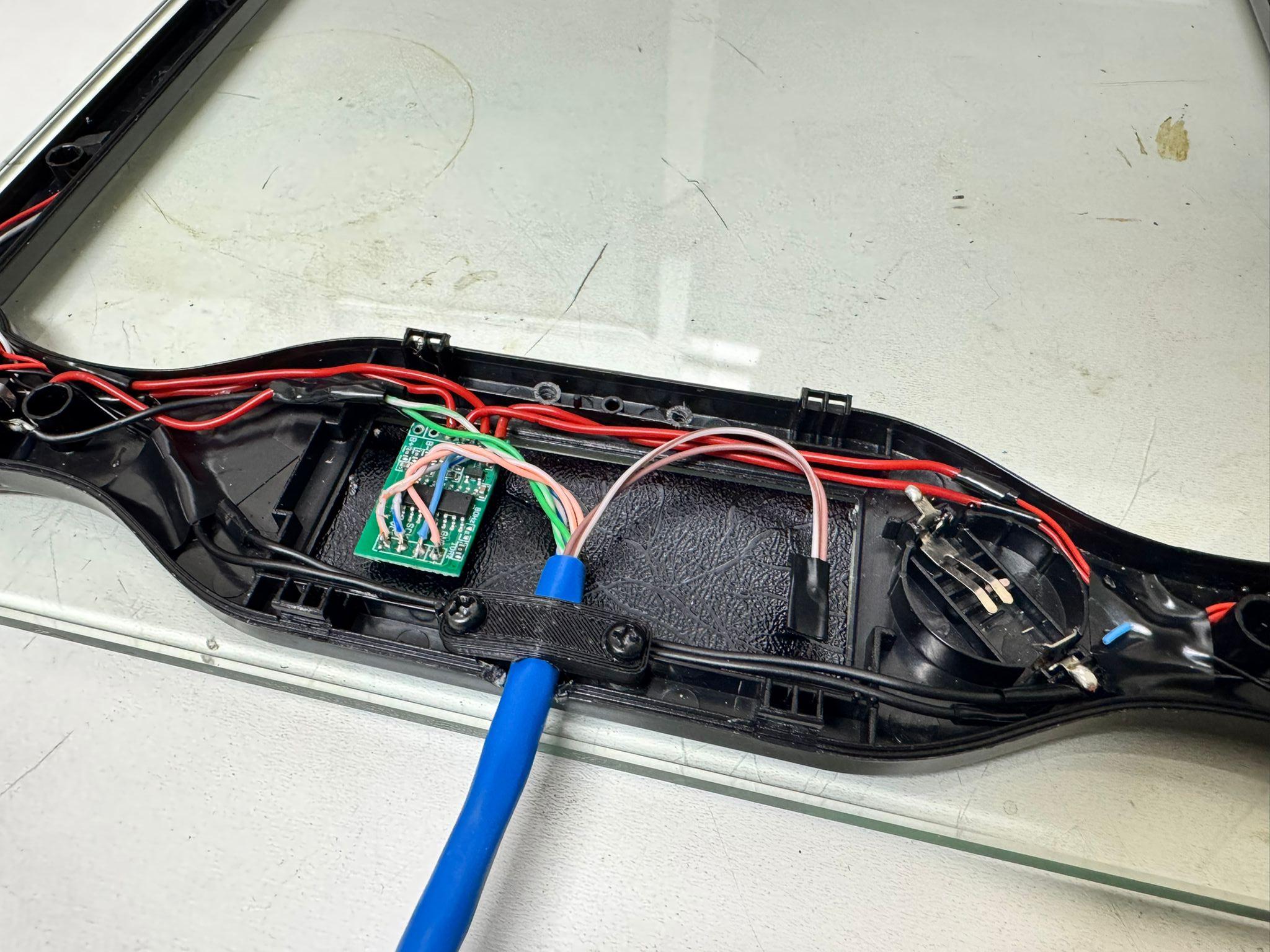
Now that the HX711 is mounted inside the scale and wired to the load cells, the next job is to connect it to the monitor. We’ll use an Ethernet cable as a durable, tidy harness to carry both power and data between the two enclosures.
To keep things simple, the DC barrel jack is mounted on the scale enclosure. Power enters the scale first, then travels up the Ethernet cable to the ESP32, and finally the ESP32 sends regulated 3.3V back down to power the HX711. This prevents messy power cables going up to the monitor.
- Mount the barrel jack on the scale
- Drill a hole in the side of the scale base and mount the DC barrel jack.
- This will be the single external power input for the whole system.
- Break out wires from the jack if needed.
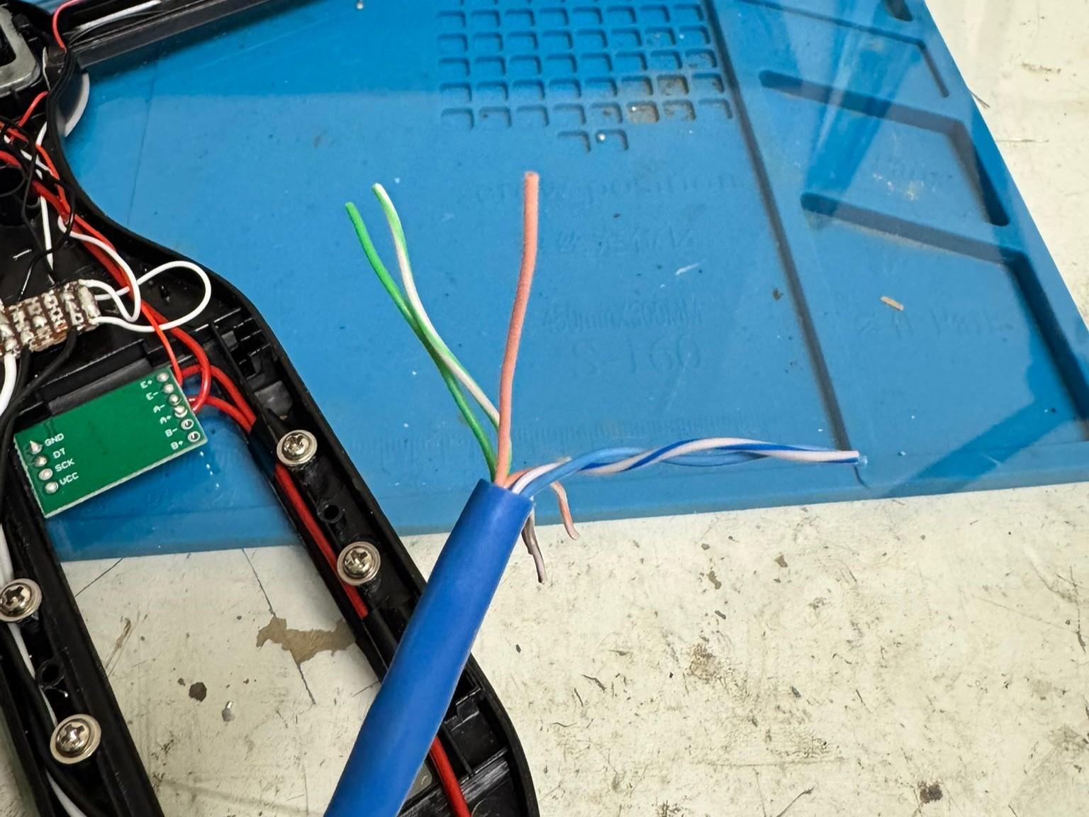
- Prepare the Ethernet cable
- Cut to length (this depends on how far the scale will be from the monitor, for my case 6 feet was plenty).
- Strip the sleeves both ends expose 3-4". For clarity I have included my color assignments (all ethernet cables have the same color scheme).
- Mount the sleeve of the ethernet cable to the scale enclosure to prevent strain on the internal wires.
- Assign and solder the Ethernet wires
- Green/White: 5V (barrel jack 5V)
- Green: GND (barrel jack GND)
- Orange/White: 3.3V (HX711 VCC)
- Orange: GND (HX711 GND)
- Blue/White: Clock (HX711 SCK)
- Blue: Data (HX711 DT)
- Brown/White: Unused
- Brown: Unused
Important: The HX711 must run on 3.3V, so it’s powered from the ESP32 regulator, not directly from the 5V barrel jack. As a sanity check, use a multimeter to test continuity for each wire.
After this step you should have:
- A barrel jack on the scale enclosure for power input.
- An Ethernet cable carrying both power and HX711 data lines.
- The ESP32 now feeds regulated 3.3V back down to power the HX711.
Now that the scale electronics are complete, reattach the scale's enclosure to prevent damage to the sensors/amplifier.
Print the Monitor Enclosure
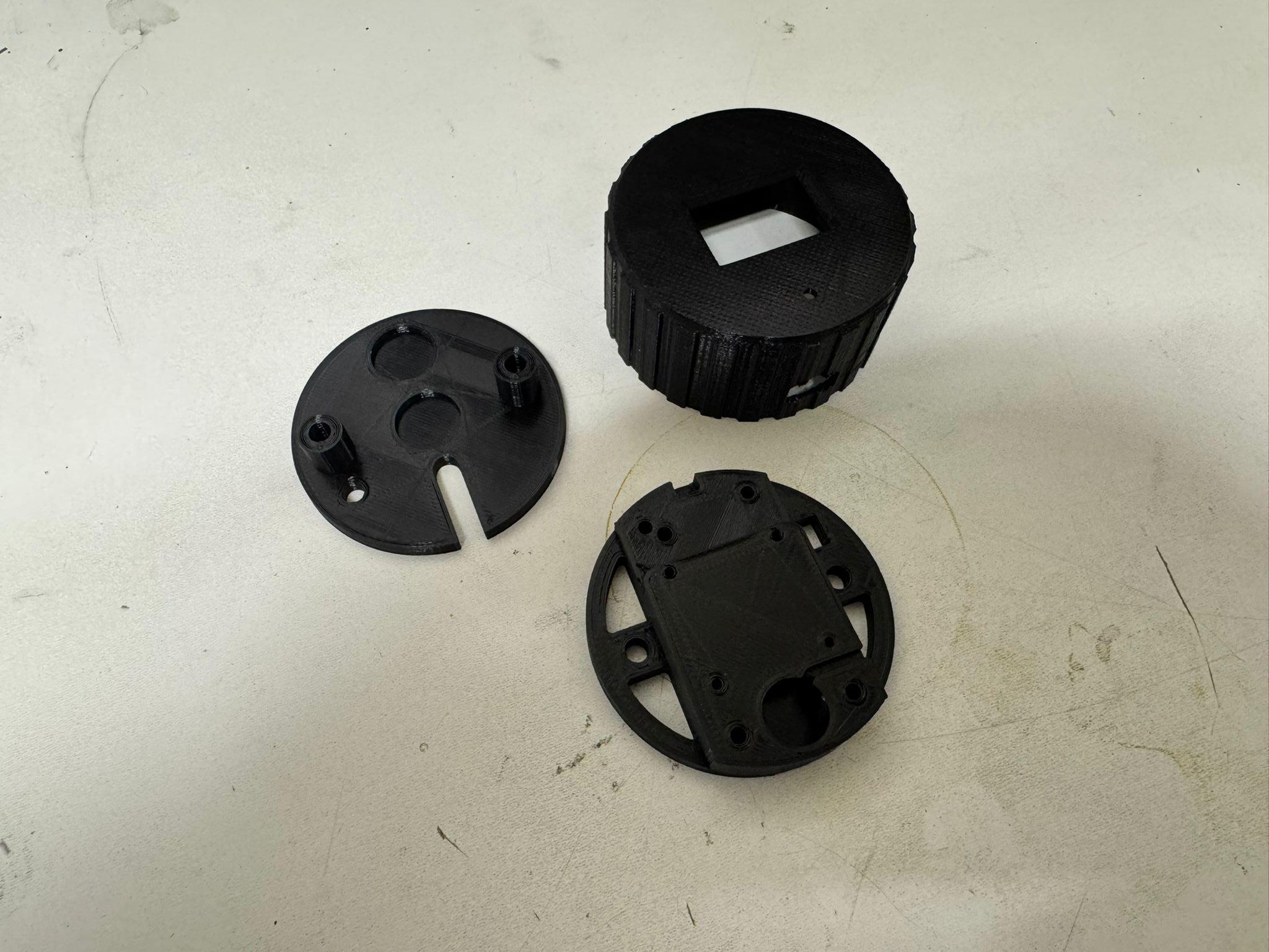
With the scale wired up and the Ethernet cable carrying both power and data lines, the next step is to build the monitor unit. This is where the ESP32, OLED display, and buzzer live. This module not only shows the salt level locally but also provides room for future wireless upgrades like Telegram alerts.
Print the attached STL files. We will use the electronics mount part in the next step.
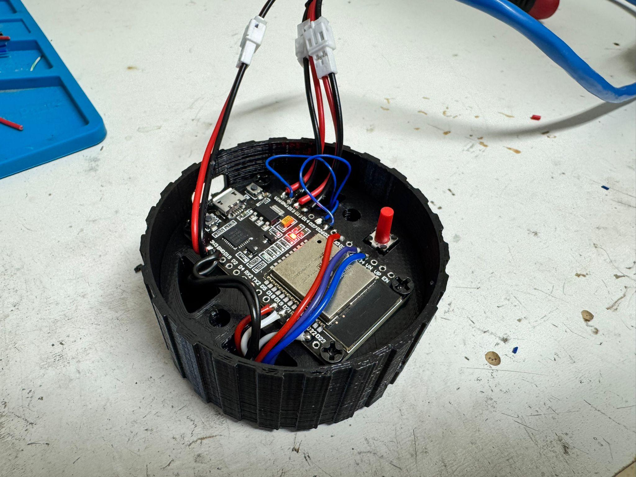
Assemble the Monitor Electronics
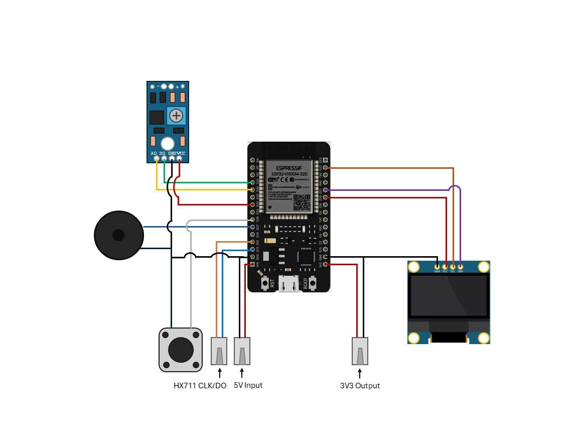
This step is the most complex. Make sure the follow the attached schematic and check for continuity when needed. The easiest way to do this is to run breakout wires from each module before mounting. Then, each module can be mounted and their connections soldered to the ESP32. Below are the connections for each module:
- OLED:
- VCC → GPIO19
- GND → GND
- SDA → GPIO21 (default I²C pin)
- SCL → GPIO22 (default I²C pin)
- Buzzer:
- + → GPIO27
- - → GND
- Button:
- + → GPIO26
- - → GND
- LDR Module (breakout the actual sensor and mount on the top as shown):
- VCC → GPIO33
- GND → GND
- AO→ GPIO35 (optional, not used)
- DO→ GPIO34
Once done you should have:
- A partially assembled monitor.
- ESP connected to the buzzer, button, OLED and LDR module.
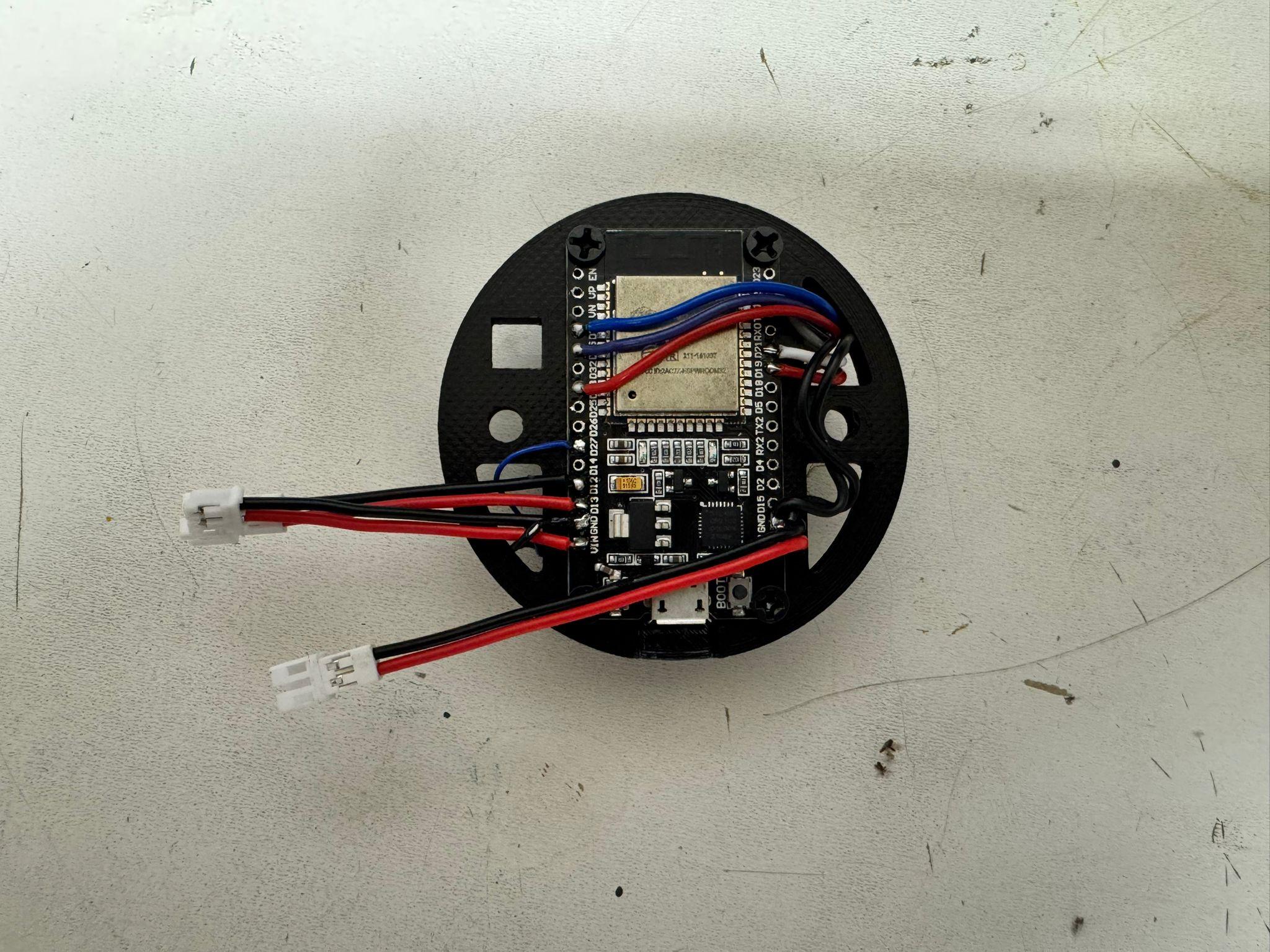
Wire Scale Harness to Monitor
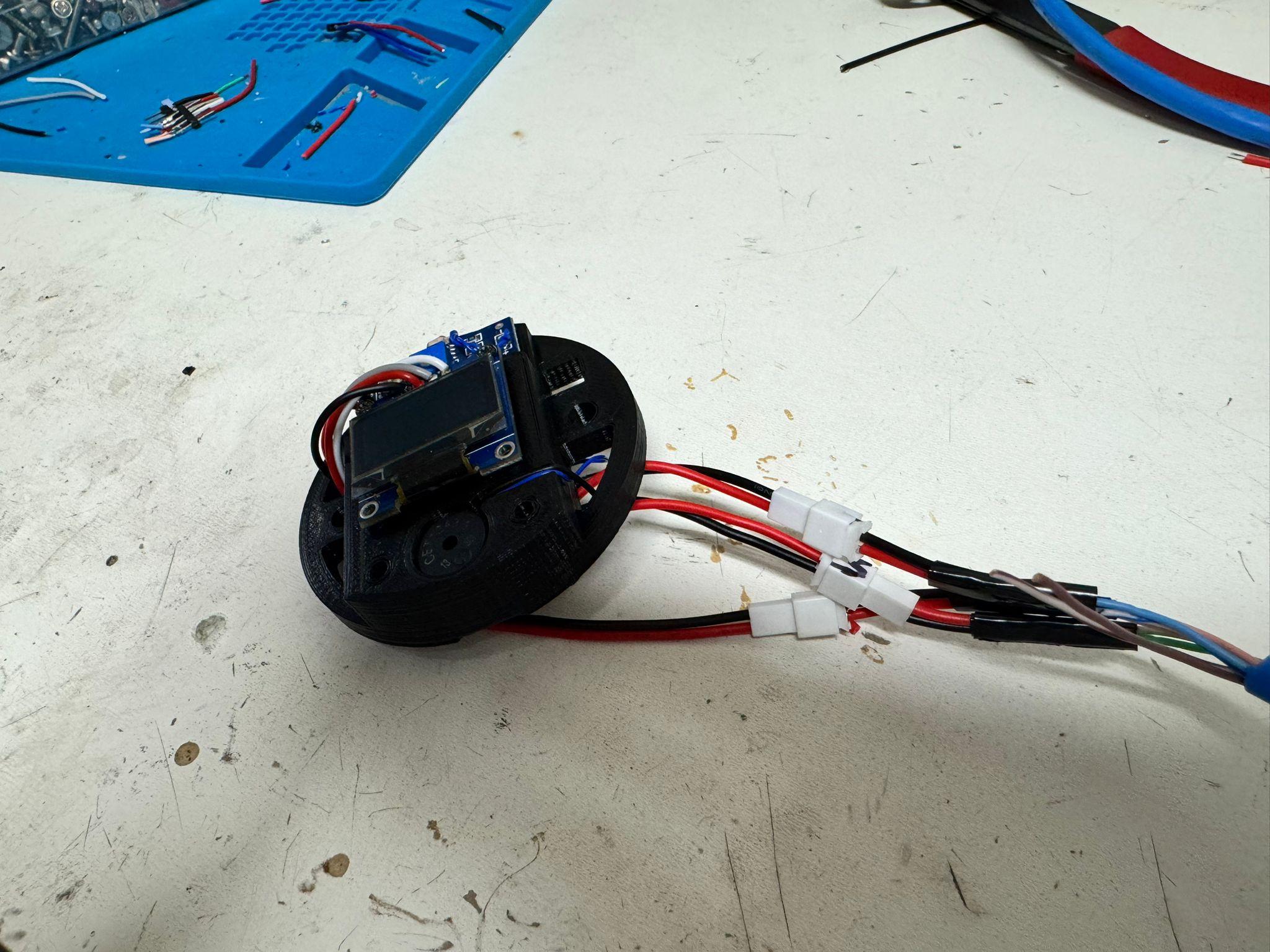
To make things more modular, I added JST connectors between the Ethernet cable harness and the ESP32. While not required, this will make servicing/modification significantly easier. Wire the harness as shown:
- Green/White → VIN
- Green → GND
- Orange/White → 3V3
- Orange → GND
- Blue/White→ GPIO13
- Blue: → GPIO12
- Brown/White → Unused
- Brown → Unused
Again, make sure to use a multimeter to check all connections.
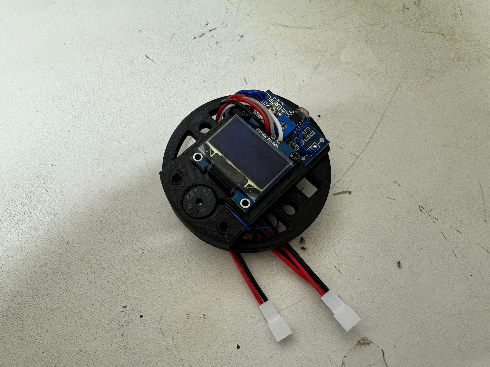
Assemble Monitor Shell
Now that the electronics are wired and tested, it’s time to bring everything together into a sturdy, finished enclosure.
- Glue the Magnets
- Take the rear shell of the monitor enclosure.
- Using superglue or epoxy, securely attach the magnets into their designated recesses (make sure they are oriented correctly!).
- These magnets will allow the monitor module to easily attach to the softener's resin tank without screws or tape.
- Allow the glue to fully cure before proceeding.
- Install the Electronics Mount
- Place the electronics mount (the 3D-printed plate or bracket holding the ESP32, OLED, buzzer, etc.) into the front shell.
- Carefully orient it so the OLED screen aligns with the window and confirm the LDR peeks through the small hole at the top of the shell.
- Double-check that all wiring is tucked neatly inside without being pinched.
- Close the Enclosure
- Align the rear shell with the front shell, using the large cutout for the harness.
- Insert the M4 bolts into the mounting holes and tighten gently until snug. Do not overtighten, as this may crack the plastic.
At this point, the monitor module is fully assembled and ready for installation on the brine tank. Place the monitor and scale by your water softener, but don't place the brine tank on the scale yet! We will flash the code and calibrate the scale in the next step.
Flash Firmware and Calibrate
Why Calibration is Important
Each load cell (the small sensor inside the scale feet) has slight variations from manufacturing. Calibration ensures the ESP32 knows how to translate the sensor signals into accurate pounds of salt in your tank. Without calibration, the readings may be off by several pounds.
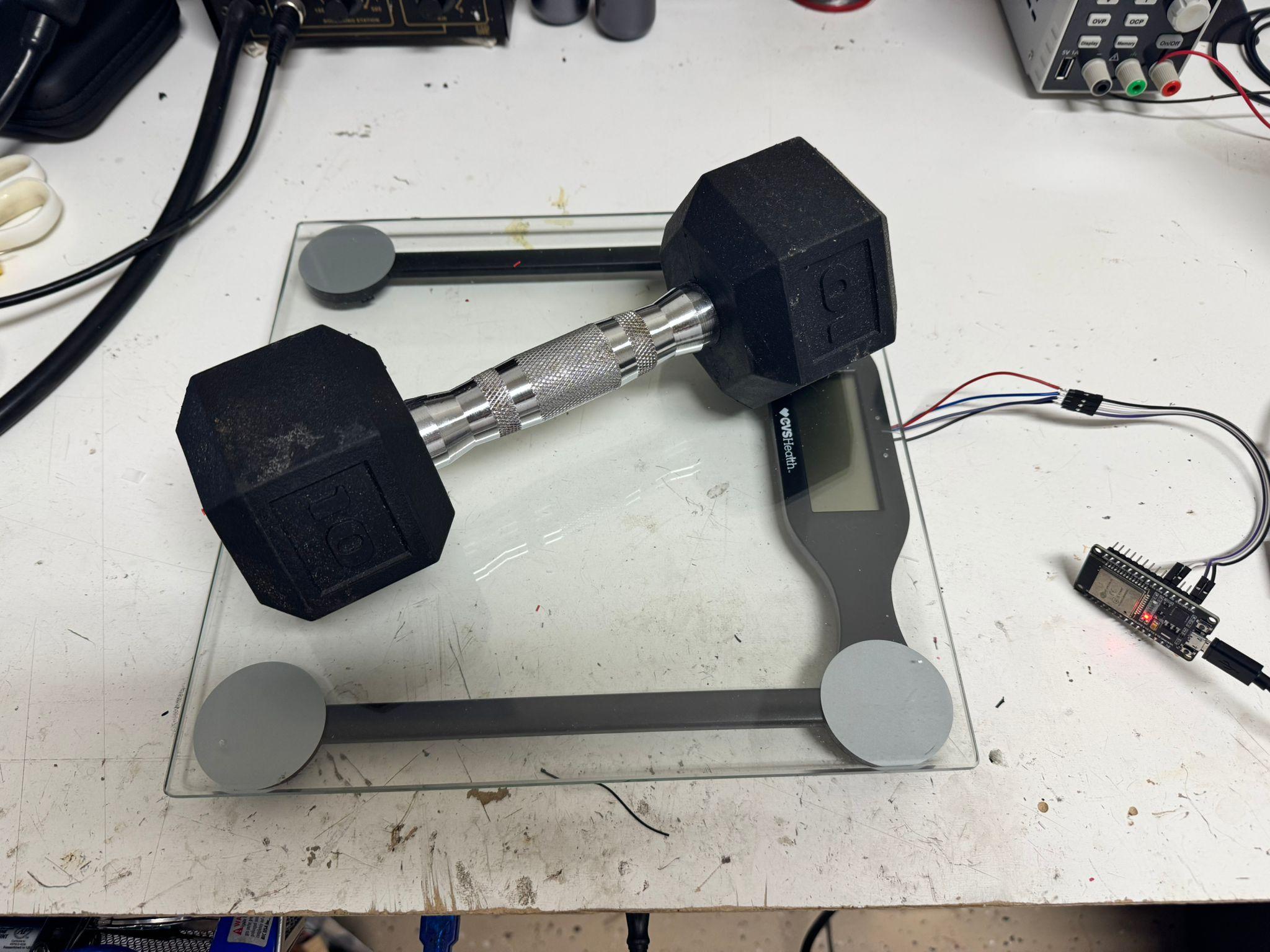
About the Calibration Weight
The firmware expects a 10lb weight during calibration (I used a dumbbell). If you don’t have a 10lb weight, you can:
- Use another object with a known, fixed weight (e.g., 5lb, 20lb, or even a bag of rice/flour).
- In that case, you’ll need to adjust the calibration constant in the firmware code before flashing, so the ESP32 knows what weight you’re using.
Calibration Procedure
- Flash the Firmware
- Connect a USB cable to the underside of the monitor module and plug it into your computer.
- Flash the provided firmware (SaltScale_V2.ino) to the ESP32.
- Leave the 5V barrel jack unplugged during this step.
- Power Up the System
- Once flashing is complete, unplug the USB cable.
- Plug in the 5V barrel jack to power the system normally.
- Enter Calibration Mode
- Using a toothpick or pin, press and hold the recessed button on the monitor for 5 seconds.
- The OLED screen will guide you through the calibration process.
- Calibrate the Scale
- Ensure the scale is on the same flat, stable surface where the softener tank will sit, with nothing on top.
- Follow the on-screen prompts.
- When prompted, place your 10lb calibration weight (or alternate known weight).
- Verify that the display reads the correct weight.
- Finalize Calibration and Mounting
- Remove the calibration weight.
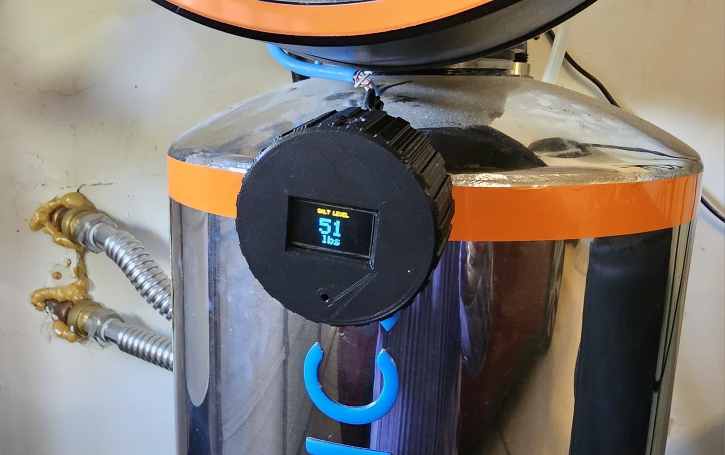
- Place your brine tank on the scale.
- Magnetically attach the monitor to the resin tank (or mount at eye-level as desired).
- Calibration is complete! The system is now ready for real-world use.
Troubleshooting
- If the reading for the calibration weight is not accurate, repeat the routine.
- Ensure the scale is on a level surface with no vibrations.
- If results vary widely, double-check that all 4 sensors are wired securely.
Downloads
General Usage
The water softener salt scale is now ready to use! Here’s what to expect during operation:
- Weight Display
- The monitor will continuously show the weight of your brine tank in pounds.
- This lets you easily track how much salt remains without opening the tank.
- Automatic Display Power Saving
- In low light conditions, the monitor will automatically turn off the OLED display.
- This prevents screen burn-in and saves power.
- The display will turn back on automatically when light is detected.
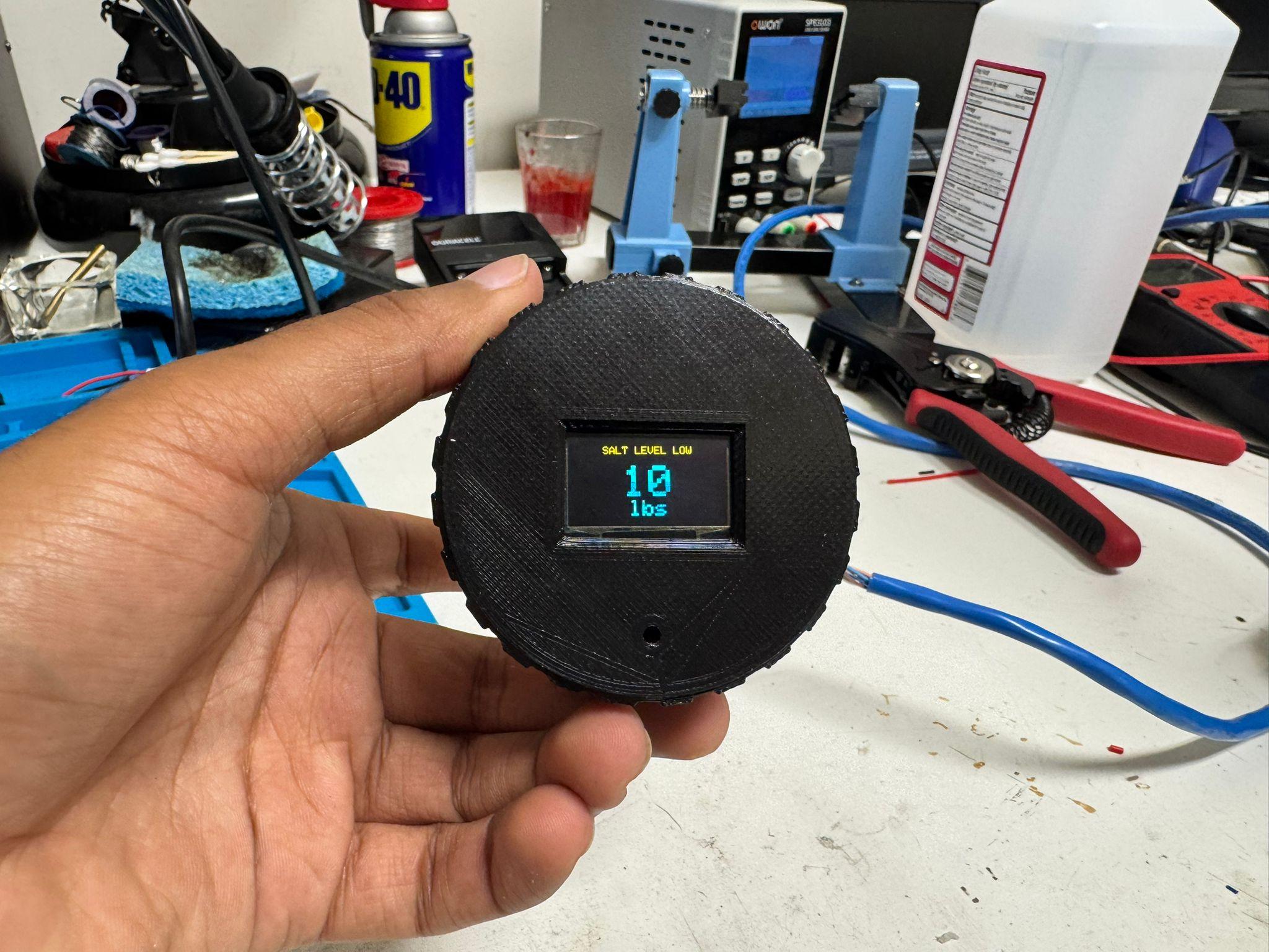
- Low-Salt Alert
- If the measured weight drops below 25 lbs, the system will issue a brief beep every minute (similar to a smoke detector chirp).
- This is your reminder to add salt before your water softener runs out.
- Recalibration Button
- The small button on the back of the monitor can be pressed and held to re-run the calibration routine.
- Important: The brine tank must be removed from the scale during recalibration. Otherwise, the readings will be incorrect.
With these features, your system will automatically keep you informed about your water softener’s salt level, helping you avoid unexpected soft water downtime.
I hope you liked this project! Don't forget to vote for it in the Home Repairs Contest!