Weasley Clock
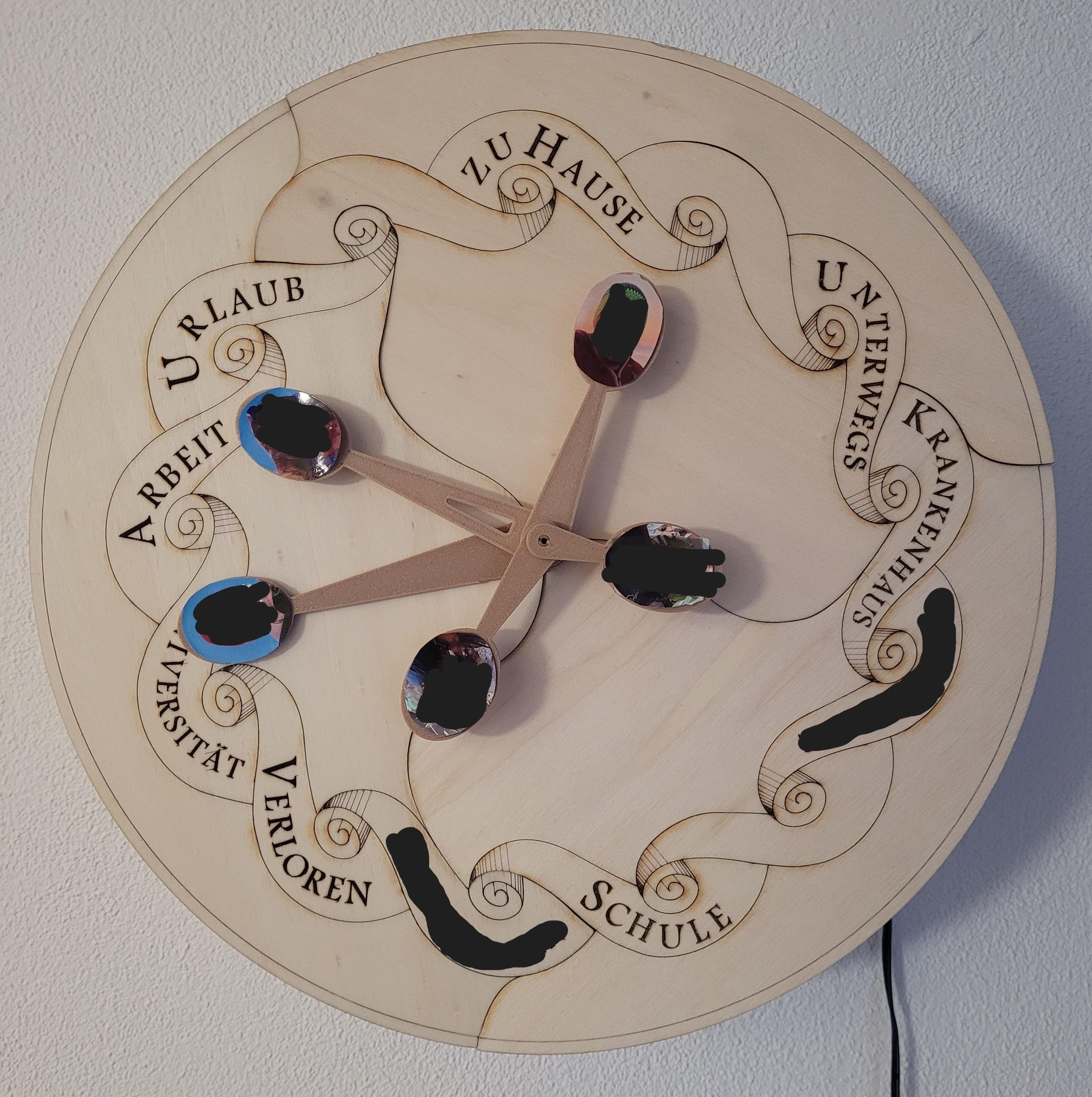
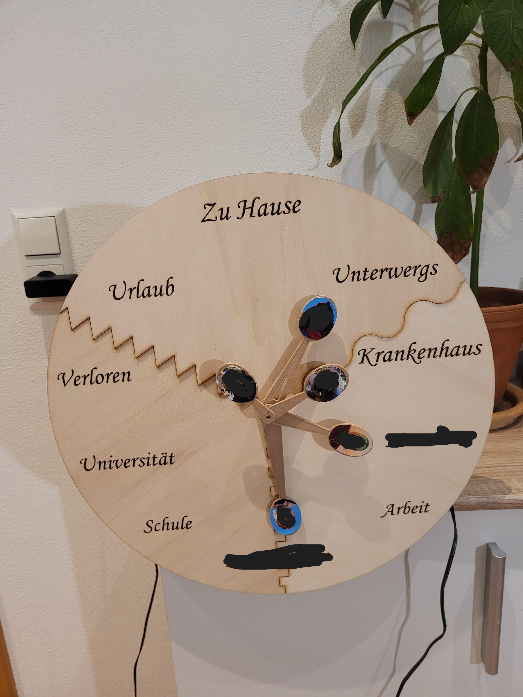
I can not remember when exactly, but at one point I thought it would be very cool to have a proper working Weasley. It sholuld be a gift for my mom, who loves Harry Potter and is a huge fan of Molly Weasley.
So I designed and produced this clock, which can display the location of 5 people, ever via GPS tracking or by using an app on each users phone.
This instruction is currently in the making. The project is to complex to explain everything in detail, but feel free to already comment, what you want to know in more detail.
Supplies
Material you need:
- Microcontroller (ESP32 with enough GPIO Pins)
- 3D Filament for housing, gears and pointers
- Wood for the clock display
- 5 stepper motors with drivers
- jumper cables
- jumper sockets and connectors
- perforated circuit board
- 5 V Power supply
- Brass hollow sticks for each pointer with different diameter
- 2 bearing wheels
Tools:
- 3D Printer
- Wood laser
- Soldering Iron
Design the Clock Case
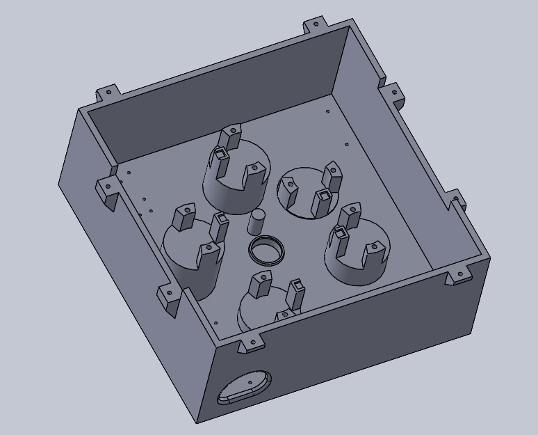
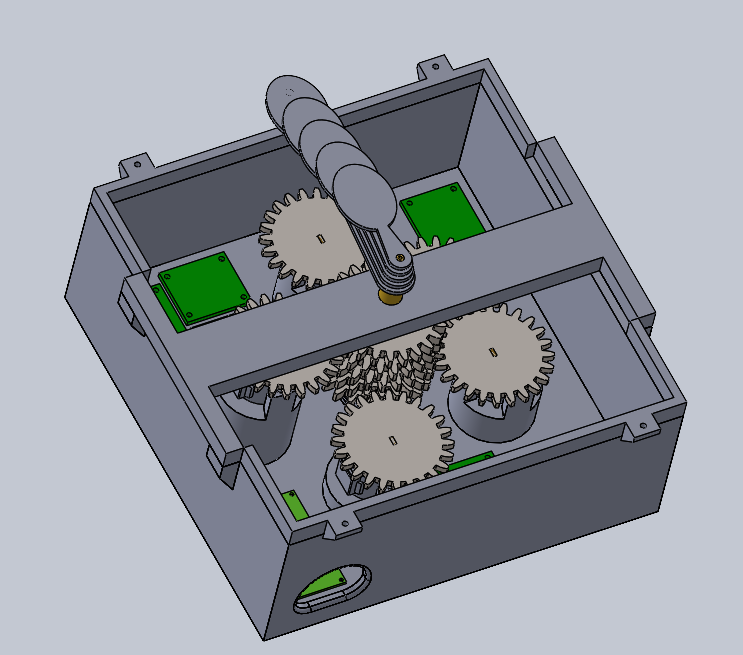
The first step is to think about how many pointers you need. Each pointer increases the complexibility.
Use your favourite CAD program to design the housing. It is important to place the motor sockets at different heights so that they can access different gears. As you 3D print your parts and everything is DIY, please give yourself enough space and tolerances.
Even more points to consider:
- Where do you place your motor driver boards?
- Where is the microcontroller sitting?
- How to route your cables?
- Where to bring in the power?
- How do you attach the dial to the housing?
Design and Plan the Other Components
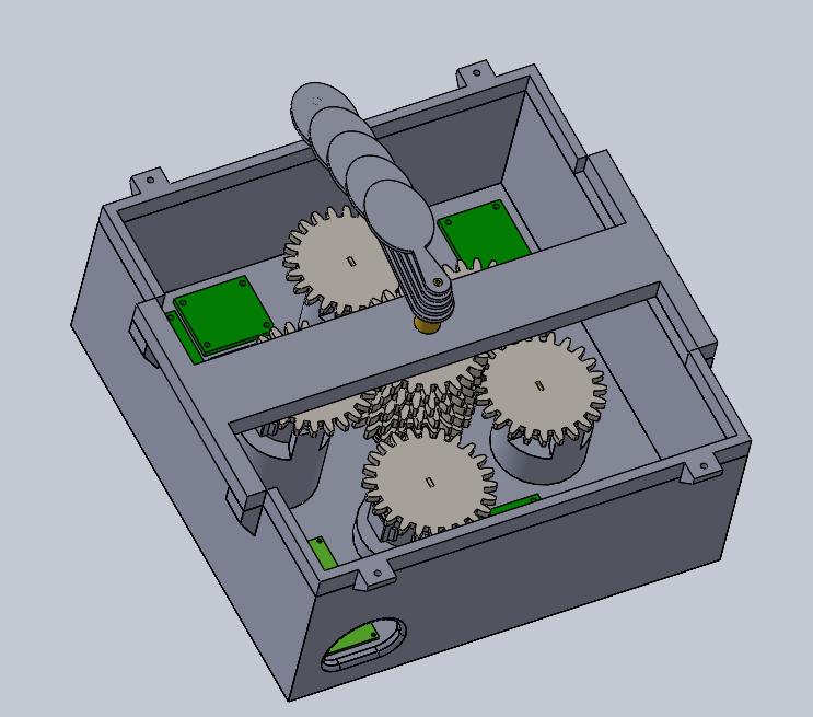
After you finish your first housing draft, start thinking about the components. You must house the stepper motors with drivers. For 5 pointers, you need 5 wheels on the motors and 5 wheels on the centre shaft. for the Controlling, you need a microcontroller (I used ESP 32). The microcontroller should be on a circuit board where you can attach the needed cables and connect the power. The power cable must enter the housing from outside.
The Center shaft with the 5 wheels must have a bearing. I used 2 bearing wheel. Maybe this is overengineered, and you can just mount the shaft in a hole in the housing.
What I find very helpful is to design an additional sleeve to support the shaft. This means the shaft is not held in place by the dial, so the dial can be easily removed.
After you included all your parts in your CAD, you will have to adjust the housing for sure. Take your time. It makes it simpler afterwards.
Print Your Housing, Gears and Optional Sleeve
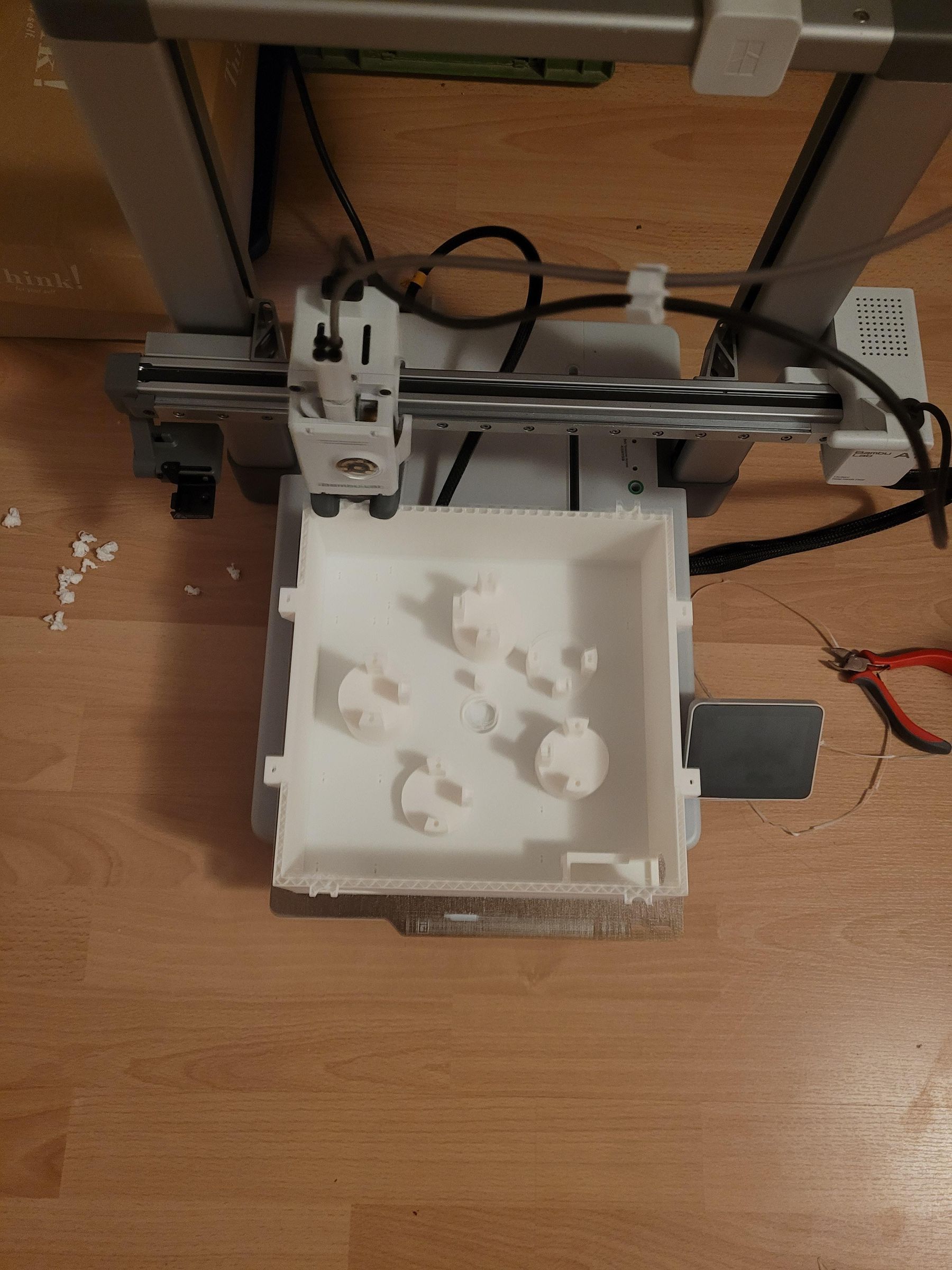
Now print your housing. It will probably take some time. You do not have to use spezial settings as it should be an nominal print. Only the huge base plate was a little tricky for my BambooLab. But in the end the printing plate just needed a proper cleaning.
Also print your gears. You can easily 3D print gears for the motor using a press fit. It worked well for me. It was a bit trickier with the central shafts. In the end, I used a few seconds of adhesive, a press fit and a key. It’s best to have a read through the next step.
Prepare the Centre Shaft
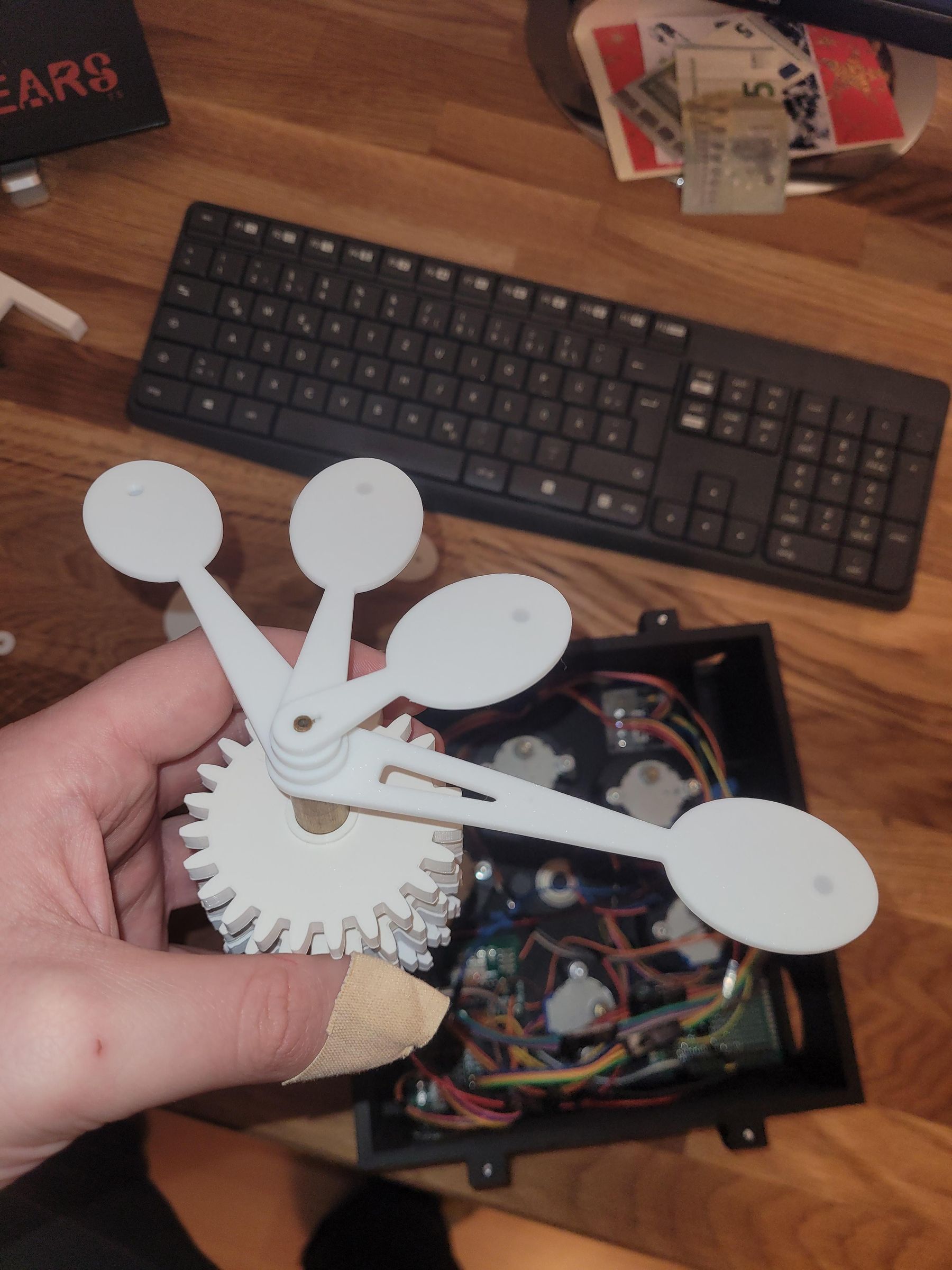
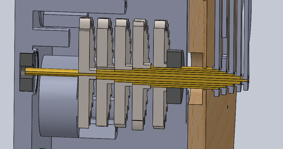
The clock hands all need shafts on which they can move independently. With 5 hands, that means 5 shafts. Supporting each one individually with ball bearings would be a huge and very complex undertaking. Fortunately, brass is self-lubricating and slides smoothly within itself. So I use five different hollow brass tubes. The first is 4 mm thick and has an internal diameter of 2 mm. The second has an internal diameter of 4 mm and an external diameter of 6 mm. This continues up to an outer diameter of 12 mm for the fifth shaft.
You can order tubes like these online. Usually, however, you’ll need to cut them to size yourself. I did this by hand. I’d recommend using a proper electric metal saw, though. The length is determined by the CAD model. Bear in mind that the shafts are slightly offset on the dial side so that the hands can be fitted onto them from above. Inside the housing, the shafts must also protrude to different depths. This allows the gears to be fitted from the other side. The gears themselves act as a lateral stop to prevent the shafts from slipping.
With this approach, the thickest shaft becomes the shortest.
To prevent the gears from spinning through, I recommend sawing the end face of the brass shafts slightly. The gears are then printed with a corresponding key.
Electronic Assembly
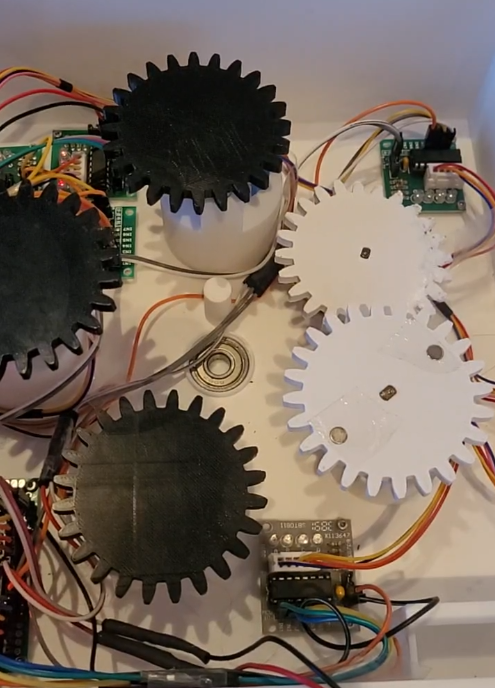
Now that all the components are there, you can assemble them. Fixate the circuit board for the microcontroller and the motor driver in the housing. screw/mount the stepper motors to the relevant positions. Now connect the driver and the motors with the cables. Afterwards, connect the motor driver with the microcontroller. Also, connect the power lines of the drivers to the circuit board.
Now it important to first test the motors. Flash the microcontroller with a simple program that just lets the motors run for some time. This helps you to fix bugs early. Important. Just connect the external power supply when you disconnected the computer from the microcontroller. Otherwise, your computer can get damaged.
Assemble Wheels and Shaft
Once the motors are running reliably, you can turn your attention to the gears. In my method, I first slot the brass tubes together. I then slide the 5 gears onto the tubes one by one and glue them in place. Afterwards, make absolutely sure that the shafts still turn freely and that the gears do not slip.
Now insert the ball bearing into the housing, followed by the shaft with the gear wheels. Only now should the other 5 gear wheels be fitted onto the 5 motors. This makes it easier to fit the shaft with the gear wheels. Otherwise, it will be difficult later on. Now insert the second ball bearing into the support bracket. Finally, slide the bracket over the shaft. Secure the bracket to the housing.
Now you should test the motors again and check whether the gears on the shaft rotate independently.
Congratulations, you have managed the hardest part!!!
Prepare the Dial and Hands
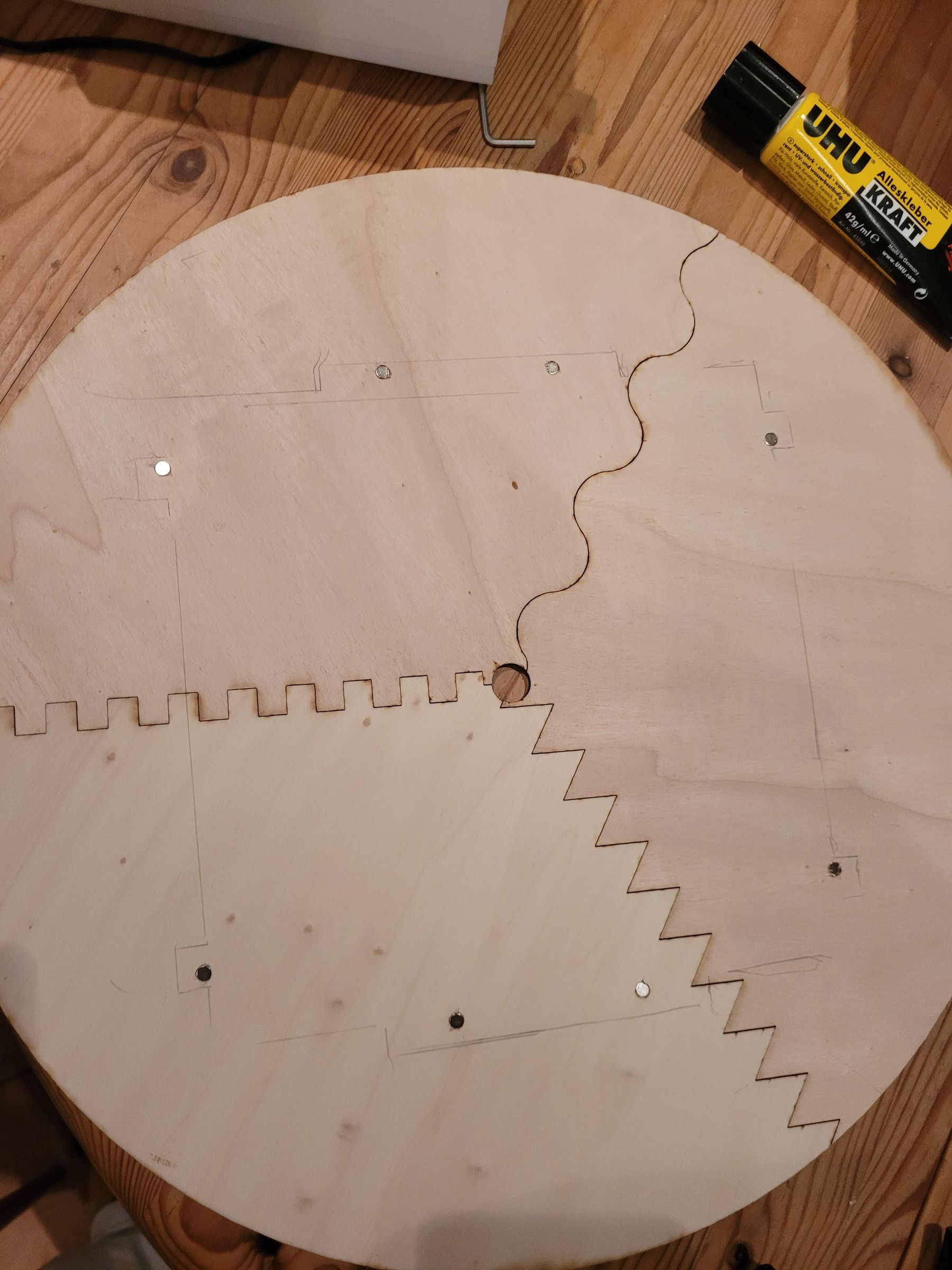
Now it’s time to design the dial. Think about the elements you want to include. You’re free to get creative with the rest of the design. Bear in mind, however, that the more hands you have, the larger the dial should be. Otherwise, the hands will cover the text.
Once the design is finished, you can feed it into the laser cutter. For the wood, I used thin hardwood from the DIY store. A tip: make the dial from several elements that you can attach around the shaft. That way, you can remove the dial without taking the hands off.
Of course, you can also paint your dial yourself or make it in some other way. There are plenty of options here.
The Hands of a Clock
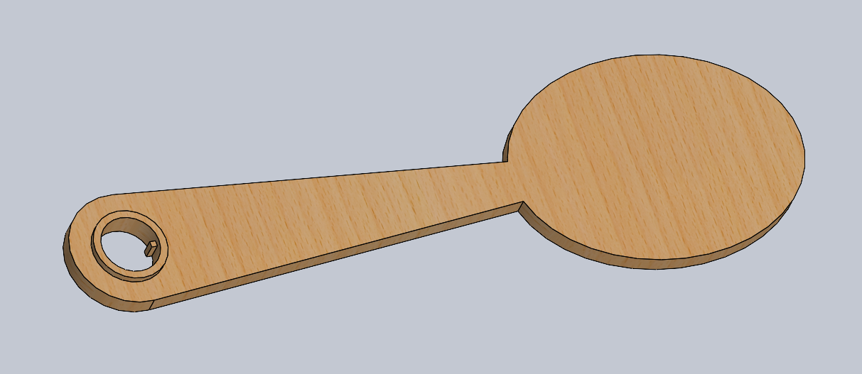
The same applies to the hands. I 3D-printed the hands. This allowed me to experiment with the press fit, which I think is the best option. For aesthetic reasons, however, I would also have liked to have laser-cut the hands from wood. In the end, I at least used wood filament. That was a nice compromise. I then stuck printed photos of my family onto the hands.
On tipp: Cut small edges in the brass elements and print keyways for connecting the shaft and the clock hand
MQTT Server
To make the clock work by magic, it needs to know where the hands should be. I used MQTT for this. You can set up a free server on HiveMQ, for example. Messages are then sent to this server, which the clock retrieves and uses to control the hands.
Now It Is Time to Run the Code
You can flash the code on the microcontroller. I put some parts of my code here: https://github.com/Lake-Projects/Weasley_Clock.git
You can use them as orientation, but with AI it is very simple to code it. I use the free App IoT MQTT Panel to control the clock. You can install the app on each users phone.
Or if you want to have it as real magic, use the app own tracks. With this app you can define areas and send automatic mqtt messages to the server.