Whirlwind 3 - PC to JAMMA Arcade Interface
by baritonomarchetto in Circuits > Electronics
78 Views, 1 Favorites, 0 Comments
Whirlwind 3 - PC to JAMMA Arcade Interface
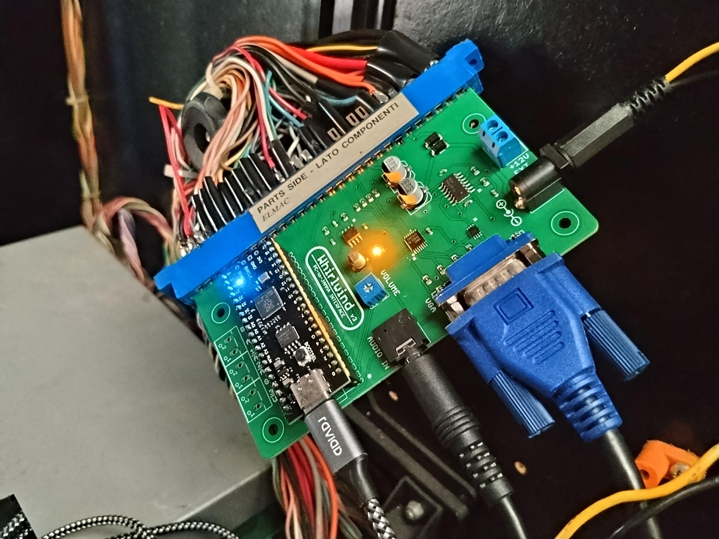
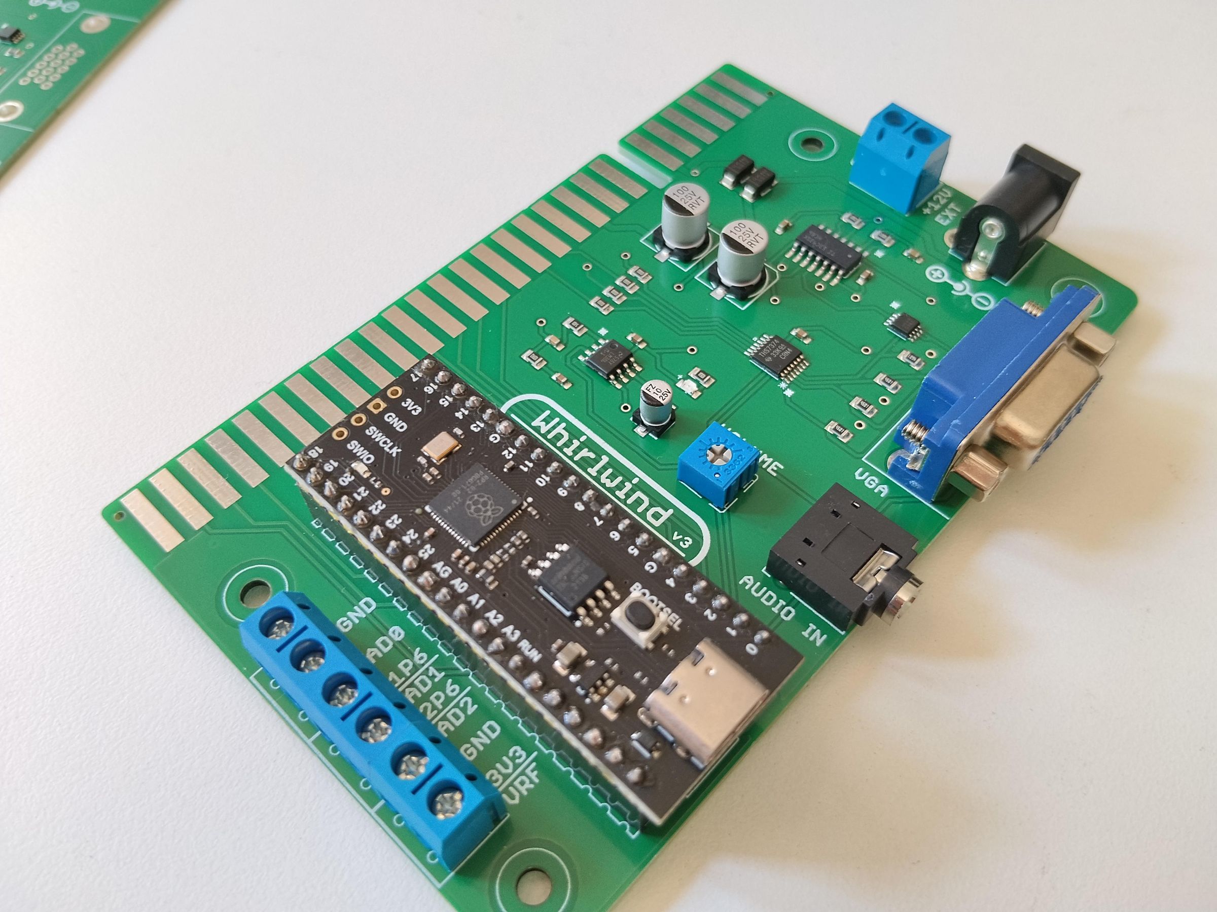
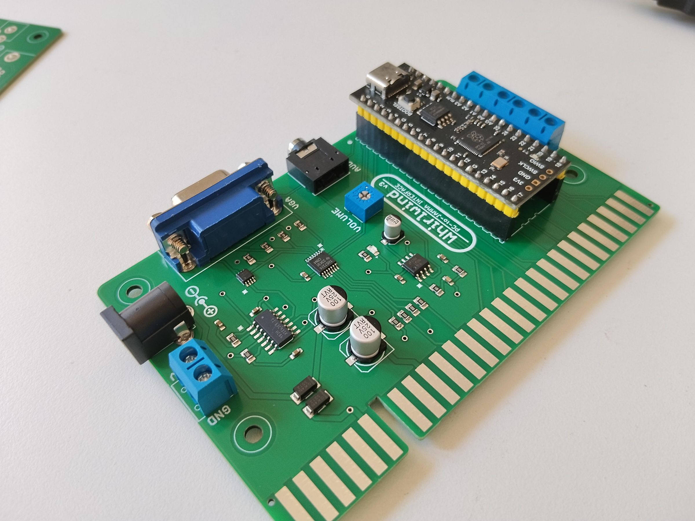
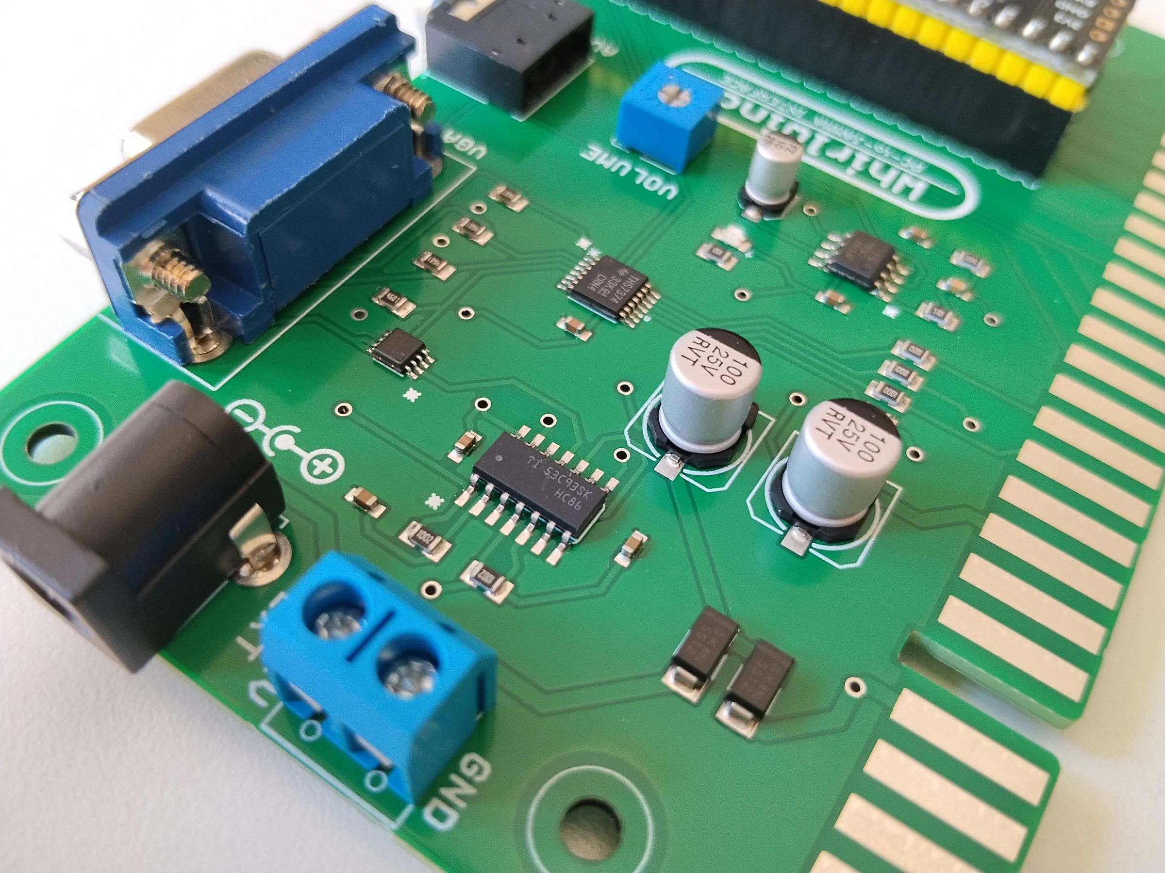
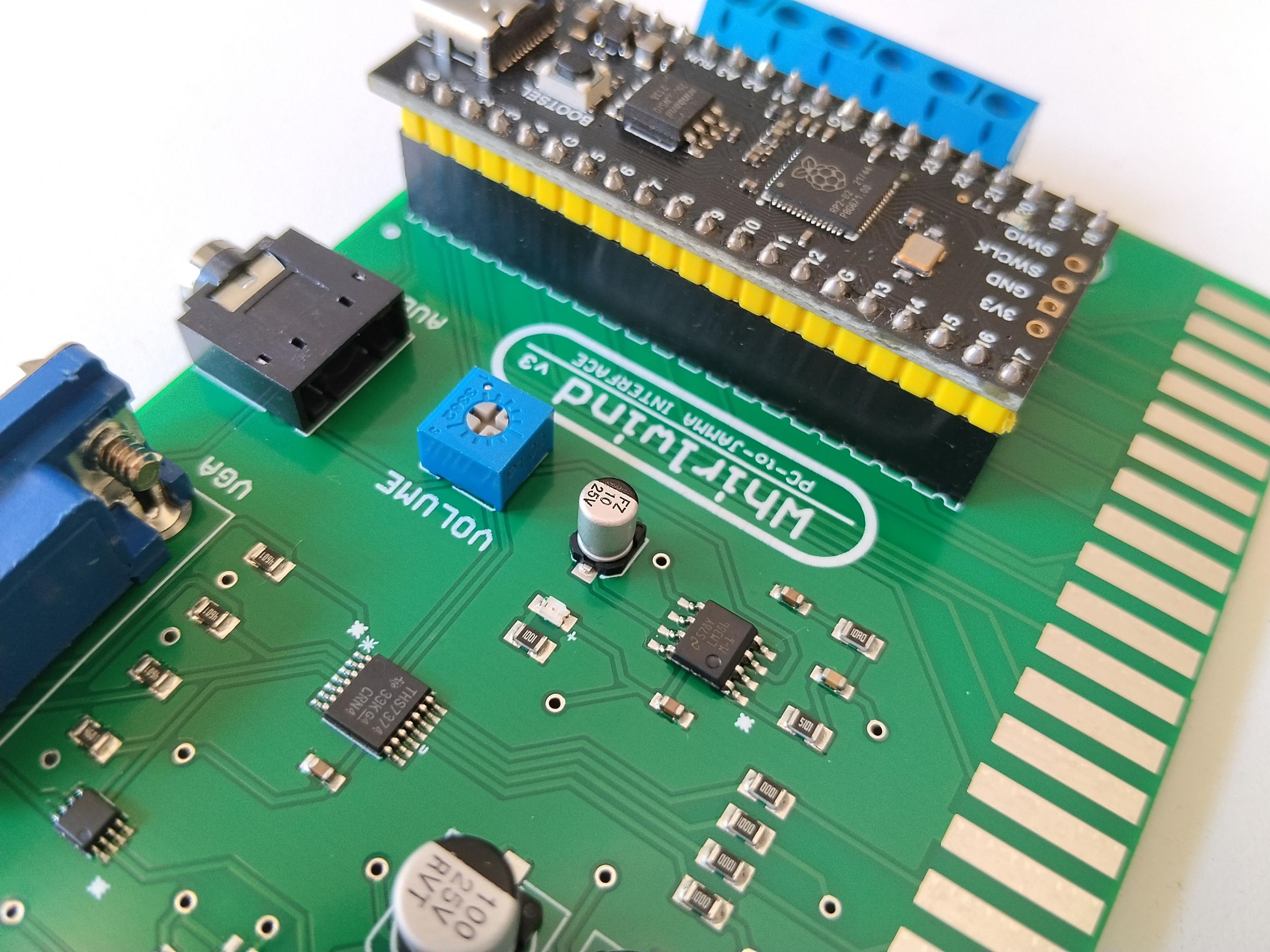
What I used to call "Jammarduino" is my longer-lived project. It's a matter of fact that I started Instructing with the very first prototype of that PC-to-jamma interface in 2017 (>>HERE<< a link to that instructable).
That work was the proof of concept of a cheap, DIY arcade interface board, featuring more than commercial products available at the time (and today).
Then Earthshaker followed, a low cost and trimmed down version based on 32u4 microprocessors. This was developed for those cabinets with a limited number of inputs, like one player cabs and JAMMA racing cabinets. Super-cheap, but limited in maximun number of inputs.
It was then time for Monsterbash, a bulky, arduino DUE based, full featured interface board. In more than one aspect a "nice copy" of the first Jammarduino prototype because of the dedicated PCB and built-in audio amplifier. The main con was the cost, especially in the years after the release because of the sky-rocketing of some microprocessor price.
The last developed was Whilwind: RP2040 based, my the best try, but still with some room for improvements.
And here we are, with an updated Whirlwind version!
In this Instructable I will show you Whirlwind v3, a DIY PC to JAMMA interface featuring:
- RP2040 microcontroller (cheap, fast and readily available)
- Open firmware
- Joystick and keyboard emulation (composite-HID device)
- CRT protection from out-of-spec sync frequencies
- Built-in XOR sync composition circuit (NEW)
- Built-in video amplification circuit
- Built-in audio amplifier
- built-in voltage buffering and shifting (NEW)
- Extended JAMMA pinout (2 players, up to 6 buttons per player)
I will describe it's circuits and main features.
I will share with you all the files you need to have the PCB printed and populated.
Let's go!
In case you are wondering: Whirlwind v2 has been drawn but never realized. It was a v1, THT version with improved c-sync circuit. I skipped that. I am getting old.
Supplies
Boards:
- 1x Whirlwind_v3 PCB
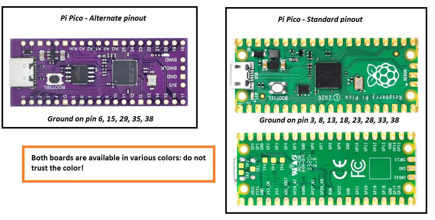
- 1x Raspberyy Pi Pico 30 INPUTS CLONE microcontroller board*
Video amplification circuit:
- 1x VGA PCB mount female connector (DB15, THT)
- 1x THS7374 video amplifier
- 4x 4.6K ohm resistors (0805)
- 4x 100 ohm resistor (0805)
- 1x 100 nF capacitor (0603)
Sync composition circuit
- 1x 74HC86D Quad XOR gate (SO14)
- 1x 74LVC2G125 dual line driver/buffer (SSOP08)
- 2x 10K resistors (0805)
- 2x 1uF capacitors (0603)
Audio amplification circuit:
- 1x LM386M audio amplifier
- 1x 10 uF electrolitic capacitor (0405)
- 2x 100 uF electrolitic capacitor (0605)
- 1x 22 nF capacitor (0603)
- 1x 100 nF capacitor (0603)
- 1x 10 ohm resistor (0805)
- 1x 5100 ohm resistor (0805)
- 1x 10K ohm trimpot/potentiometer (THT)
Others:
- 2x SS12 Schottky diodes
- 2x 20 pin female headers strip line, 2.54 mm spacing
- 1x DC barrel
- 1x 3.5 mm audio jack
- 4x W237-102 Wago screw clamps (optional)
- 1x VGA cable
- 1x audio cable
I will assume you have a soldering station and some tin by hand and you know how to use them.
*you are in the need for one of those Pi Pico clones with alternate pinout (see attached picture). These alternate pinout boards are commonly in purple color, but you can also see them in black. The same is true for standard pinout boards: often seen in green, but also in black. Do not trust the Pico PCB coloration but check the pinout.
A standard pinout Raspberry Pi Pico will not work here! It has a different and non compatible pinout with the Pi Pico 30 GPIOs clone this project is built around.
Main Features
Whirlwind main features are:
- Based on RP2040 microcontroller (cheap, fast and readily available)
- Open firmware
- Joystick and keyboard emulation (composite-HID device)
- CRT protection from out-of-spec sync frequencies
- Built-in XOR sync composition circuit (NEW)
- Built-in video amplification circuit
- Built-in audio amplifier (mono)
- built-in voltage buffering and shifting (NEW)
- Extended JAMMA pinout (2 players, up to 6 buttons per player)
The main circuit revision since previous version is the sync composition and monitoring one. Where I first used a simple AND circuit made of one diode and a resistor to sum horizontal and vertical sync signals, I have now adopted a more robust integrated XOR gate.
Also related to the sync circuit is how the 5V negative sync signal is shifted to 3.3V (RP2040 is not 5V tolerant). The former voltage divider is now replaced by a dedicated buffer gate.
Yes, there's also another obvious difference: the adoption of surface mount devices (SMD). Not that I am getting lazier with age (It's more difficult for me to design SMT boards than THT), but some necessary component is already SMD-only (the video amp, with it's sub-mm pitch) so an assembly service is advised to be foreseen anyway.
Please notice: this board cannot force the VGA video signal to CGA or EGA resolutions by itself, but special softwares like soft15KHz or CRT emudrivers are needed.
Schematics and Circuits Description
Microcontroller Board
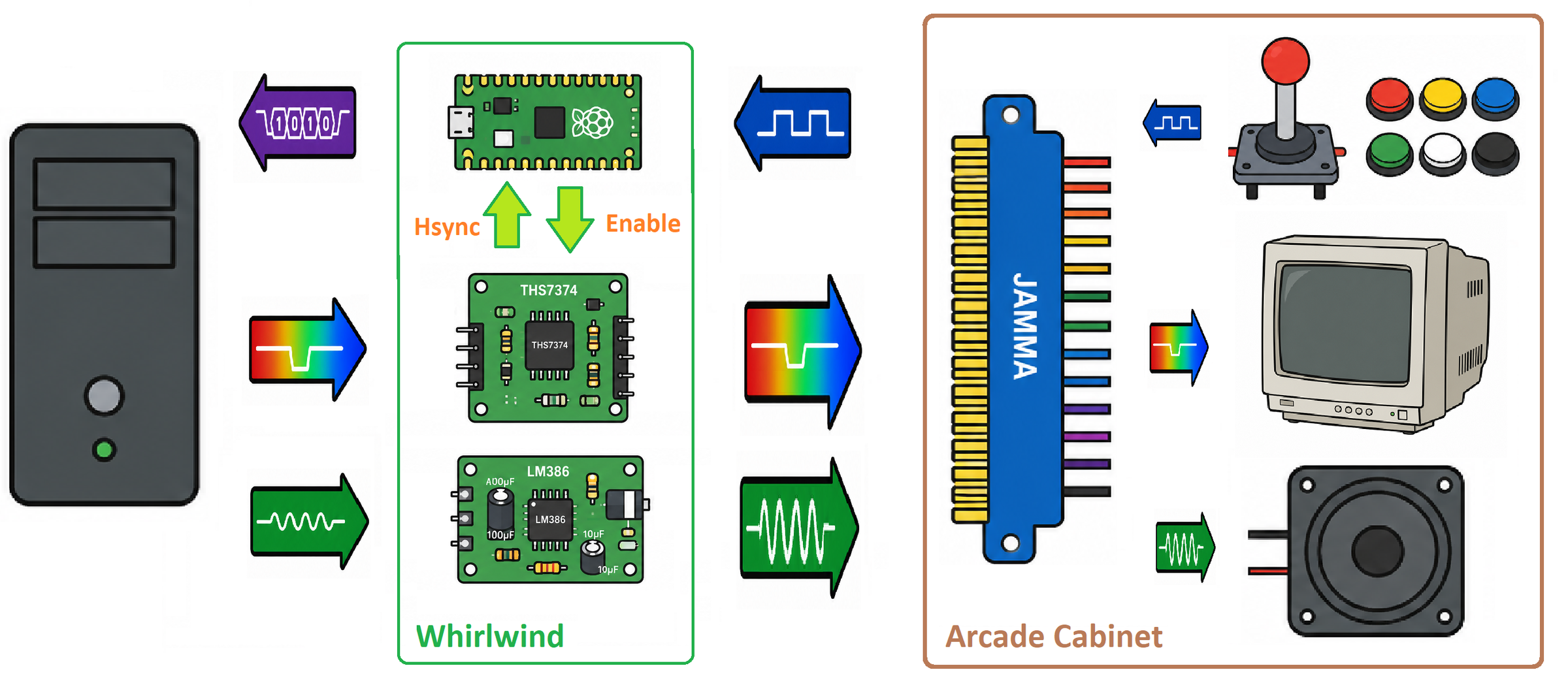
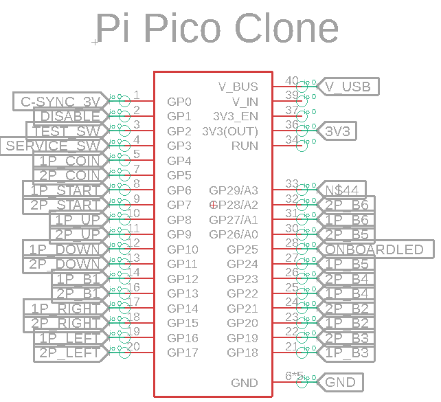
Raspberry Pi Pico (30 pin variant clone) is the brain of the project. It's in charge of:
(a) keeping track of user inputs
(b) Human Interface Device (HID) emulation (keyboard and/or joystick)
(c) monitoring the video sync frequency
There's not only the Pico, anyway. The description of all circuits follows.
Audio Amplifier
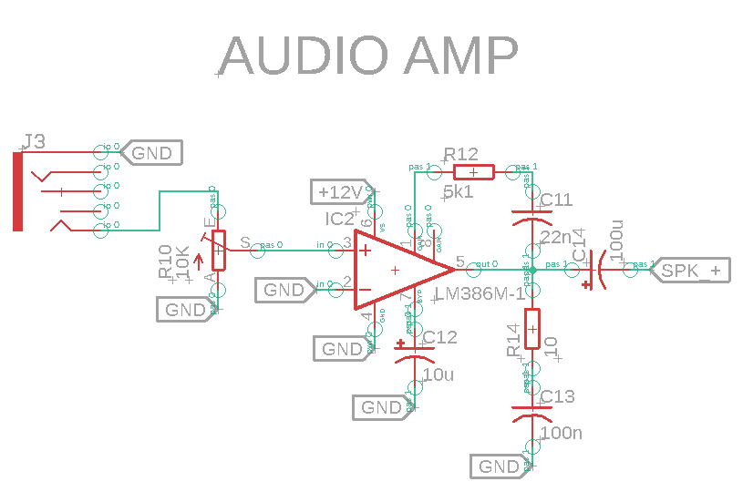
The built-in audio amplifier circuit is built around an LM386N. This is a power amplifier designed for use in low voltage consumer applications, which works well in single rail mode.
The gain is internally set to 20, which is more than enought for our use.
The volume is adjusted with a 10K on-board trimmer in voltage divider configuration.
The circuit is nothing particularly elaborate, with very low part count. It's mostly the one reported in the datasheet, with bass bost values set by ear.
This amplifier is good enought to drive a classic 3 W, 8 ohms speaker (those commonly installed in arcade cabinets), but will fry if you try to juice a lower impedance (i.e. 4 ohms) or higher power (i.e. 5 W) speaker.
My experience with these amps is that it's very important to use a legit IC... lesson learned the hard way.
This circuit calls for a source of +12V. It could be the cabinet power supply, or an external source. Even if two protection diodes are there, avoid juicing the board with bot +12V from the cabinet and +12V from an external source.
Video Amplification
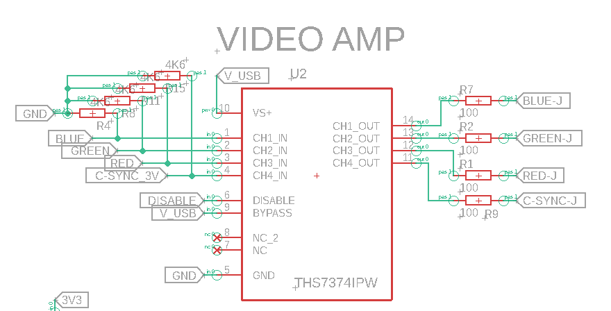
PC video card RGB signals are a little weak for a genuine arcade cabinet (0.7 Vpp vs 2-3 Vpp), then call for amplification. The amplifier of chioice is a THS7374, 4-Ch SDTV video amp with 9.5MHz filters and fixed 6dB gain (2X gain).
This video amplifier not only was born with this application in mind (which is always a good thing) but also has a very handy feature: a disable pin. This allows it's direct control from the microcontroller monitoring the sync frequency.
In all my previous "Jammarduino" iterations, the video amp output stage had a set of tree trimpots to help adjusting the R, G or B signal to fine tune the image colors. In practical application, these have little use. I then preferred to place three fixed current liming resistors in their place, with a value that should be ok for both arcade and TV CRT monitors (100 ohms).
Please notice that the 2X gain the THS7374 provides could be not sufficient to get a decent RGB amplification in some arcade monitors (i.e. Nanao). In such case a THS7375 (5X gain) could be a better choice. Untested!
Sync Management
JAMMA standard calls for composite sync, but VGA delivers separate horizontal/vertical sync signal.
While it may seem convenient to simply join the two H and V wires, this solution is strongly discouraged in electronics. Connecting two output stages directly can cause electrical conflicts and, in the long run, damage the video card's sync generation circuits. A simple diode combiner (AND logic) can be used (and I did with excellent results on my CRTs) but does not properly handle the polarity inversion of the pulses, producing a composite signal that could be unusable by some monitor.
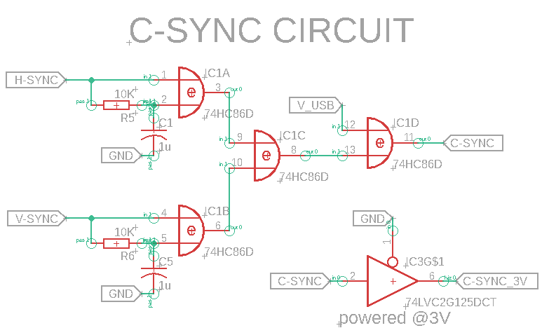
The circuit adopted here makes use of a XOR logic IC (74HC86). It can handle both positive and negative polarity sync signal at its inputs, then outputs a negative-polarity composite-sync signal.
Two RC networks (10 kΩ + capacitor) convert each sync signal into a steady DC voltage: high if the signal is positive, low if it is negative. Two XOR gates receive the H and V signals and the steady DC voltage. The XOR gates function as "logical rectifiers": If the signal is positive, it pass unchanged; if it is negative, it's inverted. After this stage, both H and V are always positive. The third XOR gate mixes the two positive signals. The output is what an arcade monitor needs: a stable, negative composite syncronization signal.
A branch of the C-sync is lowened to 3.3V by a buffer stage (74LVC2G125) powered @ 3.3V, ready to feed the Pi Pico GPIOs monitoring the frequency.
Power Management
The main voltage juicing most IC's and the Pi Pico itself (+5V) comes from the USB line.
The audio amplifier circuit is juiced by +12V coming from the cabinet power supply on the jamma connector, or an external power supply through the dedicated DC barrel. Two schottky diodes (one per line) protect in case you have both 12V sources connected. Avoid connecting both, anyway.
The voltage lowener on the sync line is powered @ 3.3V by the Pi Pico built-in voltage regulator.
The video amplifier can be powered @ 3.3V or 5V. Powering at 5V gives more room before video artifacts start, so you name the obvious choice.
To JAMMA or Not to JAMMA...
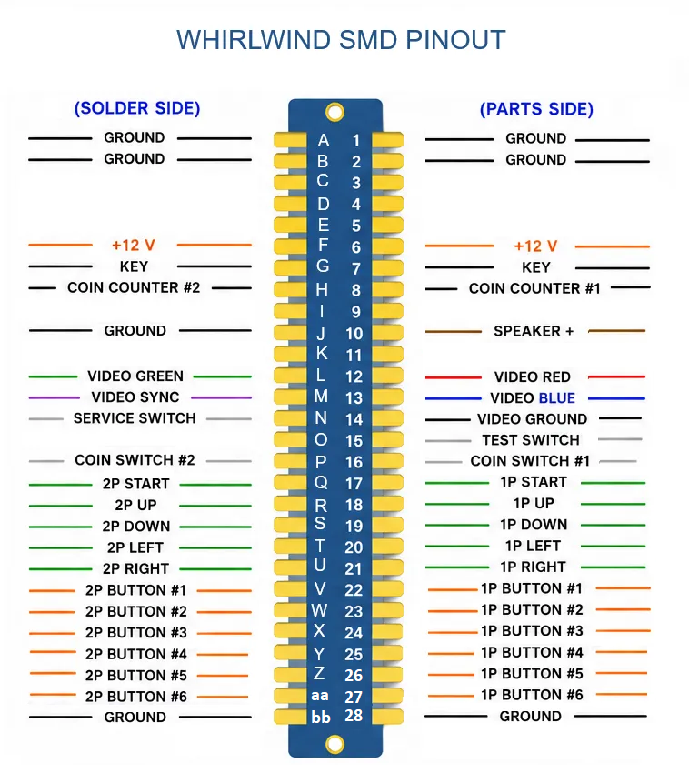
In the previous Whirlwind version I adopted a so called "JAMMA+" wiring. In this wiring players buttons are up to 5 each. We are all aware that one of the best coin-op games ever makes use of 6 (Street Fighter II anyone?) and my first solution was to make them available on screw connectors.
In this new version screw connectors are still there (there was the space, so...), but I have also directly wired P1 and P2 buttons 6 to the harness, in positions 27/aa. These are ground lines in jamma harness, so a simple modification to the harness is in the need. Just solder all cables going to pins 27/aa to 28/bb (ground) and P1/P2 button 6 to 27/aa.
After this wiring modification the harness is still JAMMA compatible ;)
Hey, my cabinet has 2 buttons always pressed now!
That's because in this interface pins "27" and "aa" are used as button pins instead of ground. If you have such issue and your cabinet has 6 buttons per player, you need to make the simple modification I described some line ago.
The Firmware
Having an open firmware gives the user the possibility to finely tune the interface behaviour.
In example, the "simplest" ( or should I say "more direct") way to handle inputs is a straight emulation of the HID of interest. Being it a keyboard, a gamepad or a mixed peripheral, turning your microcontrollor board into a HID is a very effective way to make good use of this interface. Another approach is the use of a software gamepad emulator in between our interface and games/emulator.
The first approach is perfect if you have to manage inputs only (like in this case), but could be limiting if outputs have to be considered.
This firmware transforms a Raspberry Pi Pico into a fully-featured PC-to-JAMMA interface, bridging arcade cabinet controls with a PC via USB while simultaneously managing video synchronization for CRT monitors.
It makes good use of both RP2040 cores, dedicating the first one to main control loop handling ( debouncing inputs, managing the shift state machine, and sending USB HID commands), the second one to video sync monitor tasks, continuously sampling the horizontal sync (H-sync) signal without interfering with input responsiveness.
The firmware handles all 26 physical inputs (joystick directions, action buttons, coin slots, service, and test switches) using internal pull-up resistors, by emulating a multi-HID device (keyboard and gamepad).
Implements a non-blocking 40 ms debounce filter on every input, ensuring clean and reliable button detection.
USB commands are sent only on state changes to minimize bus traffic.
Player 1 START button acts as a modifier key, giveing menu diving options to the user: a short press (< 2 seconds) sends a standard START pulse on release. Long press (≥ 2 seconds) activates SHIFT mode while held. In this mode, all other buttons send their shifted (alternate) keycodes (e.g., ESC, TAB, TILDE) instead of their normal values.
The firmware simultaneously emulates both a USB joystick and a USB keyboard. Direct inputs Joystick codes (1–32) are sent thanks to Matthew Heironimus Joystick library. Keyboard ASCII codes (> 32) are sent via the Arduino Keyboard library
The code actively protects the display from out-of-range signals by measuring the H-sync pulse period. If the detected frequency matches the safe 15 kHz range, the video signal is enabled (DisablePin goes LOW, visual feedback LED turns ON). Otherwise, the video output is disabled to protect the monitor from damage. This feature can be entirely disabled via the SYNC_MONITOR_ACTIVE macro if not needed.
All input-to-key mappings are stored in flash memory, saving precious RAM. Each entry defines the physical GPIO pin and HID codes (normal and shifted). This design allows easy customization of the button layout without rewriting the core logic.
SMD Tips and Tricks
This project uses surface mount devices (SMD) and I opted for JLCPCB SMT assembly service because:
(1) they sponsor me :D
(2) honestly I have always been very happy with the results.
Dealing with SMDs is more articulated than with through hole parts, but with the help of THESE instructions and JLCPCB online submission form everything went smooth and well.
I took some notes about the "criticalities" I found during my experiences with SMD assembly.
Here are some hints, for my and yours future use.
- Triple check your design before submission, by running your software design rule check (DRC) and electrical rule check (ERC). It will be difficult to fix those after the realization (SMD, people...).
- Check any single component authomatically chosen by JLCPCB site to be sure it fits the design. It happened to me, in example, that a resistor network was misinterpreted as a regular resitor. You will spot it immediately by looking at rendered PCB's components.
- By carefully looking at rendered PCB, you also will spot with ease wrong orientation or even completely misplaced ICs. About misplacements, if any, you cannot move ICs (their position is set by CPL file) but JLCPCB engineers will take care of it, no problem ;)
- The board rendering screen is a good place to check for missing components. Carefully go though all the board to be sure that all components are there and go back if something is missing.
- Components selection is the most critical (and funniest, in my opinion) phase. If the automatic selected part is not available or in inventory shortage, do not desperate! Use generic term in the part research field. In example: use 74HC14 instead of CD74HC14M and more options will be available.
- When you are done with components selection, save your components list in the shopping chart. This is because it could be the case you want to make some modification to your design after that, and uploading a newly generated BOM will force you to check/select components once again. The shopping chart components list is saved in BOM format, so it will be a matter of uploading it to have all previously selected components directly listed.
Throughout the entire assembly planning process of your device, you never have the feeling of being left alone... an added value for me!
Acknowledgments

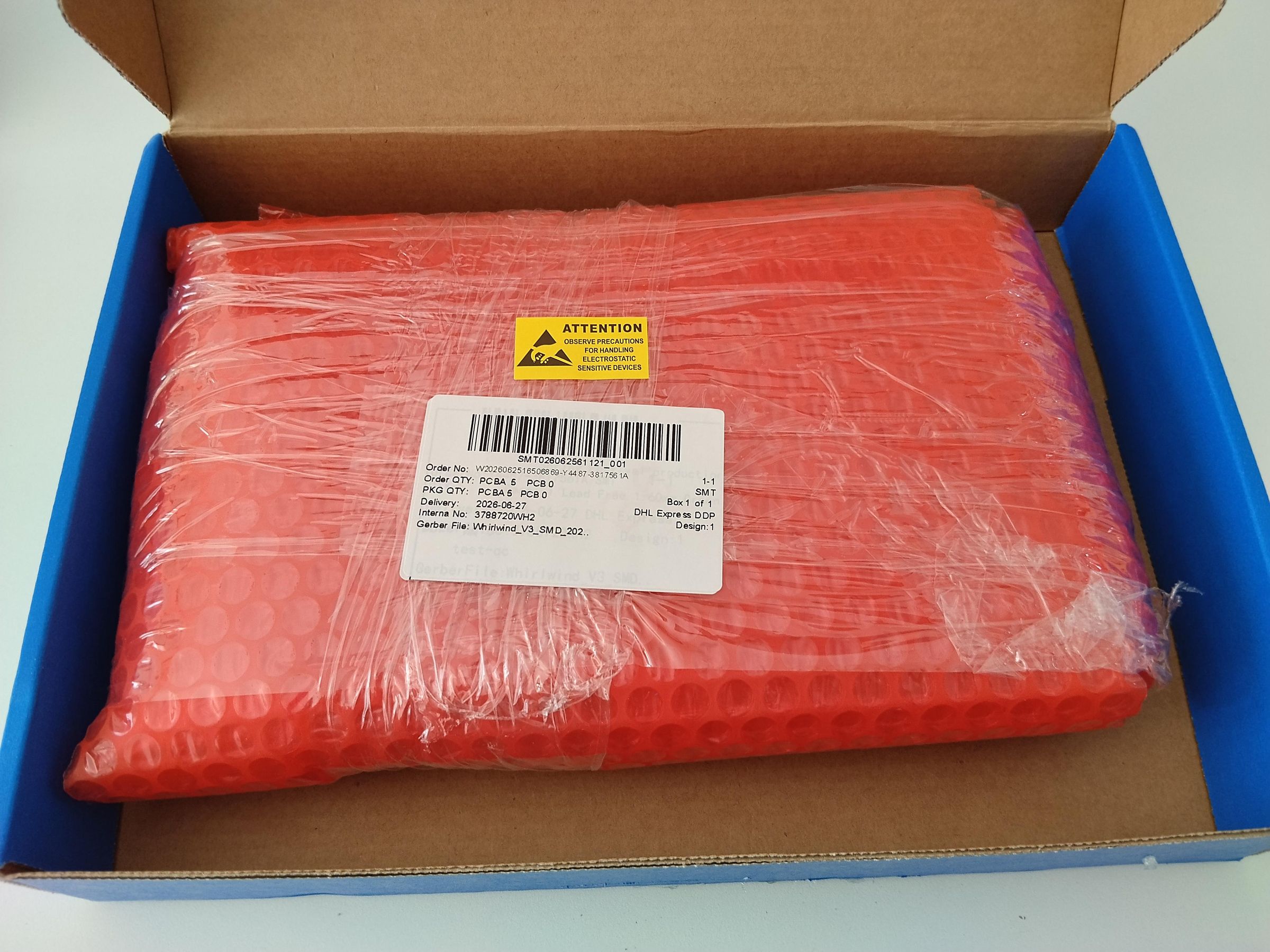
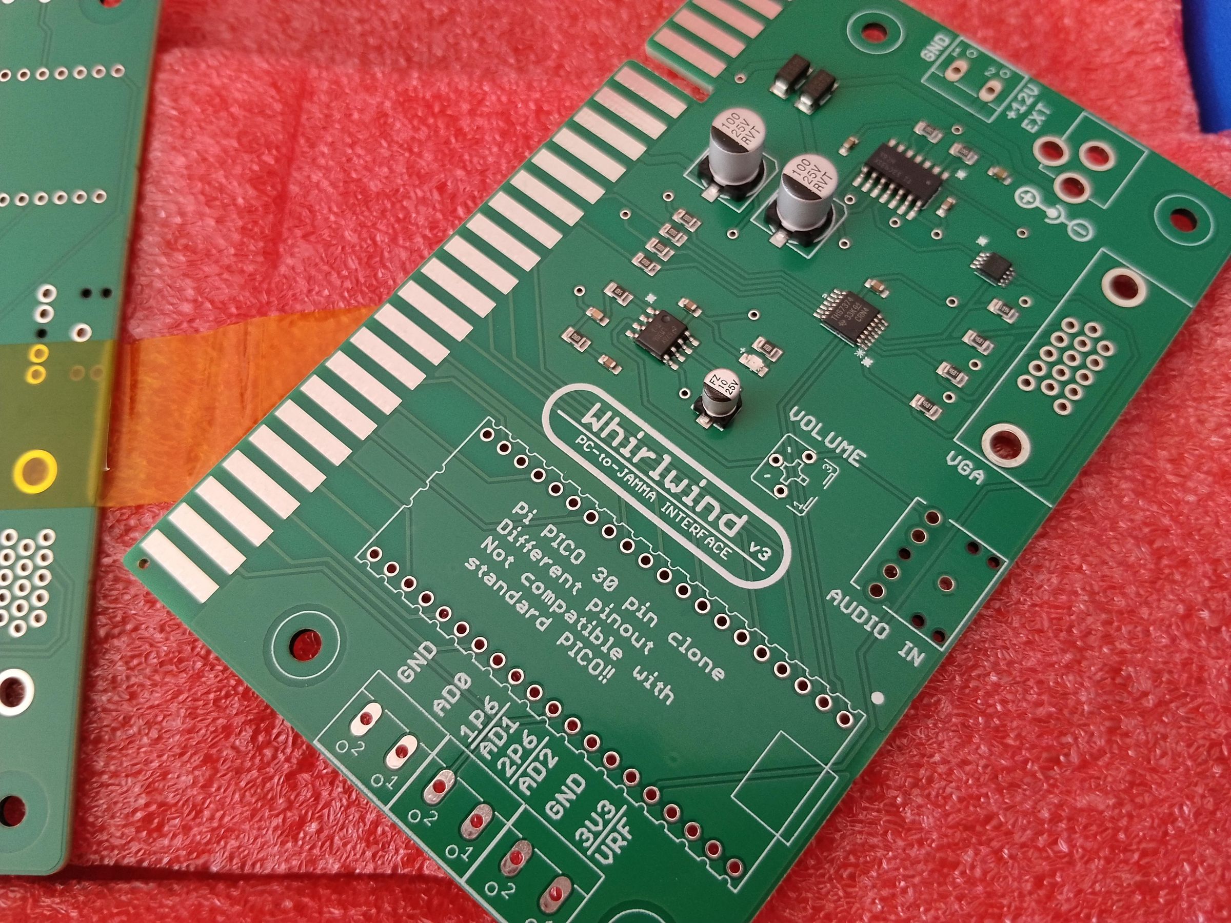
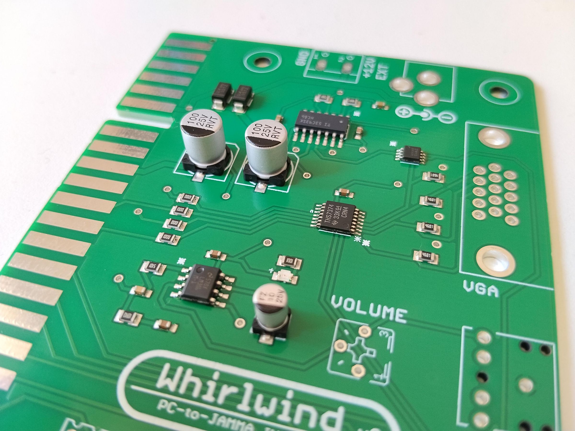
Many thanks goes to JLCPCB for sponsoring PCB manufacturing and SMD assembly for this project. It would have never gone this far without their material help.
JLCPCB is a high-tech manufacturer specialized in the production of high-reliable and cost-effective PCBs. They offer a flexible PCB assembly service with a huge library of more than 700.000 components in stock at today. This project made use of the service and everything went smooth and clean.
3D printing is part of their portfolio of services so one could create a full finished product, all in one place (note to self: start learning how to create 3D parts!).
What about nano-coated stencils for your SMD projects? You can take advantage of a coupon and test it at reduced price in these days.
By registering at JLCPCB site via THIS LINK (affiliated link) you will receive a series of coupons for your orders. Registering costs nothing, so it could be the right opportunity to give their service a due try ;)
All Gerber files and sketches I realized for this project are stored >>HERE<< (Github).