Wireless Dual Laser Turrets Glow in the Dark Printer Plotter 9000!
by lebdroid in Circuits > Lasers
731 Views, 9 Favorites, 0 Comments
Wireless Dual Laser Turrets Glow in the Dark Printer Plotter 9000!
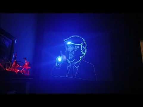
Dual laser turrets that draw on a glow-in-the-dark canvas. using esp32-s3-n16r8 (not the classic esp32 wroom) specifically for the psram, 4 28byj-48 stepper motors with their uln2003 driver boards. you can plot vectors like a pen plotter or raster-draw like an old CRT TV or hand draw. It is not that hard to recreate, the most difficult part of it all is calibration and dealing with the 28byj-48 backlash but a couple of rubber bands mitigated it. The software is on GitHub, and I have included the link. (https://github.com/lebdroid/laser-project)
also i want to be completely upfront, i am a hobbyist, not a professional, and this Instructables page simply show how I managed to complete this project. My way might not be the correct or safest method of doing it. lasers can be dangerous and so is working with electronics, please be safe and take safety precautions.
Supplies
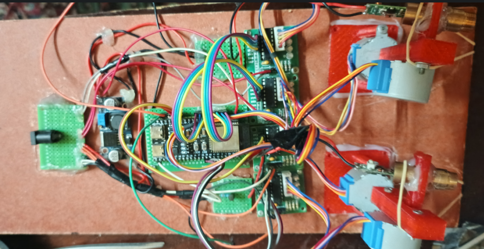
Project Component List
1. Microcontroller
- ESP32-S3 (N16R8 variant) Development Board (1 piece)
2. Motor Drivers
- ULN2003 Darlington Transistor Array Driver Boards (4 pieces)
3. Actuators
- 28BYJ-48 5V Stepper Motors (4 pieces)
4. Optical Modules
- 30mW 3.3V Violet or Blue Laser Modules (2 pieces. avoid Red lasers as they do not charge glow-in-the-dark materials)
5. Power Supply and Regulation
- 5V (4A or higher) Power Adapter (1 piece)
- DC Power Barrel Jack Female Connector (1 piece)
- DC-DC Buck Converter Module (1 piece)
6. Laser Control Circuitry
- NPN Transistors (2 pieces)
- 1k Ohm Resistors (2 pieces)
7. Other stuff
- Green Double-Sided Perfboards / Prototyping PCBs
- Jumper Wires
- Custom 3D-Printed Parts
- Fiberboard / MDF Sheet or a piece of wood to put the things on
- Foam board to be sprayed with glow in the dark paint
- Glow in the dark spray
Assemble the Turrets
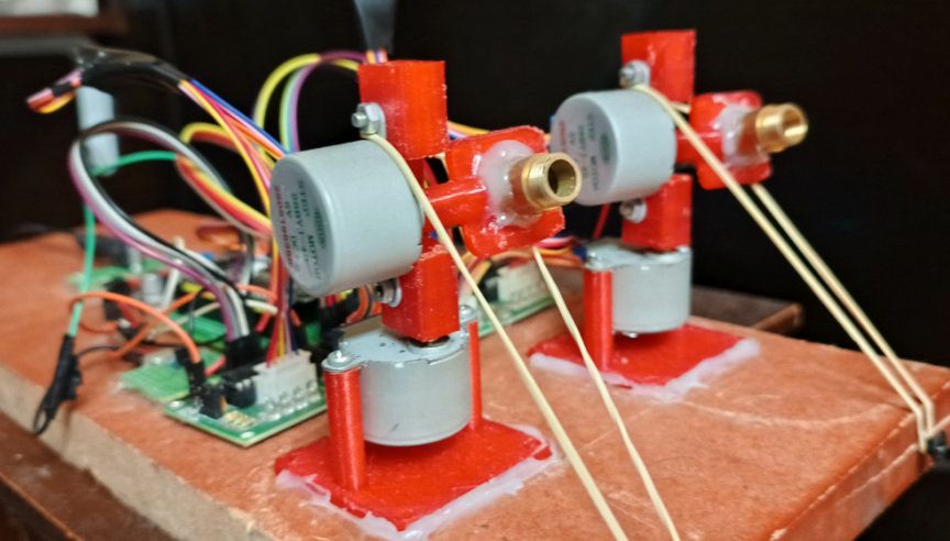
Assemble the brackets into two independent pan-tilt mechanisms (Turret A and Turret B). be as symmetrical as possible so calibration wouldn't turn into a nightmare.
hotglue the violet/blue laser module to the tilting head of each turret. and yes i used hotglue cause my holes are not perfect :"D
the 3d parts are designed on freecad and its the 1st time i use it and the 1st time to design anything 3d so please don't judge me too harshly, included the FCStd files the github repo incase you want to modify them to your needs. as for the screws and nuts i just took them from some old stuff i had. the screw holes in the 3d part are 3mm in diameter
The Wiring Begins 🫣
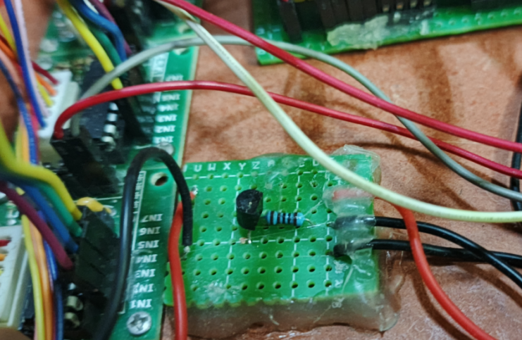
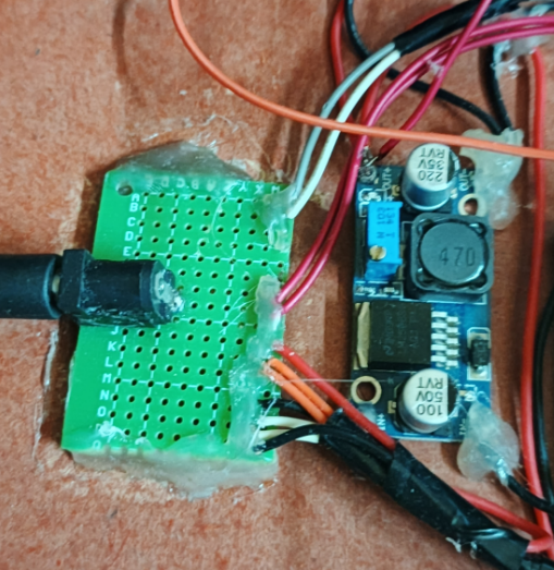
now this part might not be necessary depending on your laser module, some do have a signal input pin and you dont need to do this. and if not this is a simple driver board.
i cut a small piece of perfboard and soldered an NPN transistor in the middle.
i soldered one side of a 1kohm resistor to the base and then a wire to the other side of the resistor that needs to go to the esp32 as a signal wire so it could turn on/off the laser. the resistor is to limit the current sucked from the esp32 just incase..
then soldered a black wire to the emitter pin of the transistor that needs to get connected to the common ground rail.
and soldered another black wire to the collector pin of the transistor that needs to to get connected to the laser negative side.
now the red wires are the VCC (positive power supply voltage) they are not connected to the transistor, i just passed that wire through the board because it would look neat lol... it connects from the power source positive side (which is the DC-DC Buck Converter Module which is stepping down the 5v to 3.3v) to the laser's positive side.i did two of these one for each laser.
make sure you are using a proper transistor that fits the current needs of your lasers also verify the pins configuration emitter,base,collector before you start soldering things.
as for the main power source the 5v rail, i used a DC Power Barrel Jack Female Connector soldered it to a piece of perfboard and made a positive and negative rails, the Buck Converter Module gets powered from it also the motor drivers gets powered from it, so the positive and negative wires of the all 4 motor driver boards and the buck converters connects to it. and the buck converter is set to 3.3v supplies the lasers and the esp32 board.. watch out not to burn your esp32. double check the voltage on the buck converter output.
check if the buck converter current output can handle your two lasers and the esp32 board. in the images iam using an LM2596 Buck Converter to step down 5V to 3.3V which is causing the esp32 to reboot sometimes because the Lm2596 requires at least a 1.5V to 2V headroom between input and output to regulate properly but there are better alternatives for LM2596 that can handle stepping down 5v to 3.3v.
Wiring the ESP32
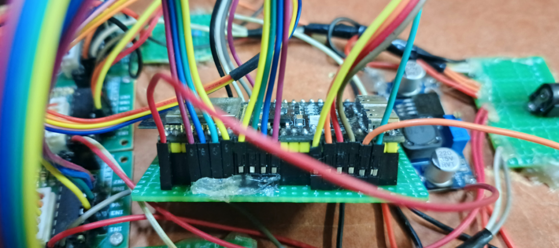
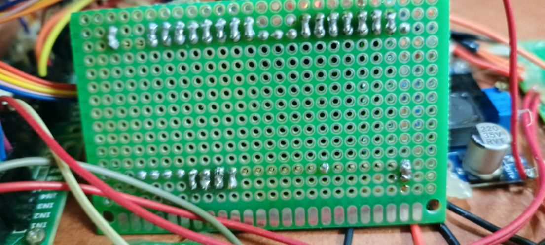
Wiring the the stepper motors with the driver boards is straight forward so im gonna skip this part and jump straight into the messy part. i used female header pins to mount the esp32 board so i could pluck it out and reuse it in other projects. as you can see in the images i used jumper wires female to male from the driver board (IN1 to IN4) to the perfboard holes right next to the pins i wanted them to connect to and then bridged them with solder from the other side of the perfboard as follows:
* Turret A Pan Driver (IN1 to IN4) -> GPIO 4, 5, 6, 7
* Turret A Tilt Driver (IN1 to IN4) -> GPIO 15, 16, 17, 18
* Turret B Pan Driver (IN1 to IN4) -> GPIO 9, 10, 11, 12
* Turret B Tilt Driver (IN1 to IN4) -> GPIO 42, 41, 40, 39
* Laser A signal wire (the wire that is connected to the base of the transistor through a resistor) connects to the esp32 GPIO 13
* Laser B signal wire (the wire that is connected to the base of the transistor through a resistor) connects to the esp32 GPIO 14
* 3.3v pin of the esp32 connects to the Buck converter 3.3v output
* GND pin of the esp32 connects to the negative output of the buck converter
you can use a different pin configuration and adjust the code but becareful some pins on the esp32 also serve other functions for example some are used during the booting process and might get you stuck in a boot loop if were used.
The Code 🧐
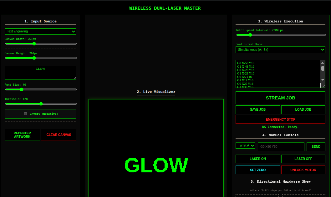
well there is not much coding to be done. you ll need python to installed on your computer, clone the repo and inside the repo folder create a venv environment ("python3 -m venv .venv") and do a pip install -r requirements.txt. it varies for different operating systems so you better off googling that for a better explanation. but basically you create a venv environment, activate it and install the dependencies which are only two esptool and mpremote. these are used to flash the firmware on the esp32. there are instructions on how to do that in the repo's README.md file in the quick start section. the code still have some bugs and can be better but in general it works. i have included AGENTS.md incase you wanna dig into it with your AI agent. (https://github.com/lebdroid/laser-project).
Lastly the Board
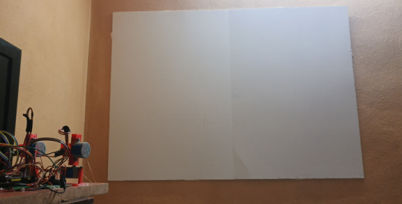
i used a white cardboard and sprayed it with a glow in the dark spray and used mounting tape to stick on the wall. well good luck and have fun!