Wireless Servo Control With Arduino
by keysdapp in Circuits > Arduino
217 Views, 1 Favorites, 0 Comments
Wireless Servo Control With Arduino
NOTE: Some sections of this Instructable contain code blocks that don't load properly until you scroll to the end of the page. Try doing that and scrolling back up before reading it.
In this Instructable, we’ll be showing you how to set up a basic wireless communication system using an Arduino (Uno or Nano) and the nRF24L01 (henceforth called RF24) transceiver modules. When we first tried to work with these modules, we ran into several challenges with wiring and coding, as many tutorials didn’t explain the process clearly and in depth. That’s why we decided to share my experience and make it easier for you! Most guides focus on complex setups, but in this tutorial, we’ll keep it simple by showing you how to:
- Wire the RF24 module to your Arduino board correctly.
- Code a basic transmitter and receiver system using the RF24 library.
- Enable wireless communication between two Arduino boards for sending and receiving data.
- Add in data sources and destinations, such as a joystick and servos.
By the end of this Instructable, you'll be able to set up a system to send a simple message and be able to control servos remotely. Let’s dive in!
Supplies

- 2x Arduino boards (UNO or NANO)
- 2x nRF24L01 Bluetooth Modules
- Jumper wires (M to F)
- Computer with Arduino IDE installed
- 2 Micro Servos
- 2 Potentiometers
Wiring the RF24 Transmitter and Receiver
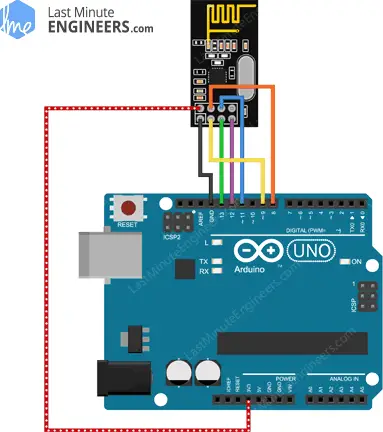
Here is a circuit diagram that shows how to properly wire the RF24. The same wiring is used for both the transmitter and receiver.
Wiring the Radios
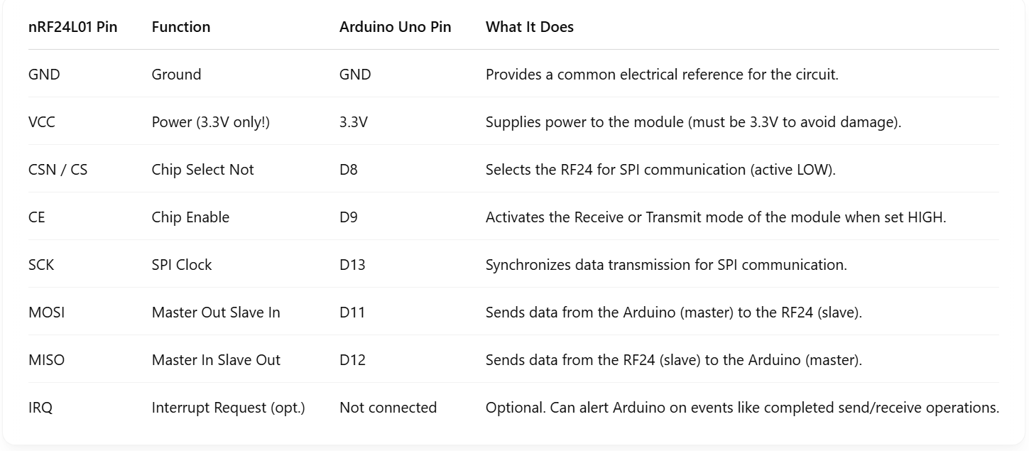
Here is a table that explains how to wire you RF24 transmitter and receiver. The table explains where each RF24 pin connects to the Arduino pins. It also explains the function of each pin and explains what it does.
Wiring Potentiometers to Transmitter
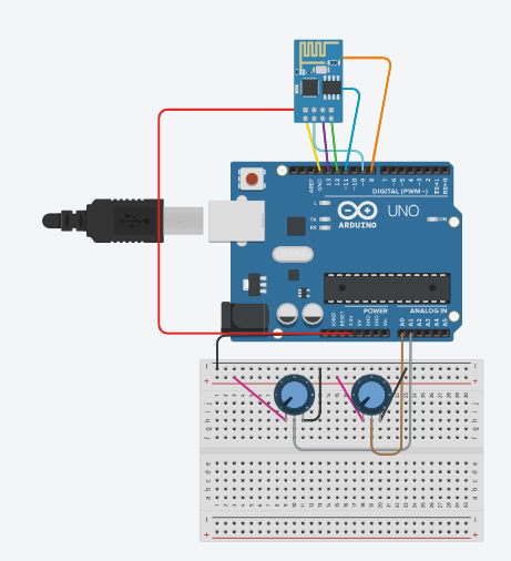
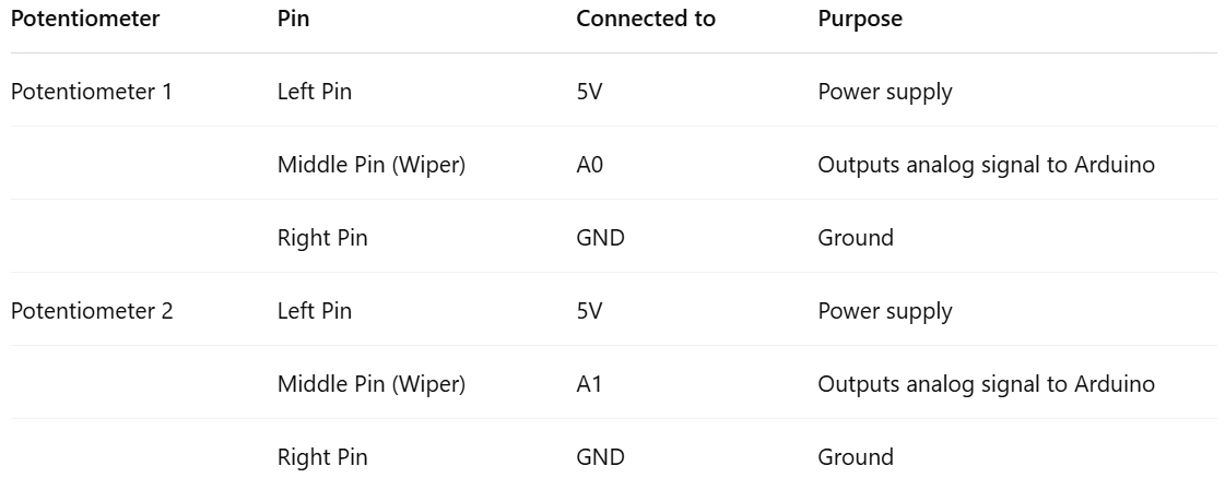
Here is a wiring diagram of how to wire potentiometers to the arduino using your transmitter RF24. On the right is a table that explains where to wire each potentiometer pin and explains what each pin is used for. To wire the RF24 follow steps 1 and 2.
Wiring Servos to Receiver
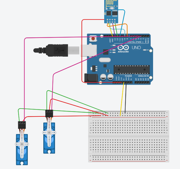
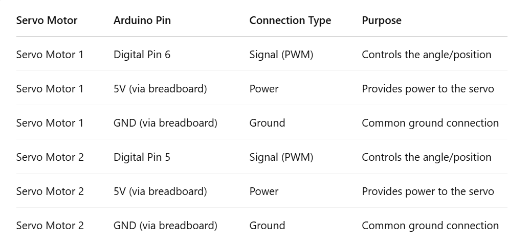
Here is a diagram of how to wire potentiometers to the arduino using your receiver RF24. On the right is a table that explains how to wire the servo and which pins to wire it to. To wire the RF24, follow steps 1 and 2.
Programming a Hello World Transmitter
This code uses the 1.4.11 version of the RF24 library. It is unlikely that the code will change much in future updates, so using a different version will rarely be a source of issues, but is still something to keep in mind.
Transmitter
First, let’s program the transmitter. We’ll need to import the necessary packages first:
Next, we can set our pin and address constants:
The CE_PIN and CSN_PIN constants correspond to the digital pins you plugged the RF24 into. The ADDR constant must remain the same on the receiver for the devices to talk to each other.
Now we can instantiate and set up our radio:
The setPALevel method is optional, but during testing we found that we didn’t need the range provided by the high-power mode.
Next, let’s finish the Hello World example by sending a message every second:
Receiver
The receiver setup is very similar:
The only difference is that you need to open a reading pipe and start to listen instead of opening a writing pipe and stop listening. We also set up the Serial so that we can see the data that is being received.
As for receiving the message and printing it out, the library also makes it very easy:
And just like that, we have our two Arduinos communicating wirelessly!
Programming
Transmitter
Adding a data source (here, a joystick) is ridiculously easy. A joystick is just two potentiometers so we need to add their pins to the constants:
Then we can set them to input in the setup:
In order to control the servos properly, we need to map the joystick outputs (which range from 0-1023) to an angle (0-179):
We also store that data in an array so we can send it over the radio:
Receiver
The receiver is a tiny bit trickier, since we need the Servo library (we used version 1.2.2):
And then all we need to do is write the data to the servos:
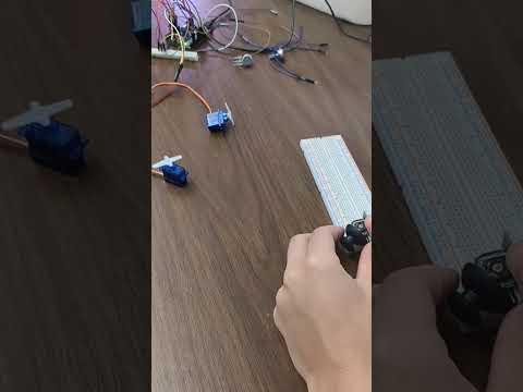
Video Demonstration

Here is a video of our working wireless servo control. In the video we use a joystick, however the joystick works the same way as the potentiometers would. When the joystick moves up and down it controls one servo, when it moves side to side, it controls the other servo. With the potentiometers, one potentiometer controls one servo, the other potentiometer controls the other servo.