Wooden Play Board for Volleyball Rotations: Bombardino Board
by volleybll in Workshop > Woodworking
112 Views, 2 Favorites, 0 Comments
Wooden Play Board for Volleyball Rotations: Bombardino Board
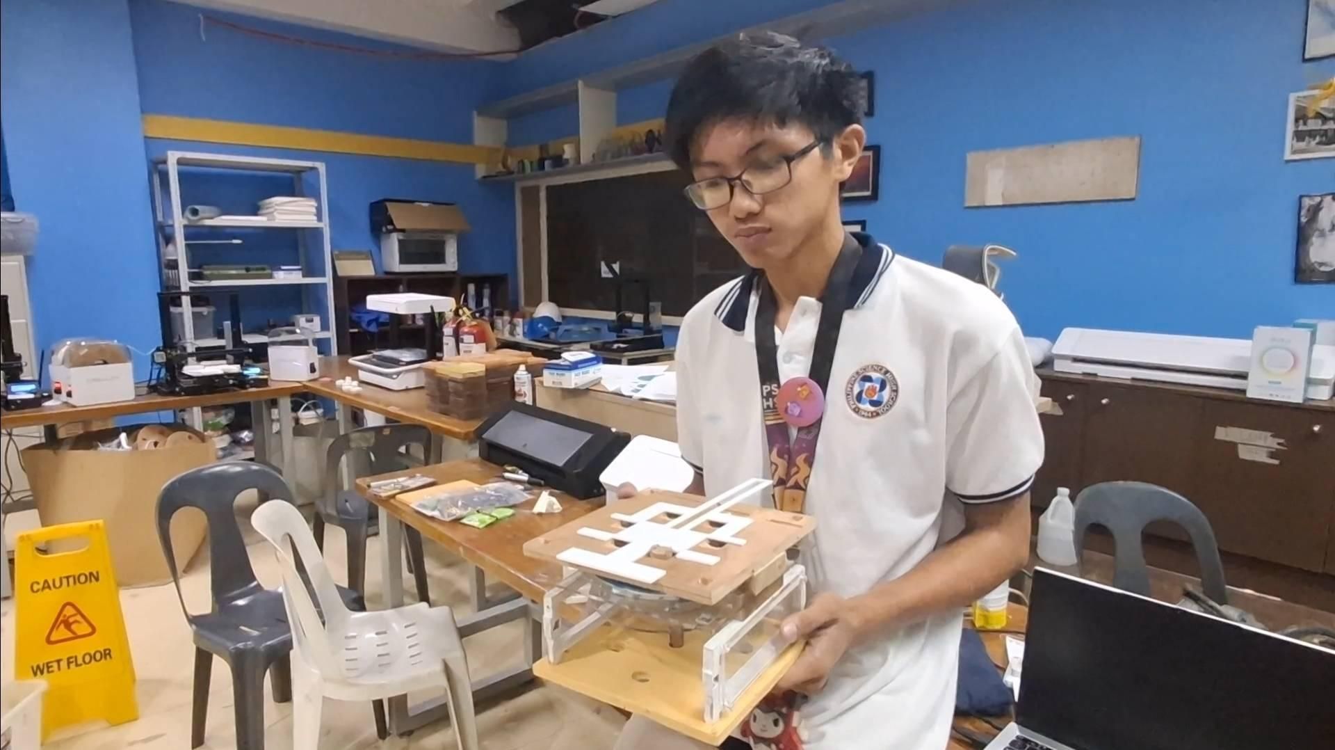
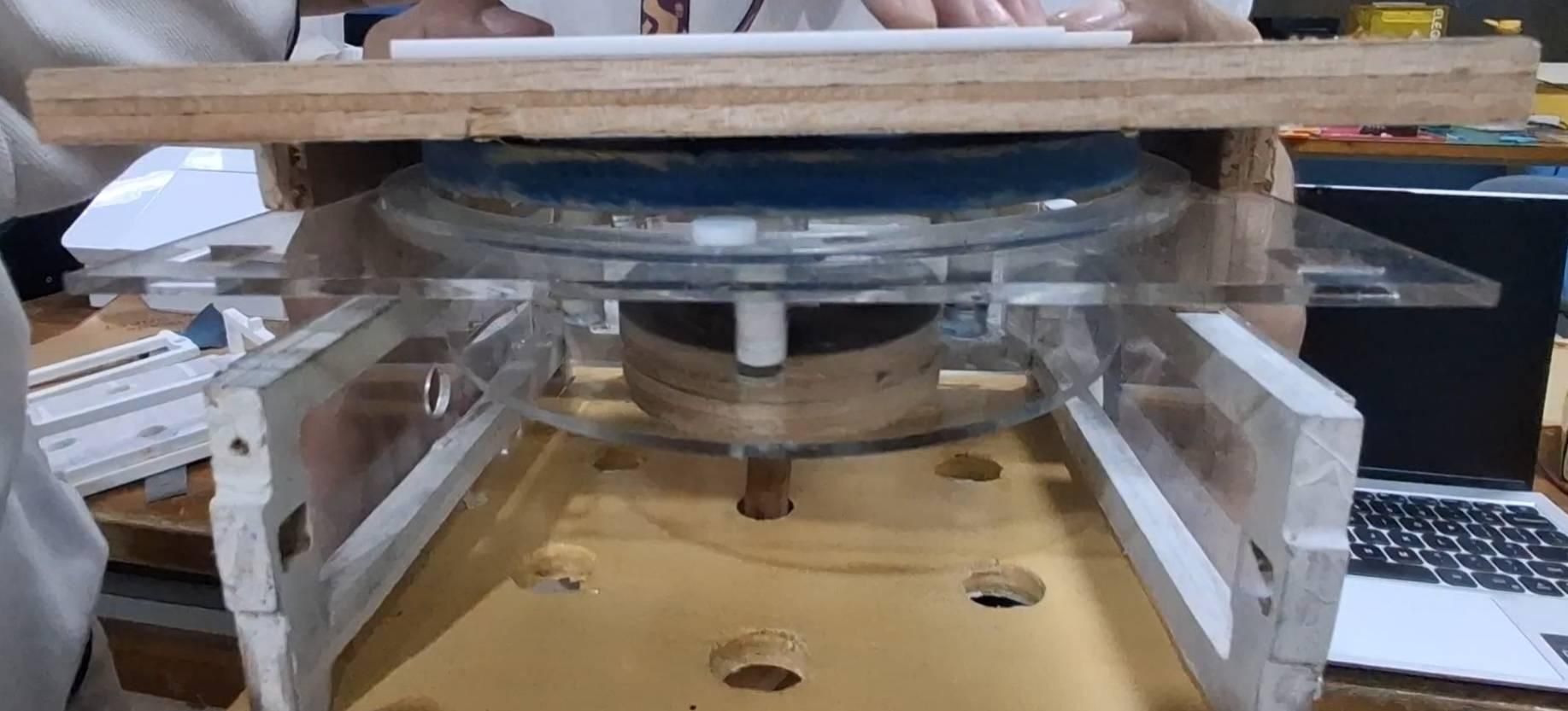
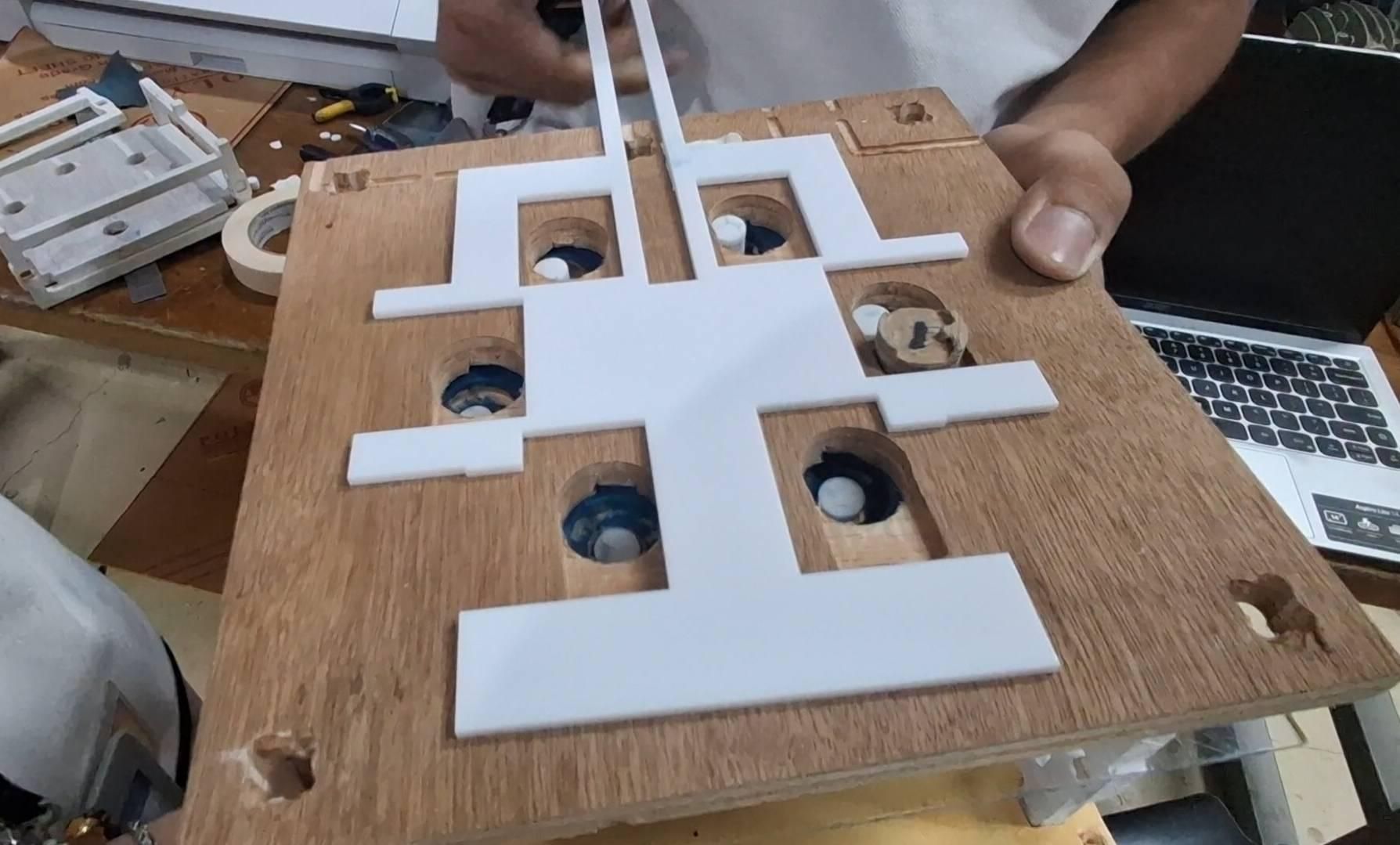
Hi volleyball fans!
Every sport has some kind of trademark playable outside of playing the sport.
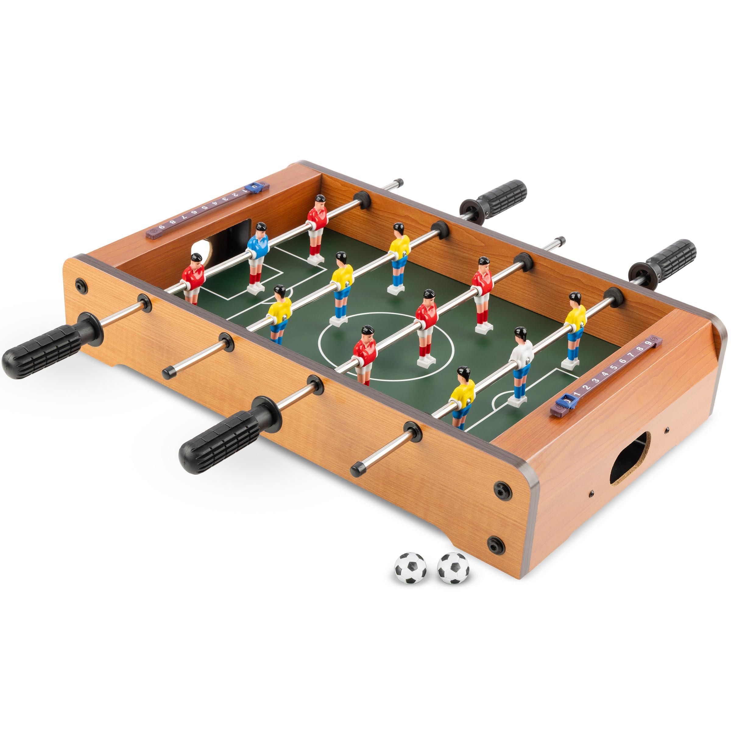
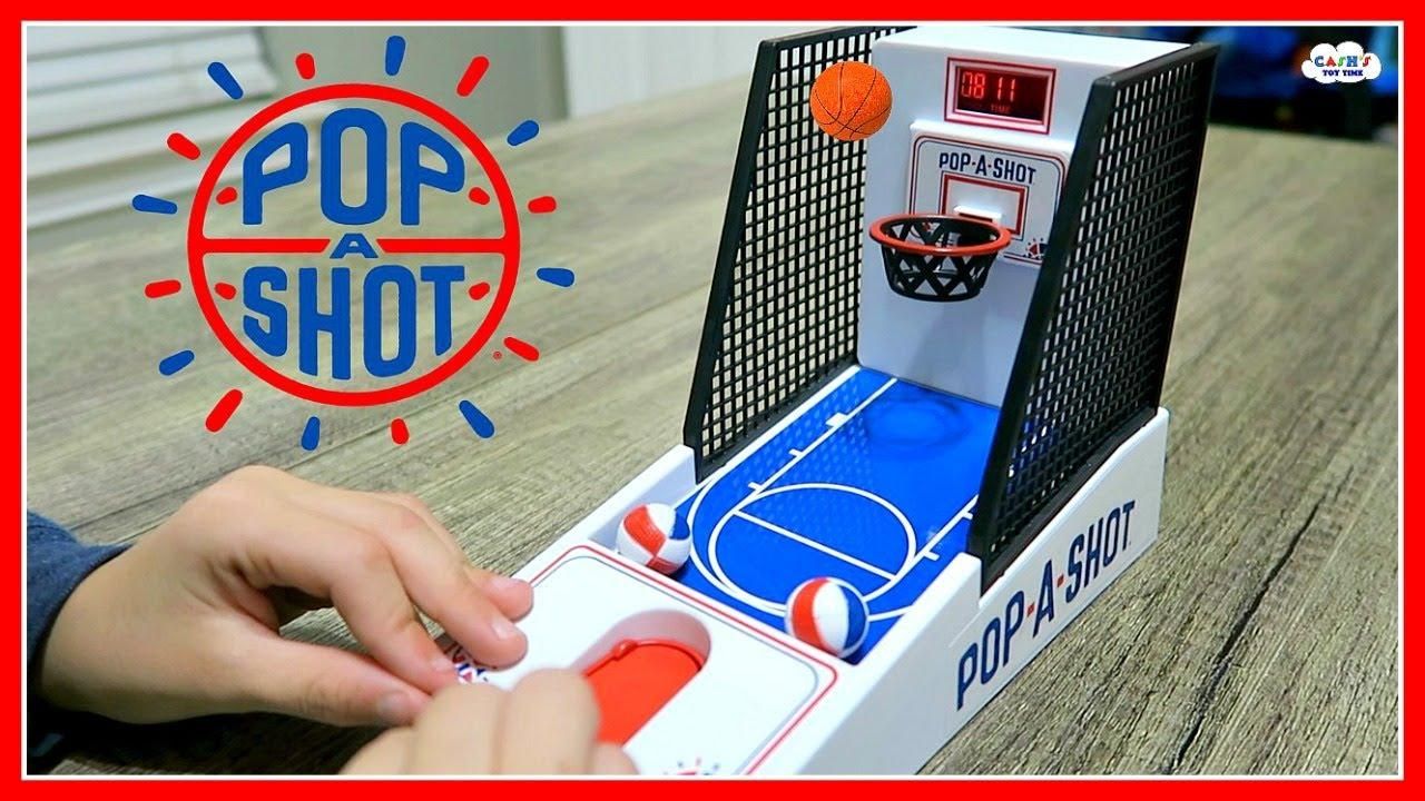
Football has foosball, basketball has mini hoop launchers. Well, what about us?
I introduce to you the first version of our Bombardino Board for Volleyball!
This original Chindōgu invention lets you feel the rotation of six players with a wooden board.
Supplies
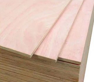
Each woodcutting file will fit in the standard plywood size of 300x300x10mm. You will need at least five standard pieces of plywood, or any type of lightweight wood.
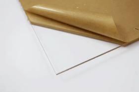
The lasercutting files will fit in one acryllic board of size 500x300mm with a required thickness of 3mm. The acryllic board may be any color of your choice.
Understanding the Design
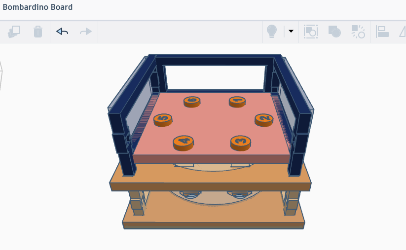
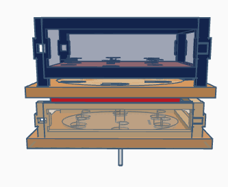
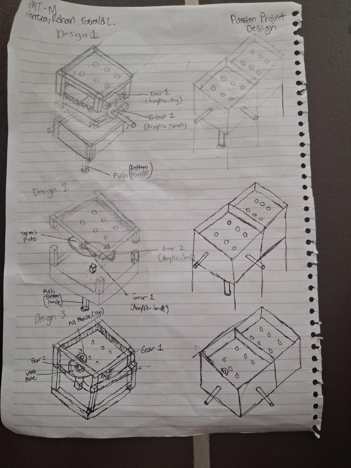
The design incorporates several parts that come together to simulate the rotation of six chips in a circle.
Each of these chips (labeled 1 through 6) represents a specific player/position in a volleyball team. There are six players, and consequently six rotations. The main struggle in the design is to allow these chips to rotate without being seen or touched, which creates a sense of one "locked" rotation to be displayed as a volleyball memorabilia.
My timeline for creating the project went as follows:
Week 1 - Designing the project through paper and TinkerCad, simulating mechanisms
Week 2 - Transferring pieces to VCarve and InkScape, preparing .pdf and .tap files
Week 3 - CNC woodcutting and lasercutting, making safe adjustments and micro-improvements to the design
Week 4 - Piece assembly and adjustment of minor pieces
Downloading the CNC and Lasercutting Files
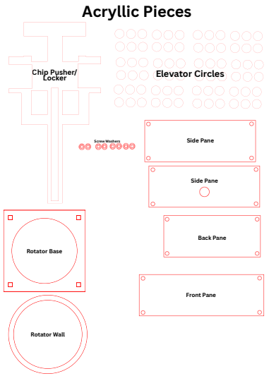
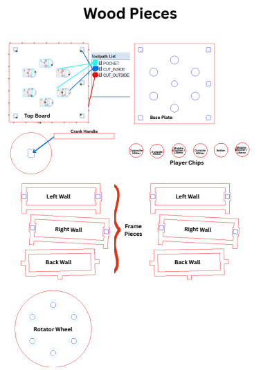
Before we assemble the board, we have to download our gcode files for woodcutting and pdf files for lasercutting!
Files in .pdf indicate that they use acryllic and a lasercutting machine.
Files in .tap indicate that they use wood and a CNC woodcutting machine.
Cutting the CNC Wooden Pieces
Open your gcode files on the machine desktop through USB connection. Ensure proper calibration of the machine, wear protective equipment, and handle the machine under supervision. Remove wooden pieces from the plywood gently with mallet and chisel. Sand down piecs but maintain friction fit if applicable.
Cutting the Lasercut Acryllic Pieces
Open your .pdf files on the machine desktop through USB connection. Ensure the machine exhaust is on before cutting. Check the snug fit of all necessary corners within the board before running the machine under supervision.
Making the Frame Walls
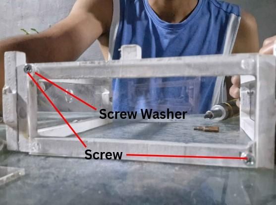


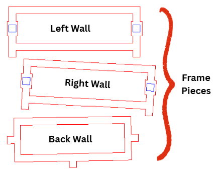
Connect your friction-fittable frame pieces. The back wall's tabs fit into either slot of both the left wall and right wall. This creates the frame of the base plate.
Optional Step: Take your lasercut panes and screw washers for the frame walls. Take 9/32 inch or smaller screws with lengths not exceeding 3/4 of an inch. These create a more displayable look while making the bottom area still visible.
To connect your panes, align the corners of a pane to its corresponding frame wall. Take one screw washer and insert a screw going through the washer and into a hole on the corner of the pane. Screw this in with a screwdriver or drill (but be careful-- it might split the wood). Repeat for all corners and all panes.
Assembling the Base Plate
.png)
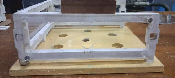
Attach the bottom tabs of the assembled frame walls onto the base plate in proper orientation. They should fit tightly.
Assembling the Rotator Plate
.png)
.png)
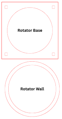
The rotator plate must be understood as the surface that supports the rotator wheel. This consists of the rotator wall, which prevents the rotator wheel from moving, and the rotator base, where the rotator wheel rests on.
Apply superglue to the rotator wall and glue it carefully on the rotator base so their centers match. Part of the rotator base surface should be exposed on both the inside and outside of the wall.
Assembling the Elevator Plate
.jpg)
.png)
The elevator plate is your control wheel that dictates the movement of the chips outside of view. It is named by its function to elevate the chips onto the top plate before locking them into position. This is done by properly placed elevator circles that will fit into the hole of the rotator wheel. Its other function is to rotate the wheel when fit slightly below maximum height by acting as a key into the rotator wheel and spinning it from the bottom.
Take the solid acryllic circle cut out within the rotator wall. This will be the elevator plate.
Apply superglue on the engraved circles on the elevator plate. Stick one elevator circle on each position. Attempt to fit them into the rotator wheel. These should fit nicely without friction.
Stack another elevator circle on each glued circle. Align them to each other as precisely as possible as this will affect the fit of the rotator wheel. Repeat this process until there are exactly twelve elevator circles stacked.
Note: If they eventually do not fit due to alignment errors, you may sand the holes of the rotator wheel wider. Alternatively, wet the superglue and remove it, then re-glue them in place.
Finally, glue the circular wooden piece of the crank handle to the bottom of the elevator plate as shown in the image.
Fitting the Elevator Plate to the Base
.png)
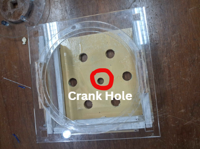

The elevator plate is connected to the base plate via the crank handle.
Create the crank handle by fitting the two pieces as shown in the image. This enlargens the surface area for the user to use less force when rotating the wheel. The rectangular piece comes from below the base plate.
This creates the controllable piece that combines the elevator plate and the crank handle. Fit this piece by inserting the crank handle into the crank hole from the top. Test the crank handles rotation and motion by turning and pushing the crank handle from below the base plate. This may require you to carry the whole base plate up.
Optional: If you feel that the friction-fit is not tight enough, you may apply wood glue to the friction-fit area of the crank handle to lock the handle as one piece. However, this prevents it from being disassembled in case of adjustments.
Recommendations: The crank handle can work no matter the length, as long as it still sticks out the bottom when the base is carried. Handsaw the rectangular crank handle piece to shorter length so that the base plate can rest on a table.
Mounting the Rotator Wheel
.png)
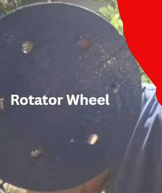
Take your wooden rotator wheel and drop it on the inner part of the rotator walls. Test the smoothness of its rotation so that it smoothly rotates along the acryllic without any other movement. For smoother rotation, sand the sides of the rotator wheel up to 220-grit or higher.
Optional: Apply a varnish coat around the rotator wheel. Sand lighty to flatten raised grain and repeat varnish coating until the perimeter of the wheel is silky-smooth to ease rotation.
Assembling the Top Board
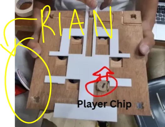
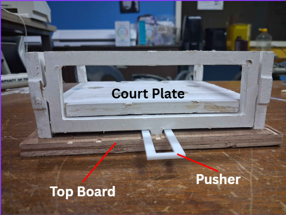
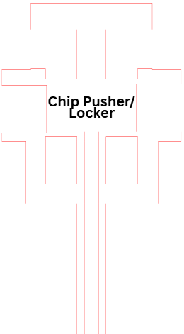
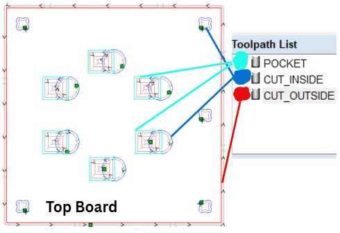
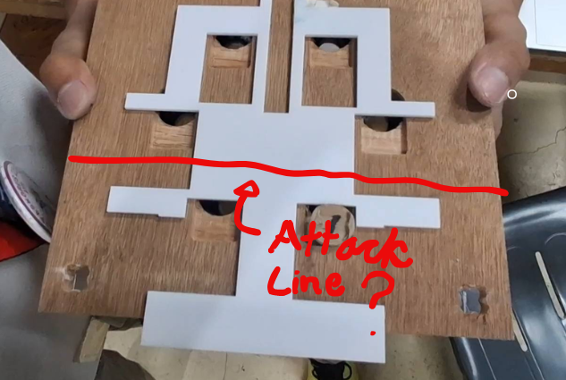
The top board must be assembled with another key part in mind: The Pusher. The Pusher pushes the player chips to let them fall into the holes in the Top Board as shown in the image. The chips come back up and are locked into place by pulling the Pusher or pushing it from the other side.
Position the pusher so that all six holes are exposed but enclosed by the pusher as shown in the image.
Connect the frame walls to each other and to the top board in unison, in the exact same manner as Step 6. Sandwich the long end of the pusher into the middle tab of the back frame wall. Leave some clearance between the top board and the wall bottom for the pusher to move.
The pusher should move smoothly forward and backward. Lightly sand (320+ grit) the surface of the top board for better movement.
Putting It All Together
.png)
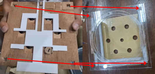
The only thing left to do is to connect the top board to the rotator plate.
Place some connector pieces on each of the four corners as shown inthe image and apply adhesives like superglue and woodglue to keep everything in place. See the picture for the final assembly!
Finishing Up - Make It Yours
.jpg)
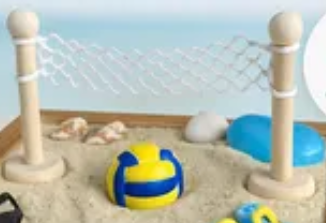
Another name I considered for this project was "Volleymaker". This project should be easily customizable for anyone to their best ability, so I only focused on the mechanical part of it. That said -- make it yours!
Paint your parts and pieces to any color. Volleyball courts come in varieties of shades!
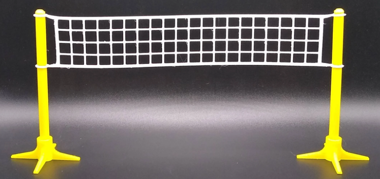
Add mini balls, paint an attack line, glue in your mini volleyball net. Memorabilia comes from stories, or alternatively, the work that went behind it. Good luck!