XR-4: DIY, Low-cost 3D-Printed Rover Platform
by Salman Naveed in Circuits > Robots
669 Views, 9 Favorites, 0 Comments
XR-4: DIY, Low-cost 3D-Printed Rover Platform
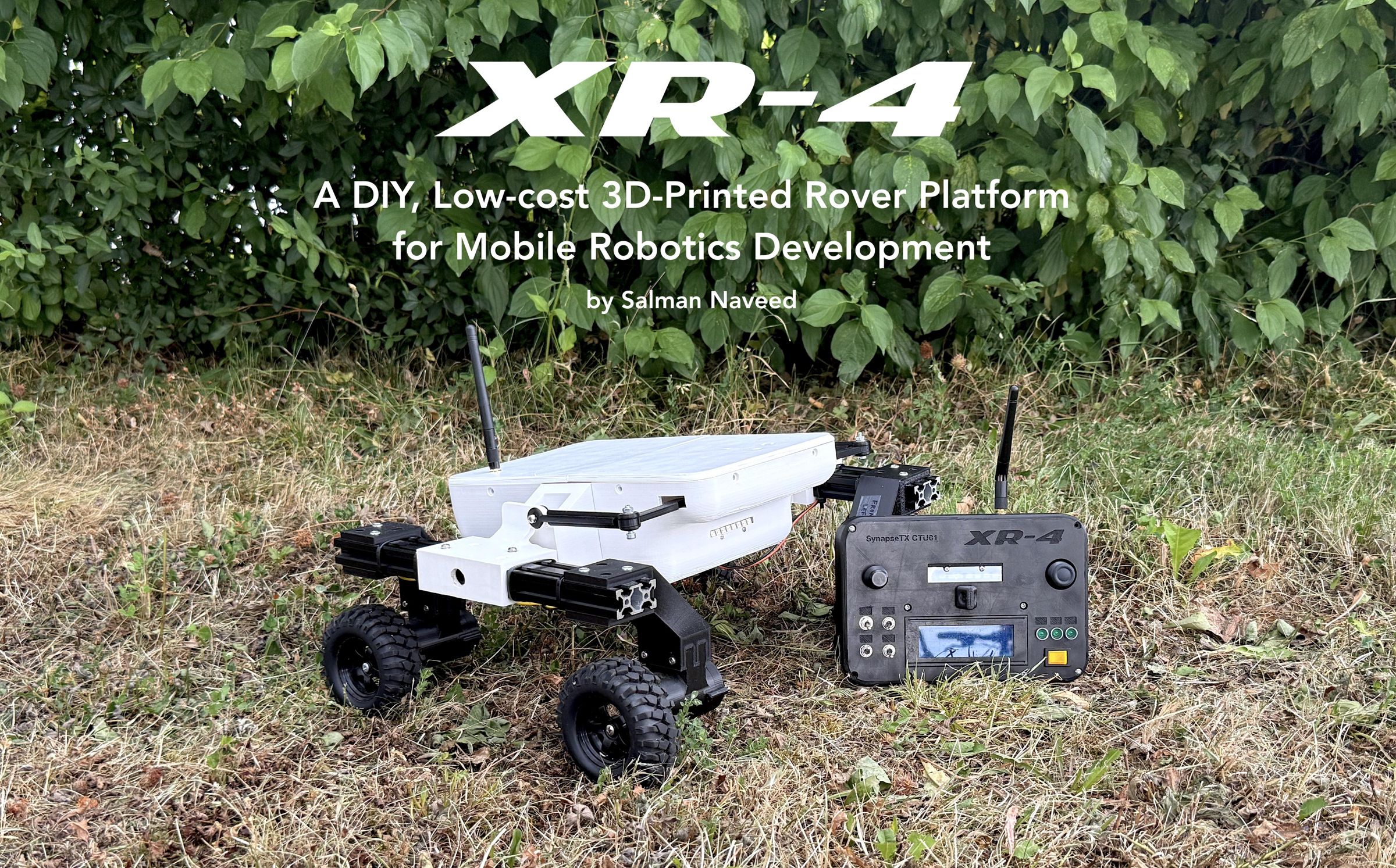
Are you a robotics or engineering student, hobbyist or enthusiast? Or do you want to work on relatively advanced projects related to mobile robots, autonomous driving and navigation? And do you want to do it without having the budget of a government-funded institution or a cash-flush university lab?
If yes, then the XR-4 (eXperimental Rover - 4) might just be the perfect project for you. It is an affordable, 3D-printed rover inspired by the LeoRover (made by fictionlab of Poland) and is intended to serve as a platform for Autonomous Mobile Robotics-related work - on a budget.
As makers, hobbyists and students of engineering, it is sometimes very difficult to work on advanced personal projects due to financial limitations, because specialized hardware is prohibitively expensive and therefore, out of the reach of ordinary people.
It was with this goal in mind, and as a personal challenge, that I took up the task of developing an affordable platform which could fulfill this requirement. It had to be relatively cheap, require no specialized components and tooling, must be totally upgradable, had to be a tinkerer's toy and - most important of all - had to be fun to build.
I also wanted to use a lot of the components from my parts bins, as a result, you might find some lack of standardization that might be found in a factory-produced product since I had to improvise or make do with what I had or could find in discarded electronics and electromechanical products. This also helped to lower the overall costs.
Some facts about this project
The rover uses a 4WD drivetrain with 12V brushed DC motors running at 100RPM, standard LiPo batteries, and a differential drive steering mechanism. The suspension is of Rocker Differencing Kinematic type, a variant of the Rocker-Bogie used by NASA on their Mars rovers. It uses ESP32 (WROOM-32U) microcontrollers both as the On-Board Computer (OBC), a low-level controller to run the motors, manage communications, execute commands, read sensors and as the "remote controller" known as the CTU (Control & Telemetry Unit). The CTU is the handheld control unit that the operator will use to control the rover and monitor its "vital signs" on a 20x4 LCD screen.
The electronics are custom-made, and at the moment are only built up on regular Veroboard/perfboard.
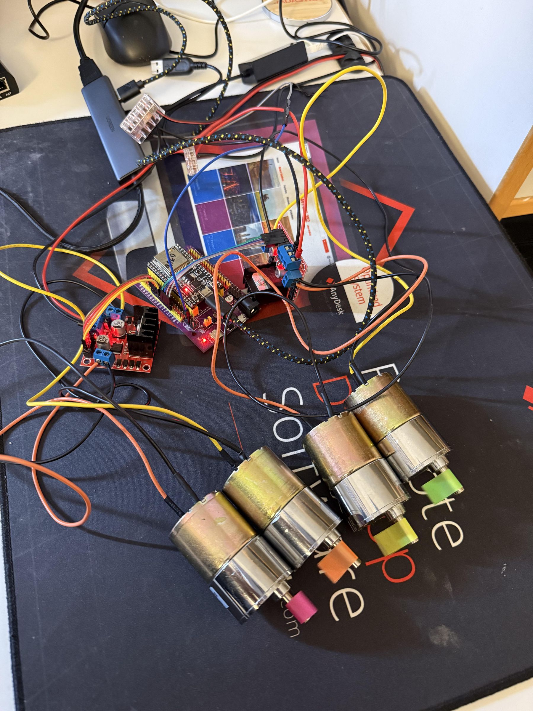
The drive and steering are relatively simple, with the motors being controlled by 2x L298N motor drivers.
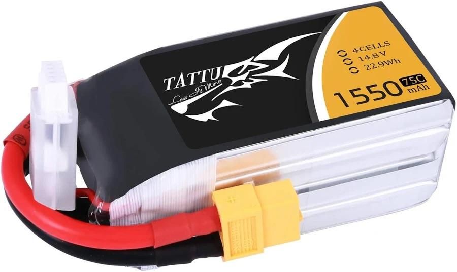
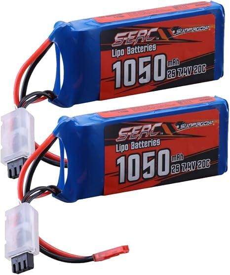
The rover uses a 4S 1550mAh Li-Po battery since that is something I had with me from a previous project. Ideally, I would want a larger battery but this is sufficient for now. The CTU uses a 2S 1050 mAh battery and powers the CTU's electronics through a buck converter which steps down the voltage to 5V.
Disclaimer
- Even though I consider this project to be well-documented, please understand that it was built over a long period of time and therefore, some aspects of it might not be as well documented as others
- I was iterating very quickly during the design phase, therefore, the designs (specially on paper) would not necessarily match with what you see
- I am not adding a detailed explanation of the code because it is very extensive and because it contains a lot of helpful comments and README documents
- This project is not for absolute beginners - it would be ideal if you are an engineer or a student with a reasonable understanding of the technical topics relevant to this project, as well as practical experience in some of the areas and in usage of the tools (if you are a beginner, then Instructables is a great place to start and you should begin with some basic projects before jumping to this)
Supplies

Tools and Equipment
- a 3D printer with a print area of up to 330 x 240 x 300 mm (I used the Ultimaker S3 & S5 because those were the only ones available to me)
- Soldering iron
- multimeter
- battery chargers (for LiPo)
- lab power supply
- Wire stripper, wire cutter, crimping pliers
- Screwdrivers and Allen key set
Parts and Components
(in no particular order)
Control & Telemetry Unit (Remote Controller)
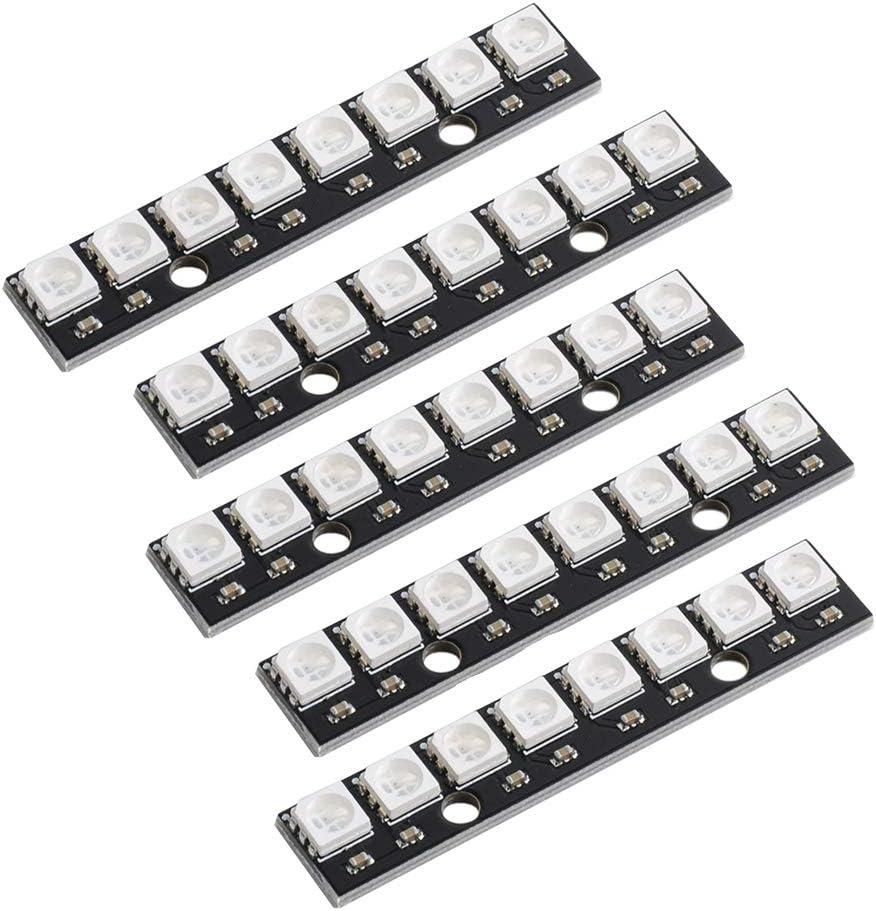
- WS2812B 8-bit RGB LED Strips (1 x)
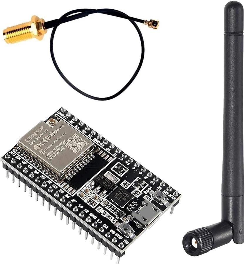
- ESP32-WROOM-32U Dev Modules (with external antenna)
- Li-Po Battery 2S (1050 mAh)
- Toggle switches (4x)
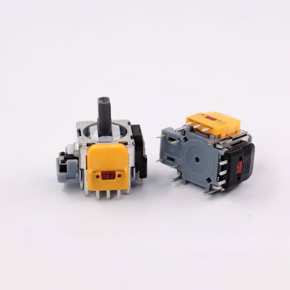
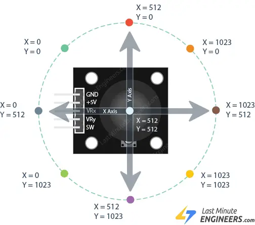
- Hall-Effect Joystick (1x) (Amazon)
- Rotary encoder module
- 20 x 4 LCD
- I2C backpack for LCD
- Power switch
- PS5 Hall Effect Joystick Compatible Breakout Board (Github) (can be ordered via PCBWay)
Rover Structure & Electronics
- Li-Po Battery 4S (I already had a 1550mAh one, future upgrade needed)
- ESP32-WROOM-32U Dev Module (with external antenna)
- WS2812B 8-bit RGB LED Strips (2x)
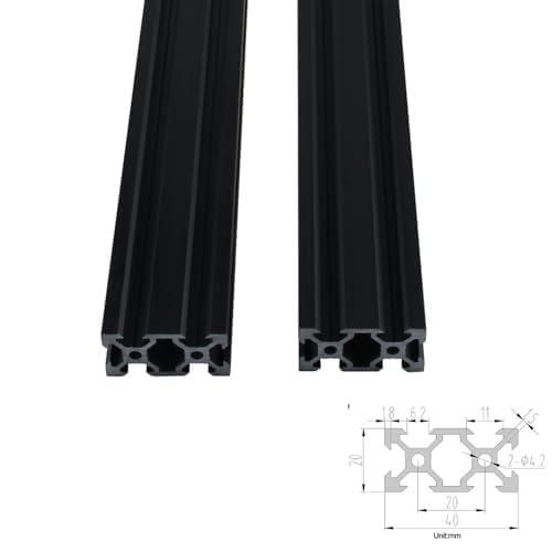
- 600mm V-Slot 2040 Aluminum Extrusion Profile (2x) (Amazon)
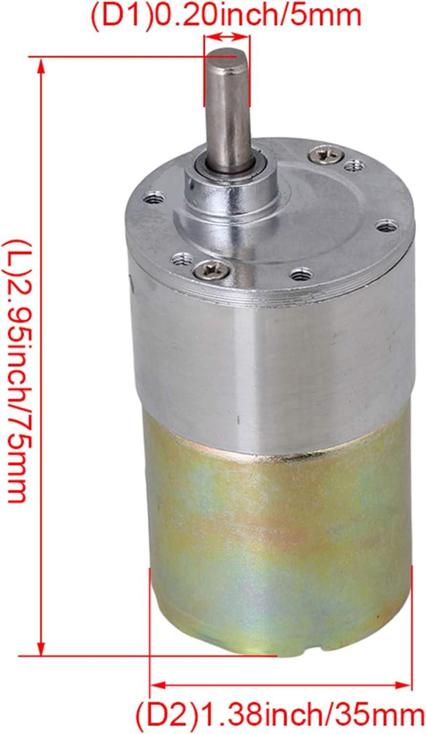
- 12V DC 100 RPM Electric Motor (4x) (Amazon)
- MARQUARDT 18056102 DPST Power Switch (1x) (Bürklin) (I am just adding this for completeness, you can use any switch you want, it should only be rated for approx. 24V and upto 5A DC)
- Wires and Cables (of appropriate gauges, mentioned in the Power & Electronics section)
- Perfboard/Veroboard
- Passive components (Capacitors, resistors)
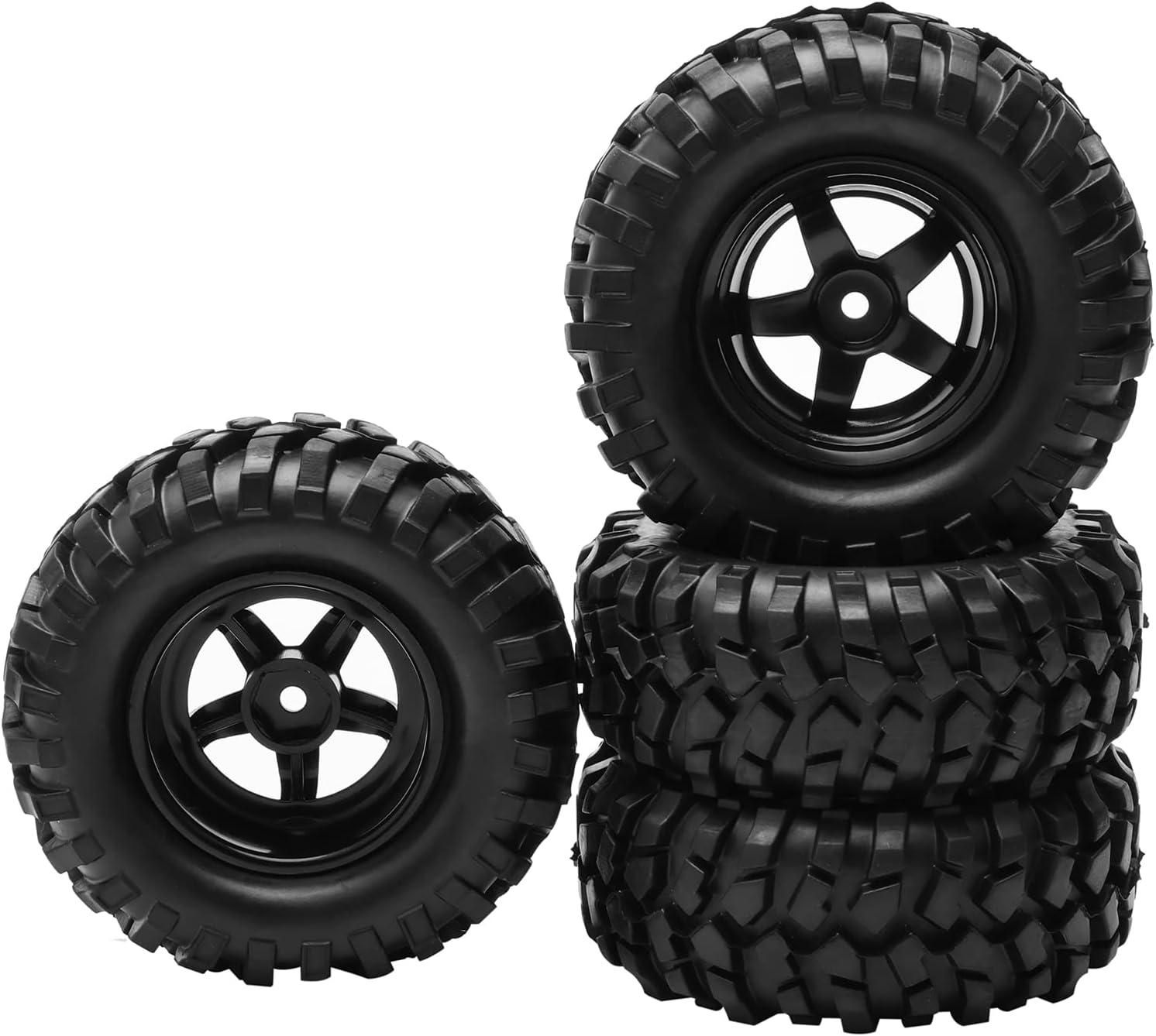
- RC 1:10 Buggy Rubber Tyres 5 Spoke (4x) (Amazon)
- Screws (details in the relevant sections below)
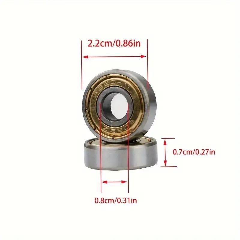
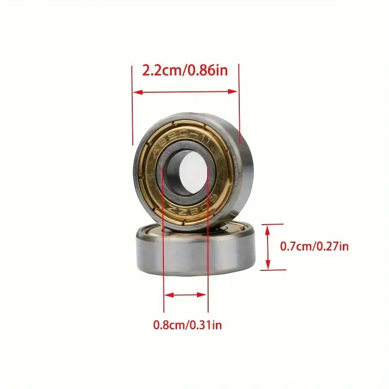
- 608RS Skater Bearings (2x)
CAD
All the CAD files required for this project are attached as .step files in the relevant sections. For e.g. the CAD files for the motor mounts and suspension components is available in the Suspension section and so on.
Concept & Inspiration

.jpeg)
I have always been inspired by space rovers such as the ones built by NASA, ESA and other space agencies. There are several robotics companies which make rover platforms too - for research and testing. And these rovers have always gotten me like:
"I've gotta get me one of those".
-Commissioner Gordon, Batman Begins (2005)
With this in mind, I had made several attempts at coming up with a conceptual design. Research about this topic, my own experience with 3D printed parts and an awareness of the limitations of my own design capabilities as well as the limitations of 3D printed parts had shown that a rover with a true Rocker-Bogie suspension might not be realizable.
Rocker-Bogie suspensions demand that the entire rocker and bogie assembly (the entire pivoting arm of the suspension) be connected to the rover's structure at just one point. This point has to be strong and robust, and must move freely and have zero radial play. This, along with the requirement of a differential to link up the two rocker-bogie arms with the chassis, made the entire endevour mechanically complex.
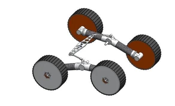
This drove me to go for the Rocker-Arm Suspension. Instead of having a secondary pivoting sub-frame (bogie) for multiple wheels, this suspension relies on main arms that pivot independently to absorb terrain irregularities.
By this time, I had also come across the LeoRover platform developed by fictionlab and I decided to broadly follow the design and size language from that in my original design. Obviously, since I would use PLA as my 3D printing material, a lot of the structural parts would have to be designed for strength and would naturally be bulky and have simple shapes and profiles.
Design & Development
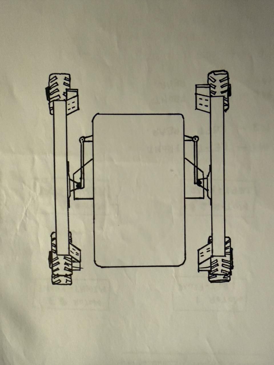
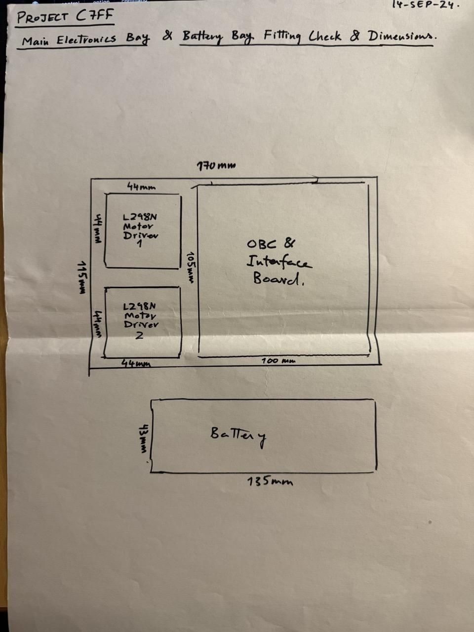
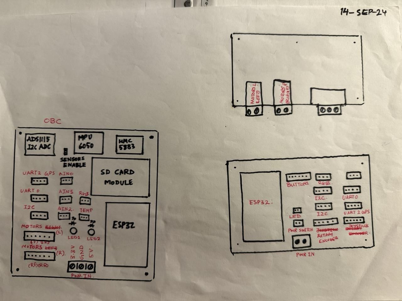
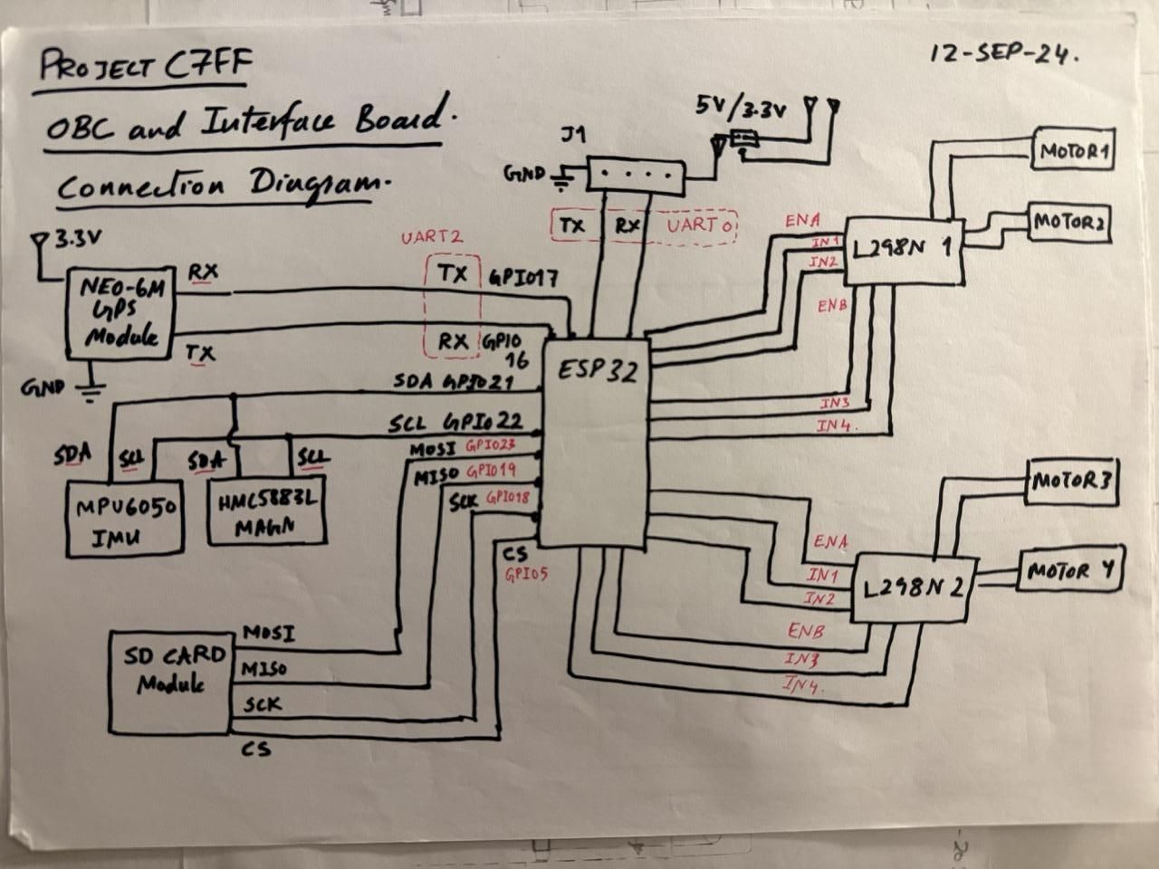

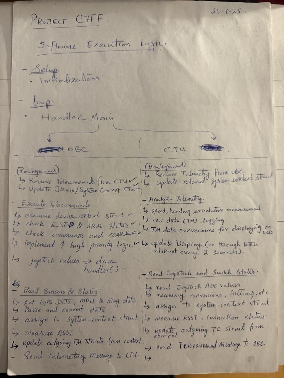
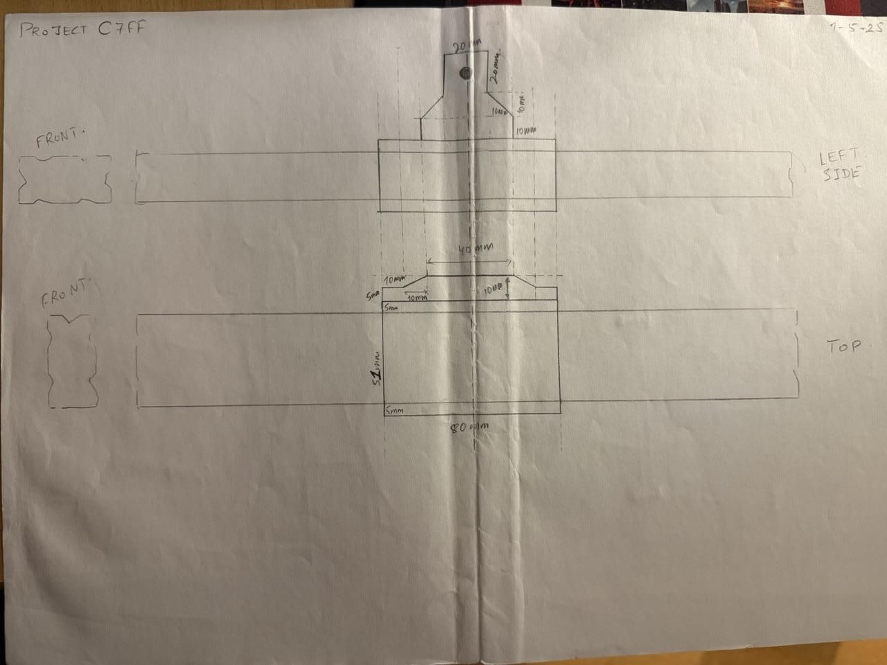
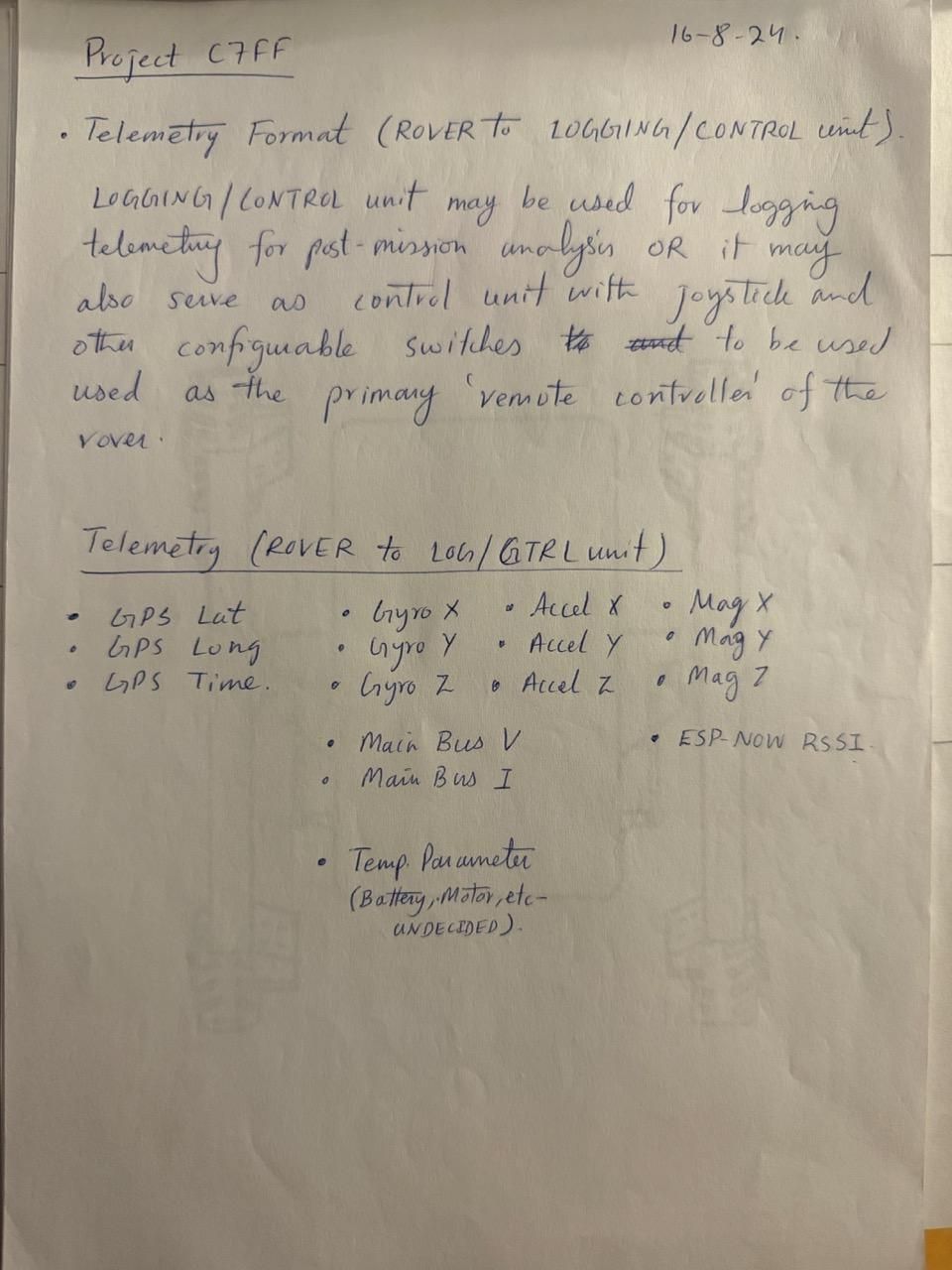
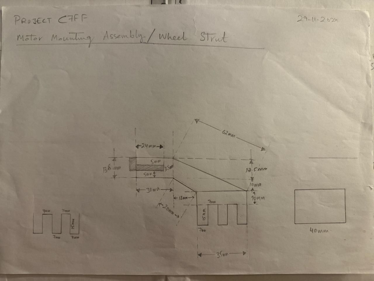
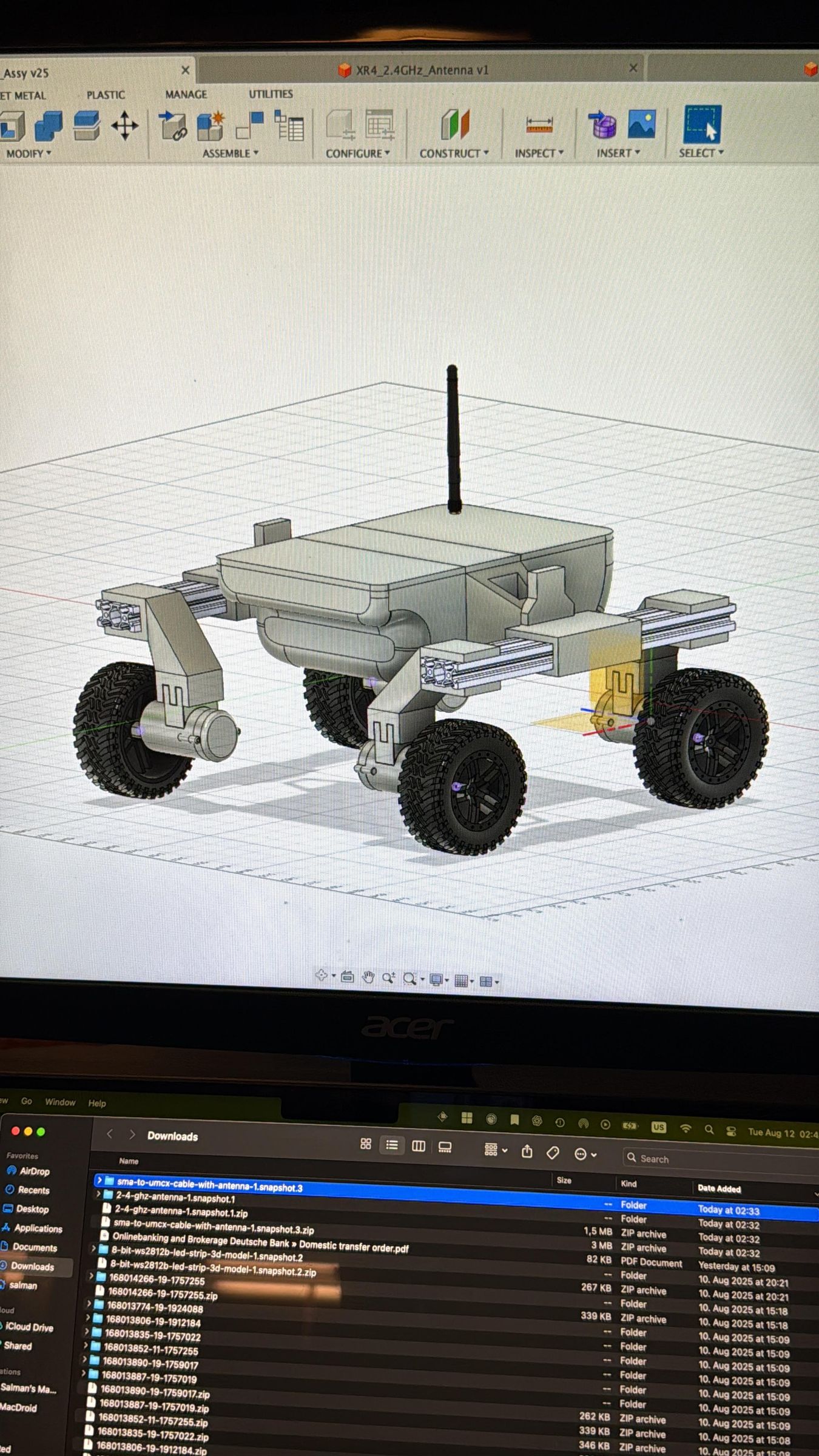
With the design inspiration and basic concept in mind, I got down to pencil and paper to sketch out how the rover would look like, how big it would be, etc etc. I made very rough, full sized sketches, some of which you can see in the pictures.
I also sketched out the architecture of the electronics and systems. The choices related to components, sensors, software were also constrained by whatever I had available. I did not want to procure a lot of parts and wanted to develop the project with the components I already had available.
The physical size of the rover was constrained by several factors, such as the length and weight of the available aluminum profiles that I would be using for the rocker arms (the use of Aluminum profiles was a given since I didn't want to 3D print such a huge part and PLA could not be guaranteed to maintain strength for long periods). There was also the matter of proportions, a poorly-proportioned structure would not be visually appealing - and appearance was an important factor for me.
For reasons of modularity, upgradeability and repairability (since this is a testbed after all and would require changes, modifications and even repairs), I decided on the three-part design with a front, center and rear section. The front and rear compartments would carry the electronics and power subsystems including the battery and the center section would primarily be a strong, solid structural member to which would be mounted the rocker arms.
Based on this, the dimensions of the front and rear compartments were dictated by the expected sizes of the electronics and power boards, the battery and some extra space for cable routing.
The documentation document attached in Step 7 (Rover_XR-4_Design_Documentation.pdf) contains all of the interfaces and pin mapping that I use (for both CTU and OBC), you can just use that as a reference while making a schematic (which I did not initially make due to the temporary nature of the veroboard-based electronics) or if you want to go my way - making a quick and dirty prototype board.
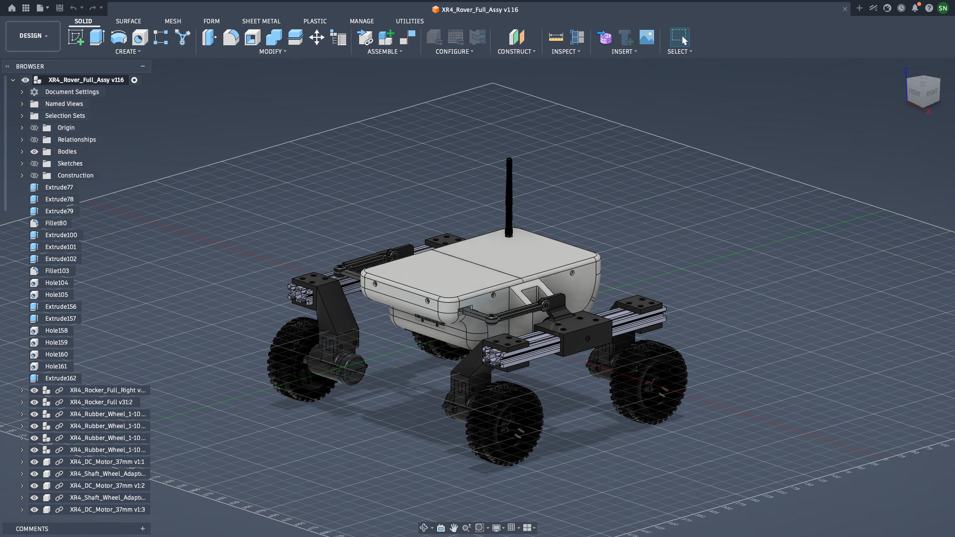
With the brainstorming and paper design phase complete, I moved to developing a CAD model in Autodesk Fusion. This was my first CAD project of such magnitude (since I am an embedded systems engineer and mostly work with VSCode, Altium, KiCAD, etc :)) and Fusion was a very reliable partner with a lot of resources online and very intuitive interface and options.
The CAD phase took a relatively long time - I was not working all the time and there were significant gaps in the work. However, I managed to complete it earlier this year. After several revisions in relatively minor aspects such as as screw holes, holes for wiring and cabling, redesigns of the rocker link arms and differential and discarding a complex and "fancy" mount for the OBC and PDB due to lack of space inside the rover.
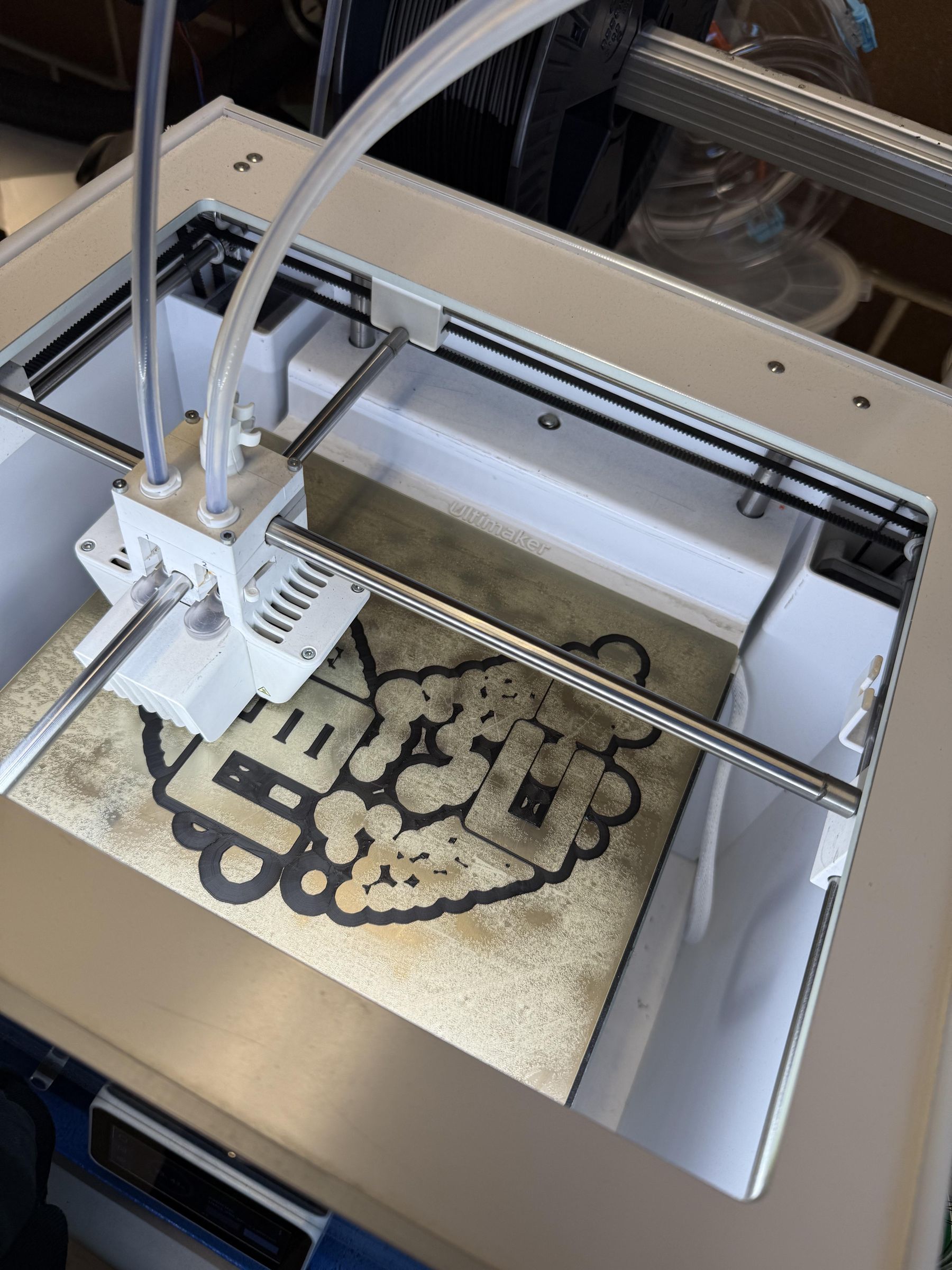
When I was confident that everything was in order, I went ahead with 3D printing all the parts. That endeavour also took around 10 days since I did it in a phased manner. Since I was using the 3D printing facility at my university, I did not want to put long duration prints in the middle of the day on weekdays since others would be prevented from using the printers then. Therefore, I printed on weekends and overnight on weekdays.
This reminds me, I will be forever grateful to the StudLab of the University of Stuttgart, run by the Fachschaft Elektrotechnik und Informationstechnik, it is an amazing facility which enabled me undertake this project.
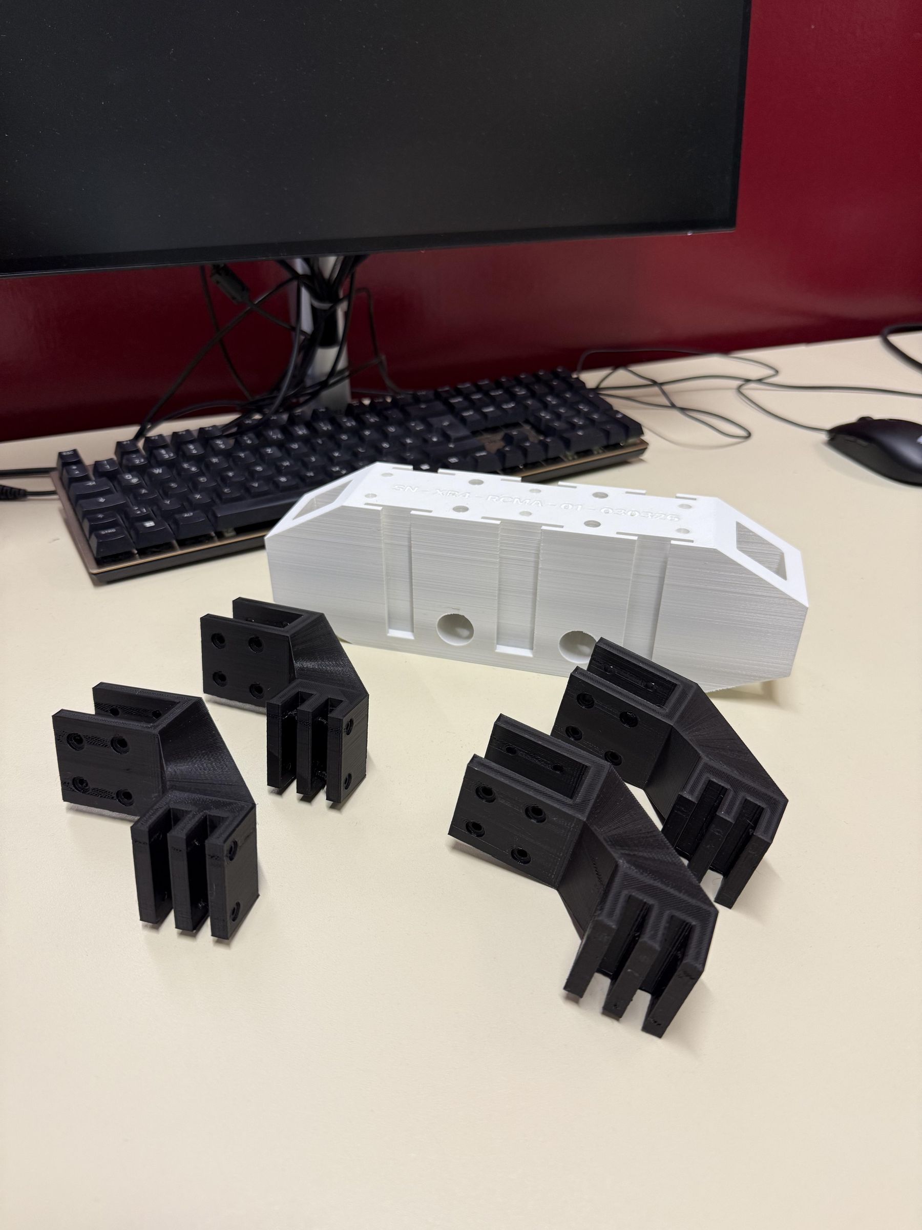
With the parts printed, it is time to go over the details of each of the parts to get an idea of what each part is before we move to the final assembly.
Suspension
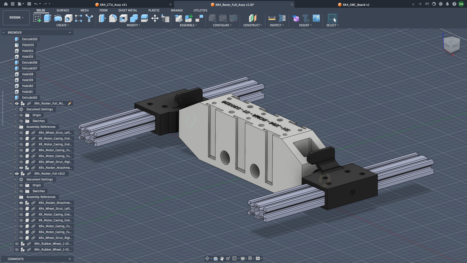
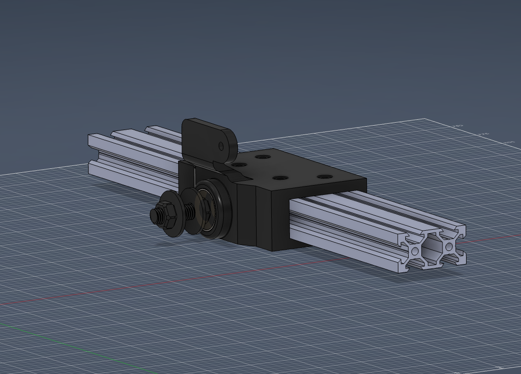
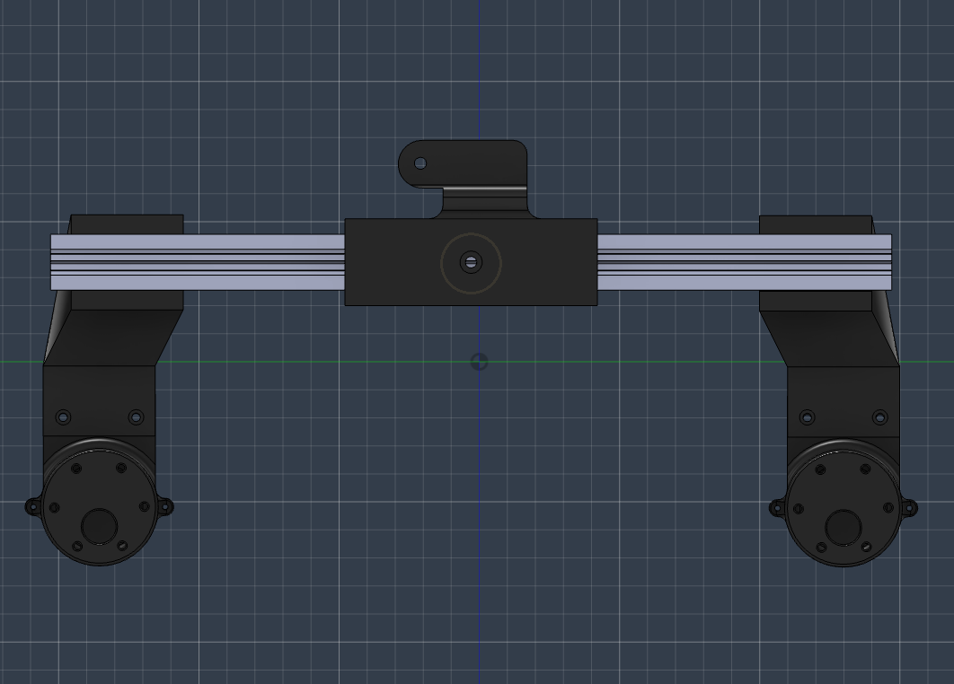
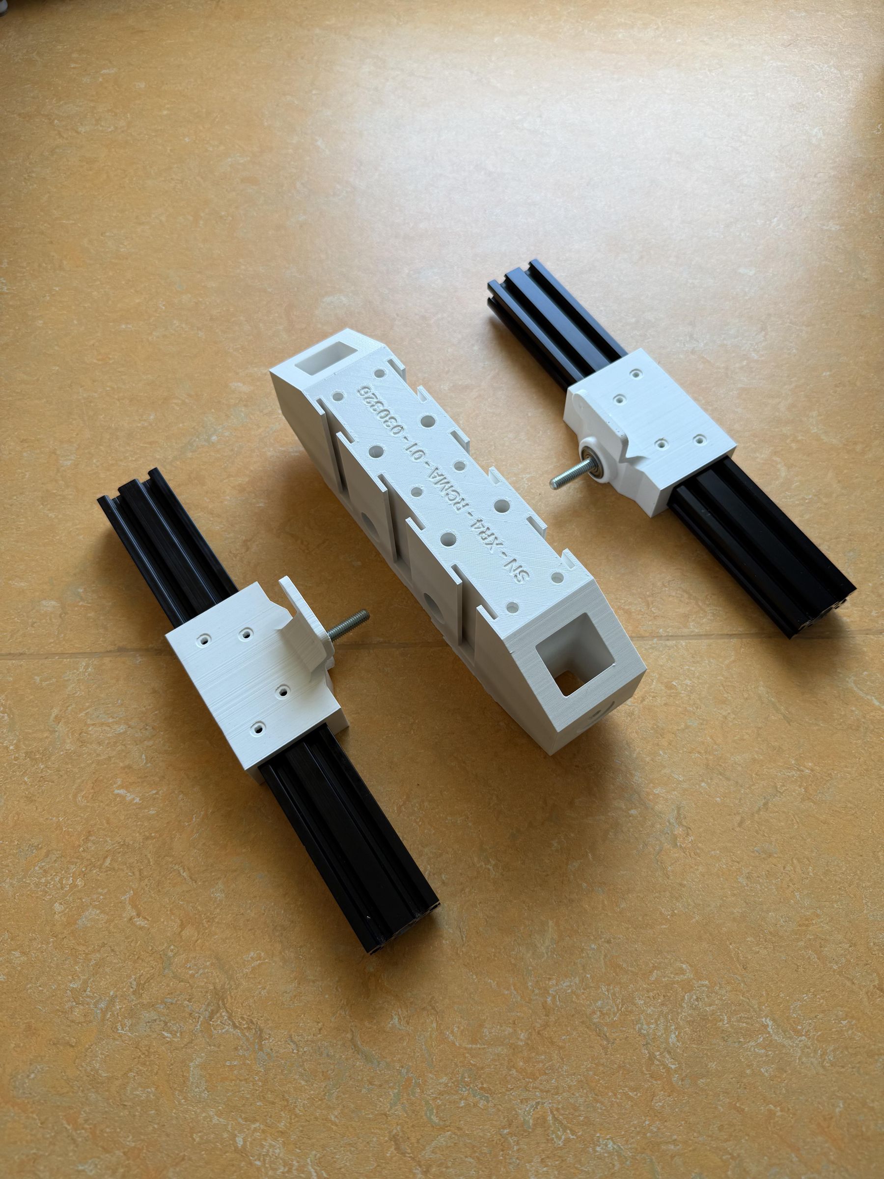
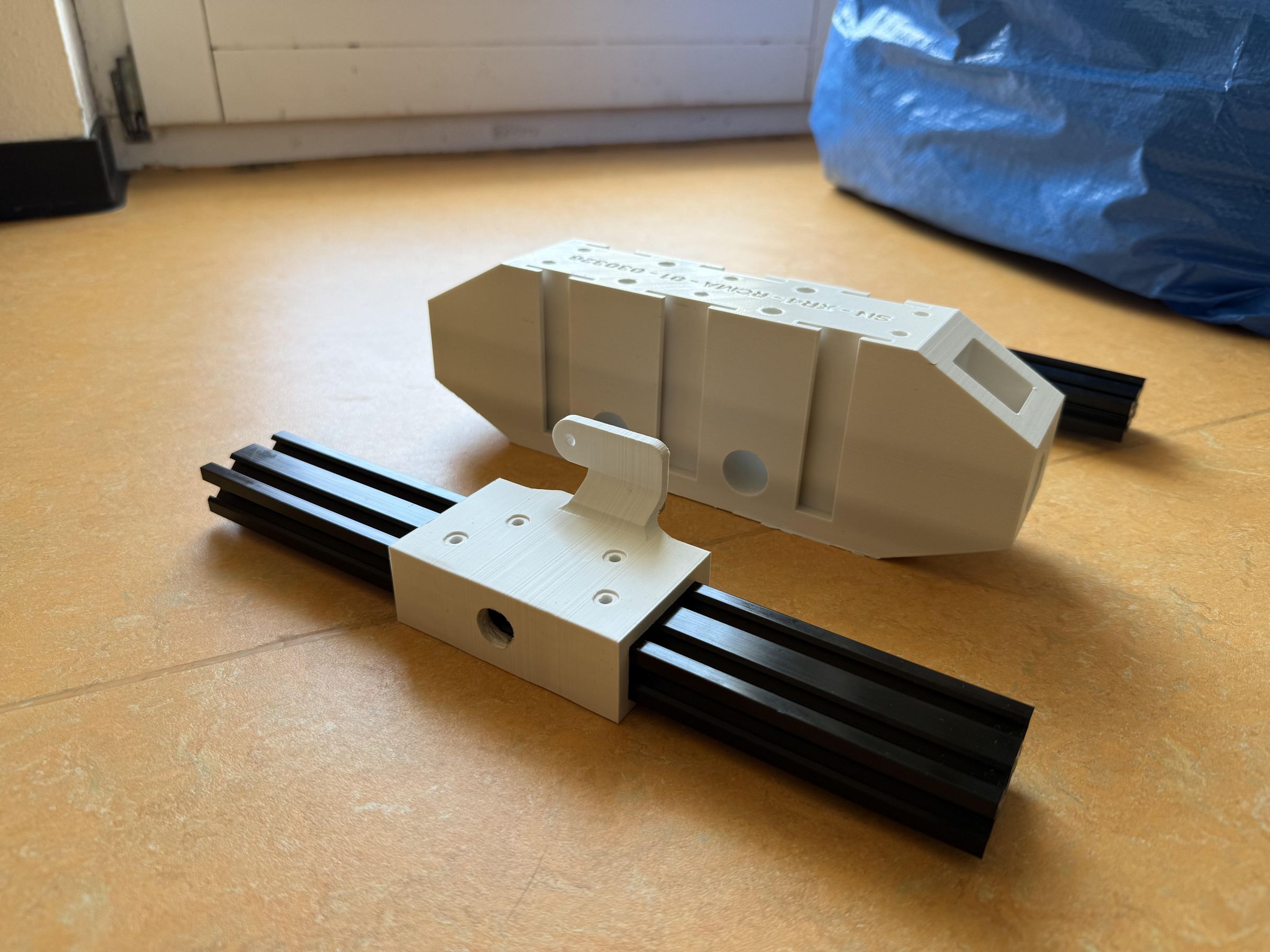
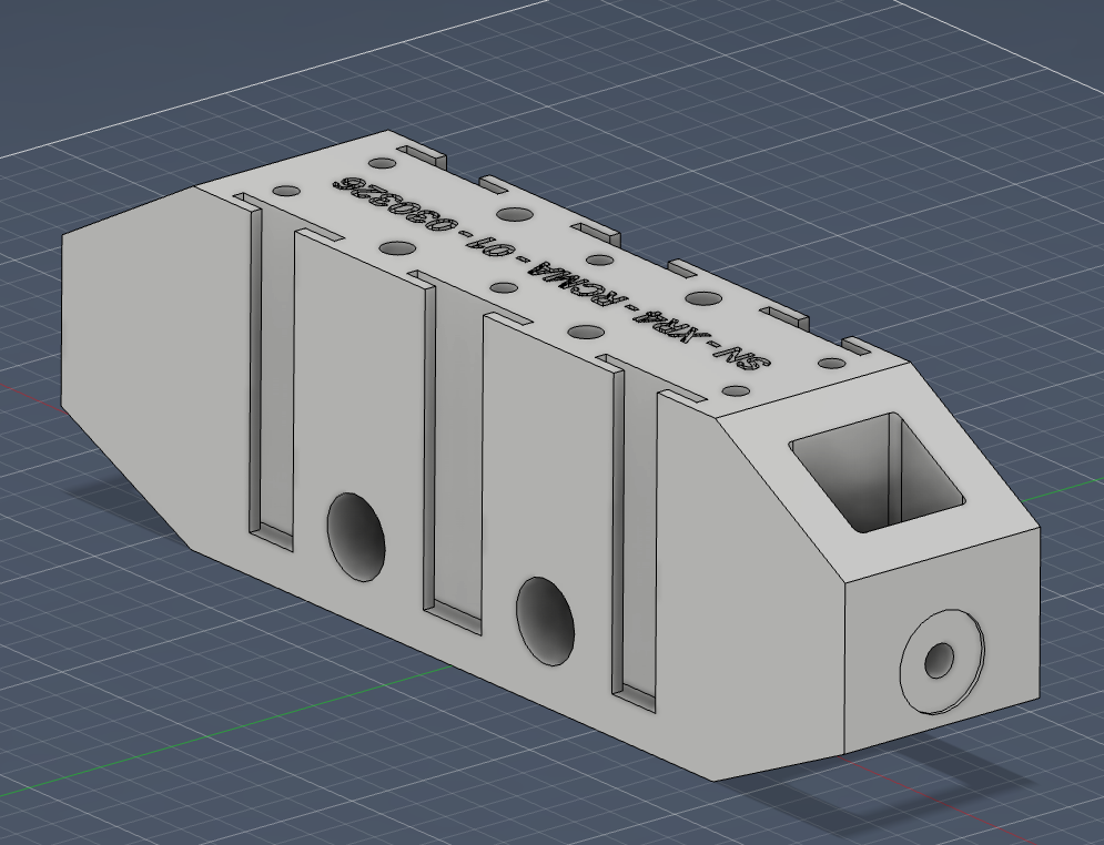
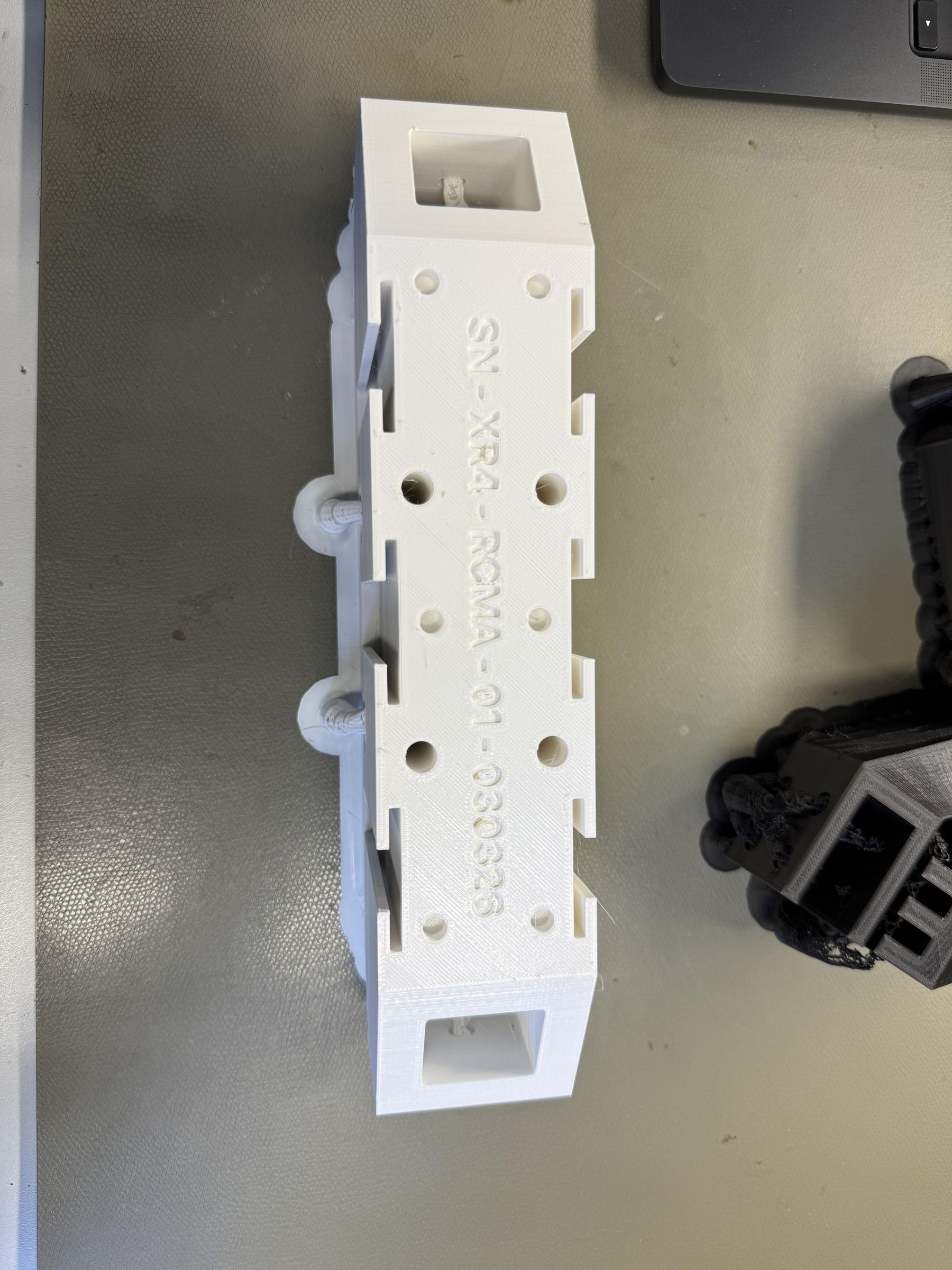
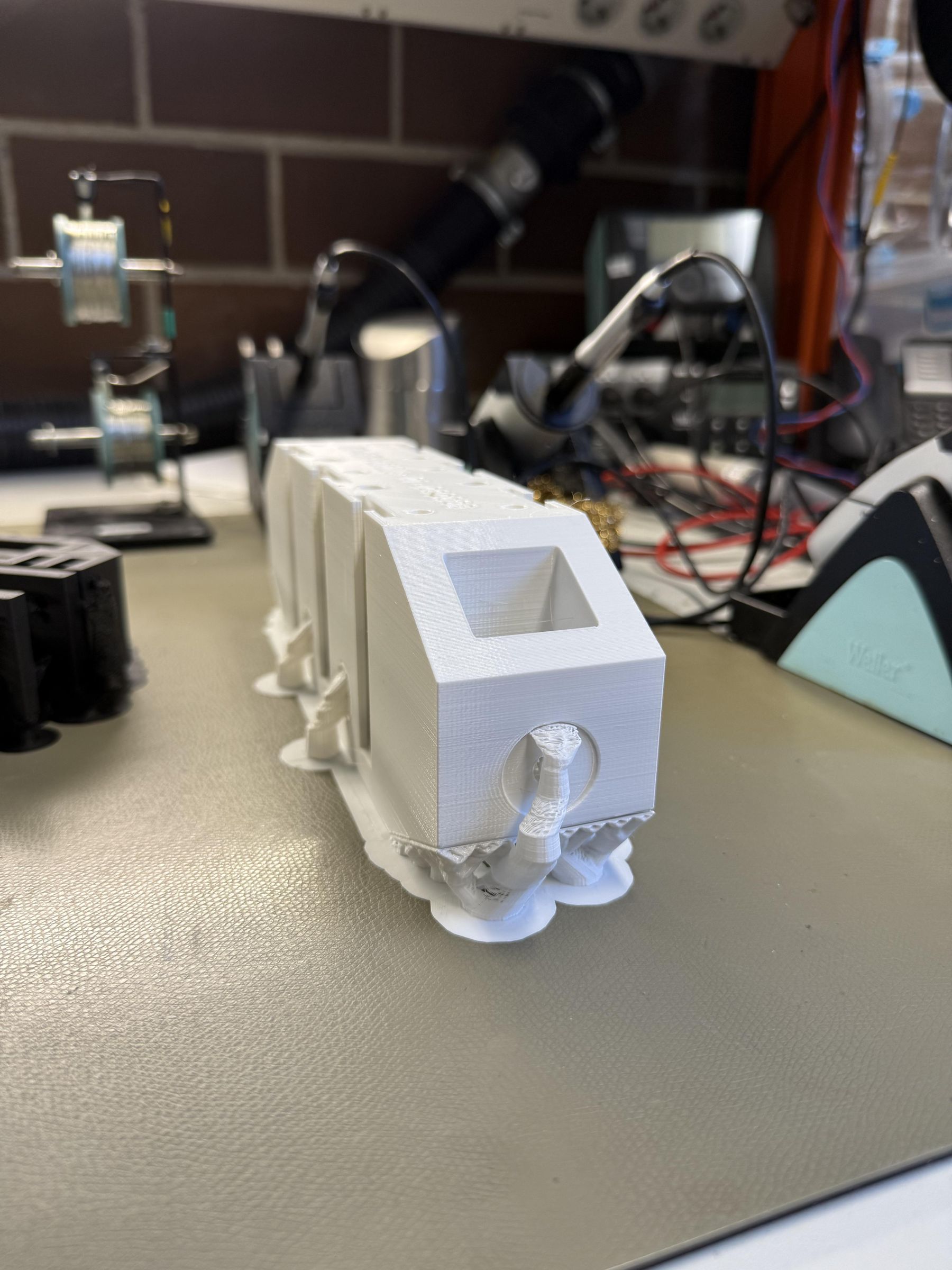
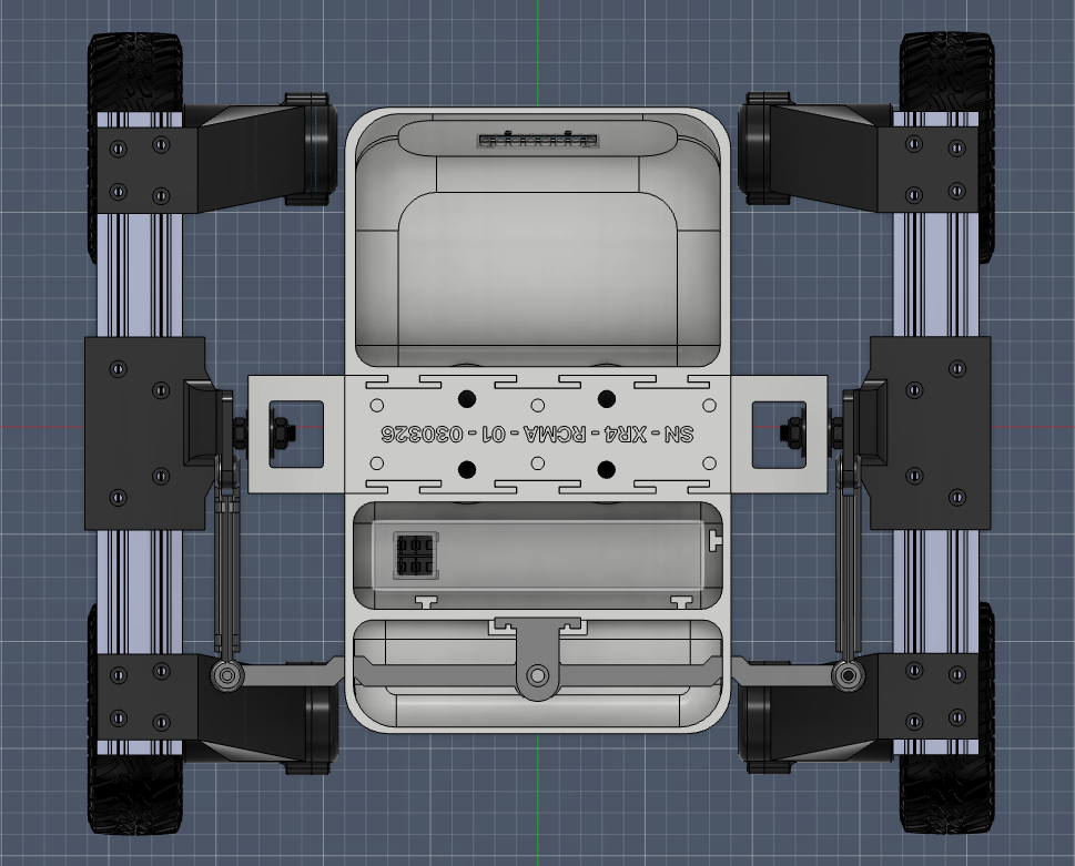
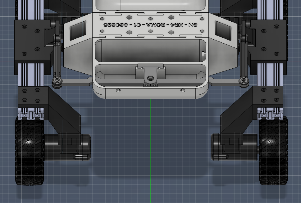
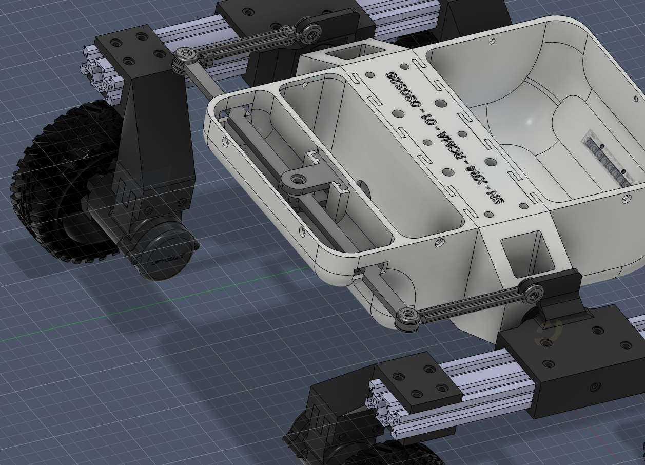
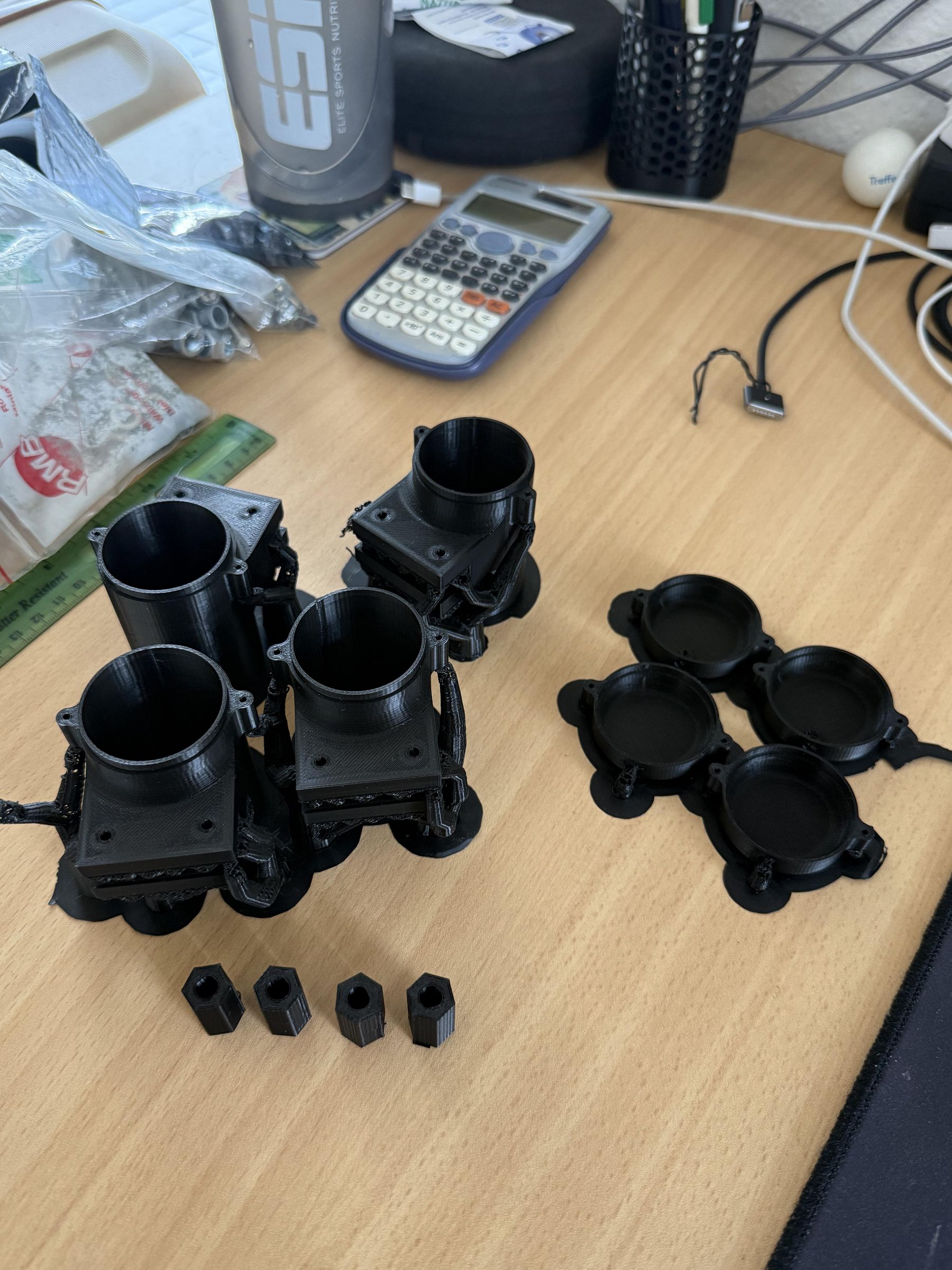
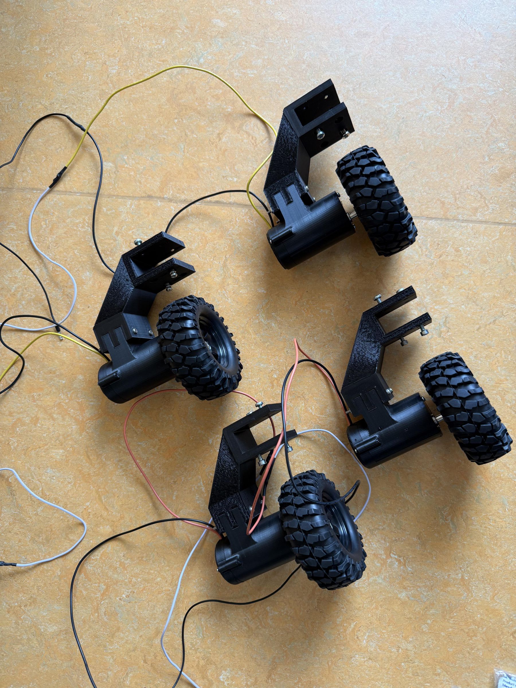
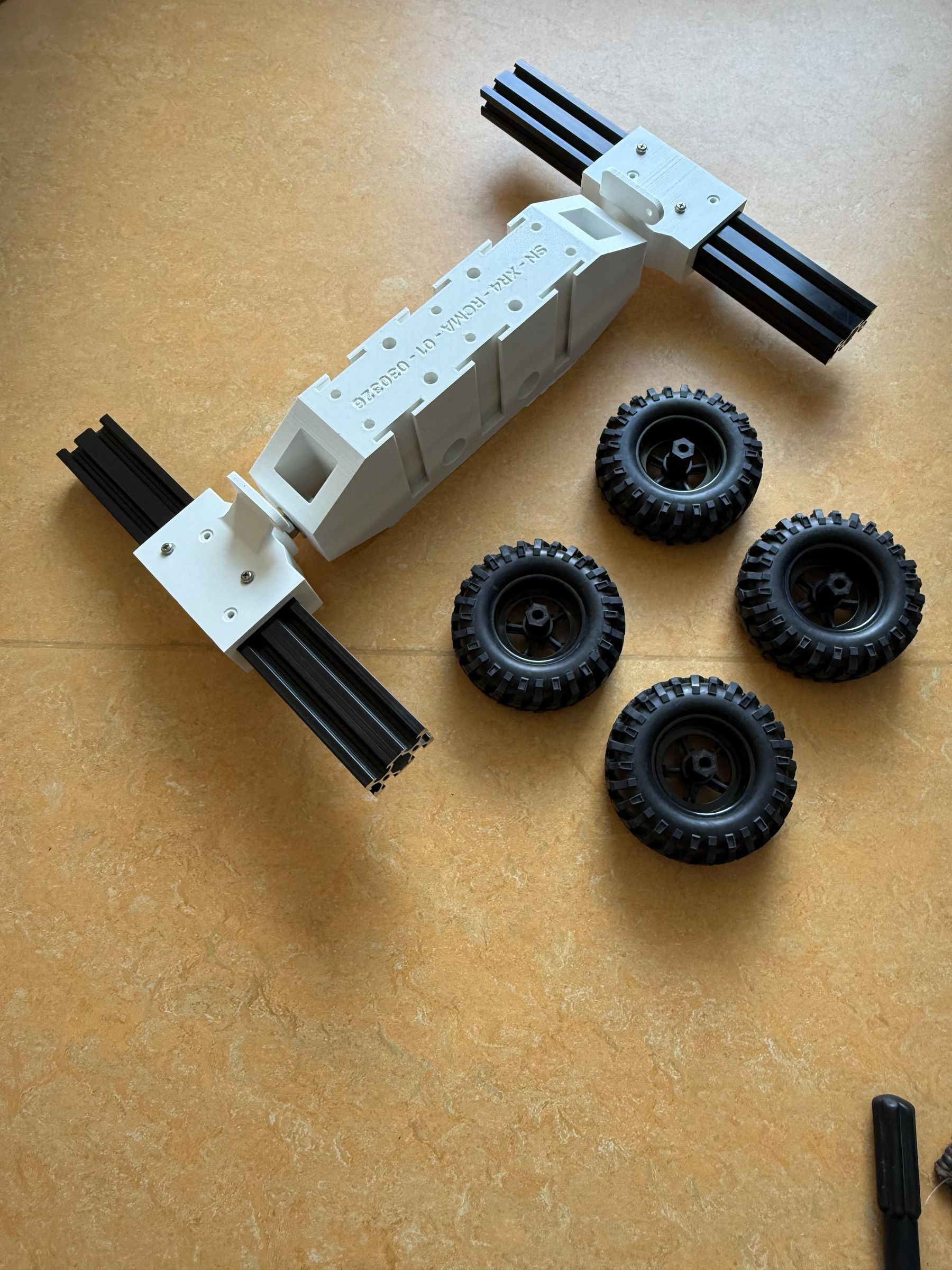
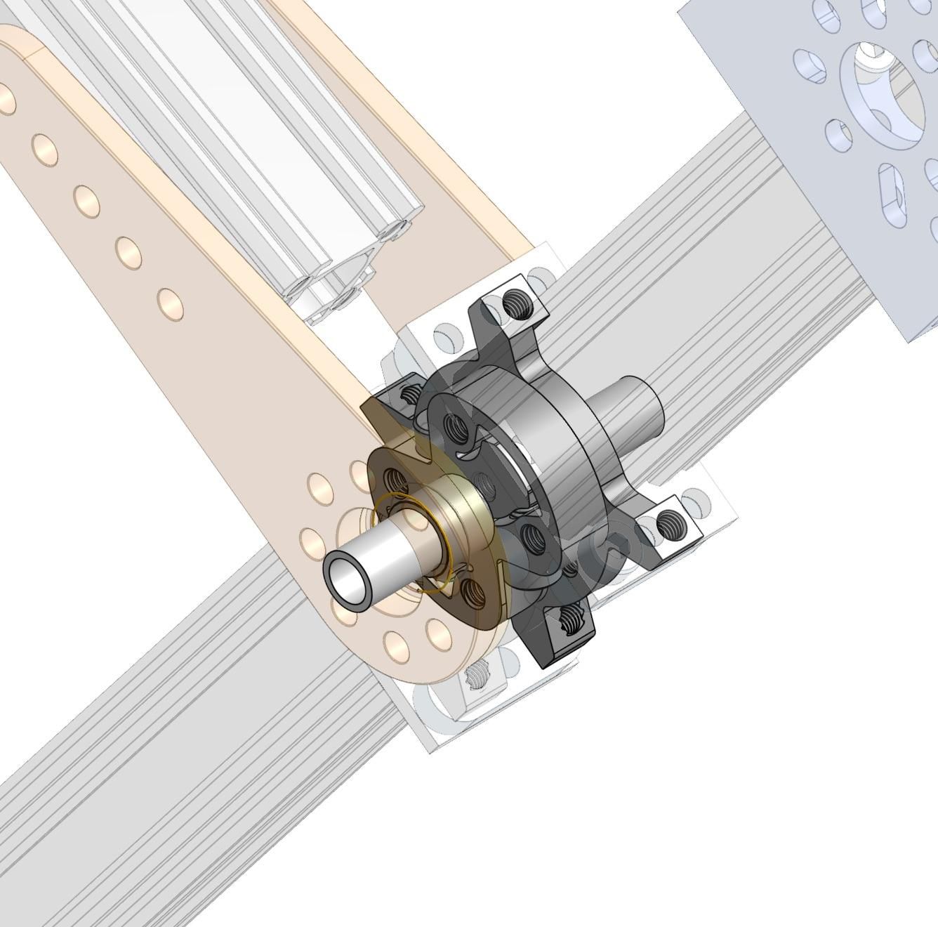
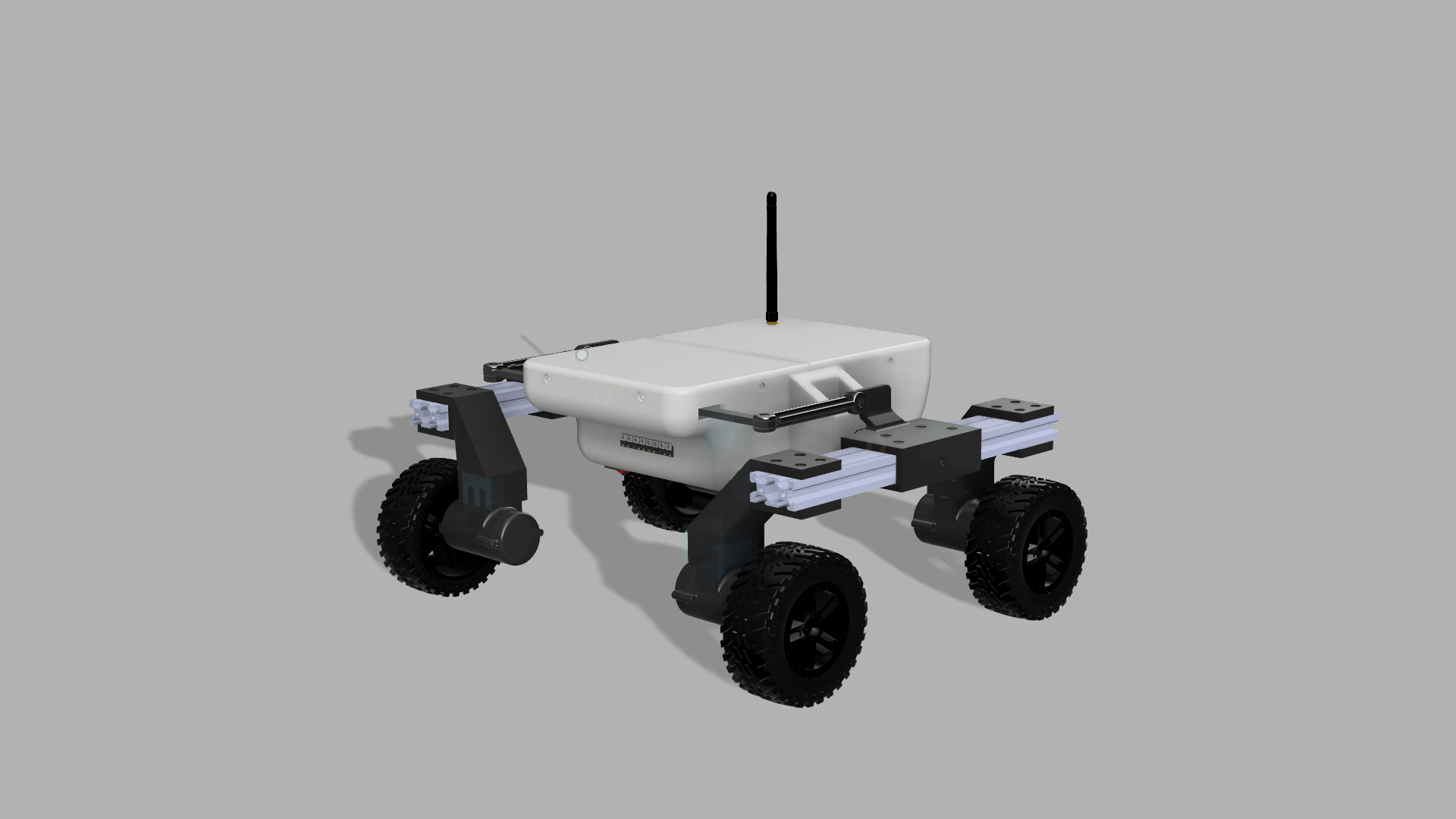
The suspension is of the Rocker Arm-type. It utilizes a pivoted arm with two driven wheels on each side. The two arms are linked together via a differential bar which is linked to the rover chassis via a hinged pivot. This concept is shown in Step 1.
Fastening Details:
- 2x M8 Bolts with 2 Nuts & 2 Washers each (CAD provided for reference, will link the Rocker arm to the center section)
- 22-44x M4 Screws with T-Slot Nuts (for securing Wheel struts and Rocker Pivot to Rocker arm) (see pictures)
- 8x M3 Screws with Nuts (length 43-35mm) (for securing Motor Casings to Wheel struts)
- 8x M2 Screws (for securing Motor Casing End Caps to Motor Casing)
- 12x M2 Screws (for securing the motors to the Motor Casing)
- 4x M4 Screws (for securing the tyres to the Motor Shaft Adapter)
Downloads
Rear Compartment / Electronics Bay
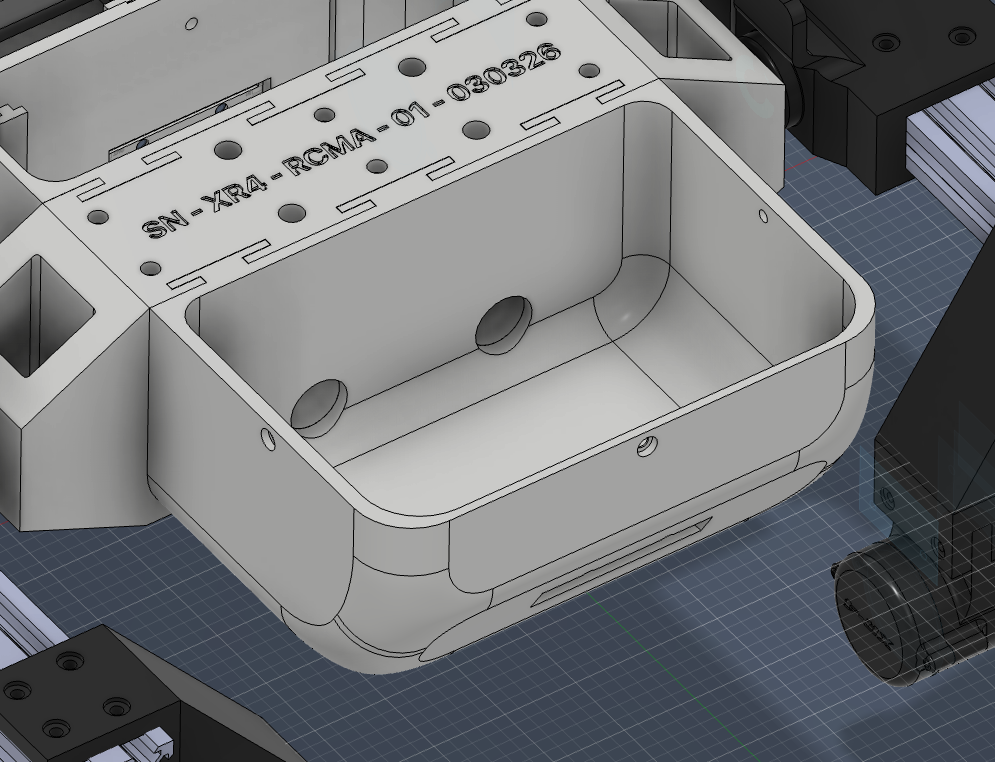
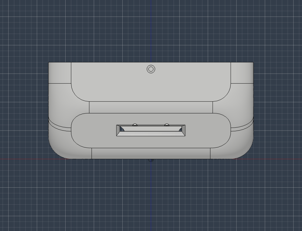
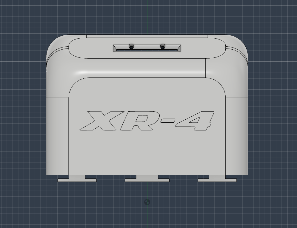
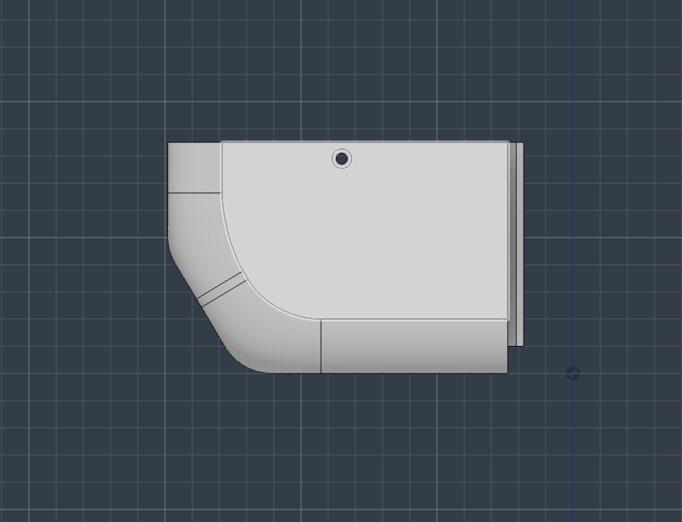
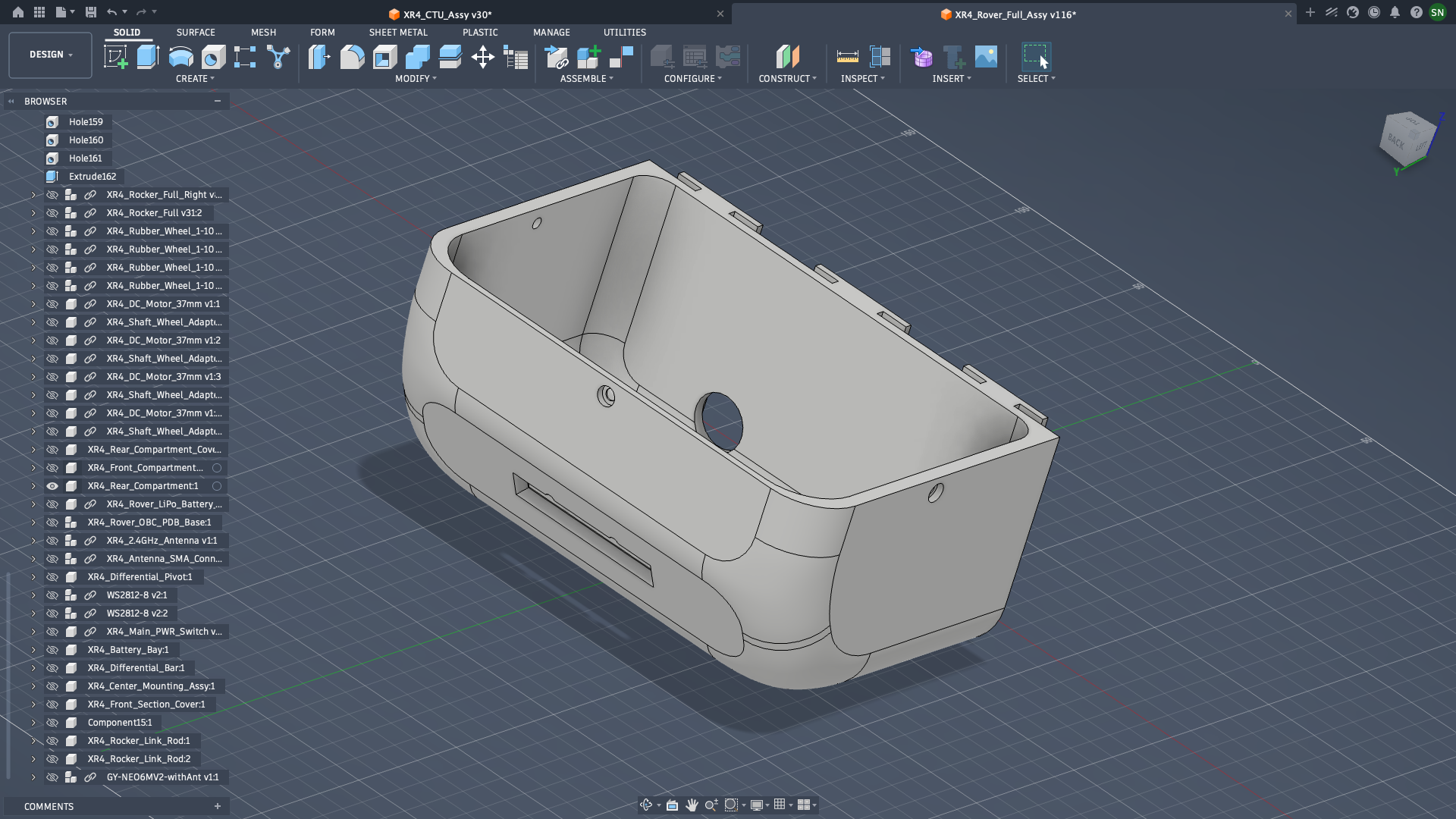
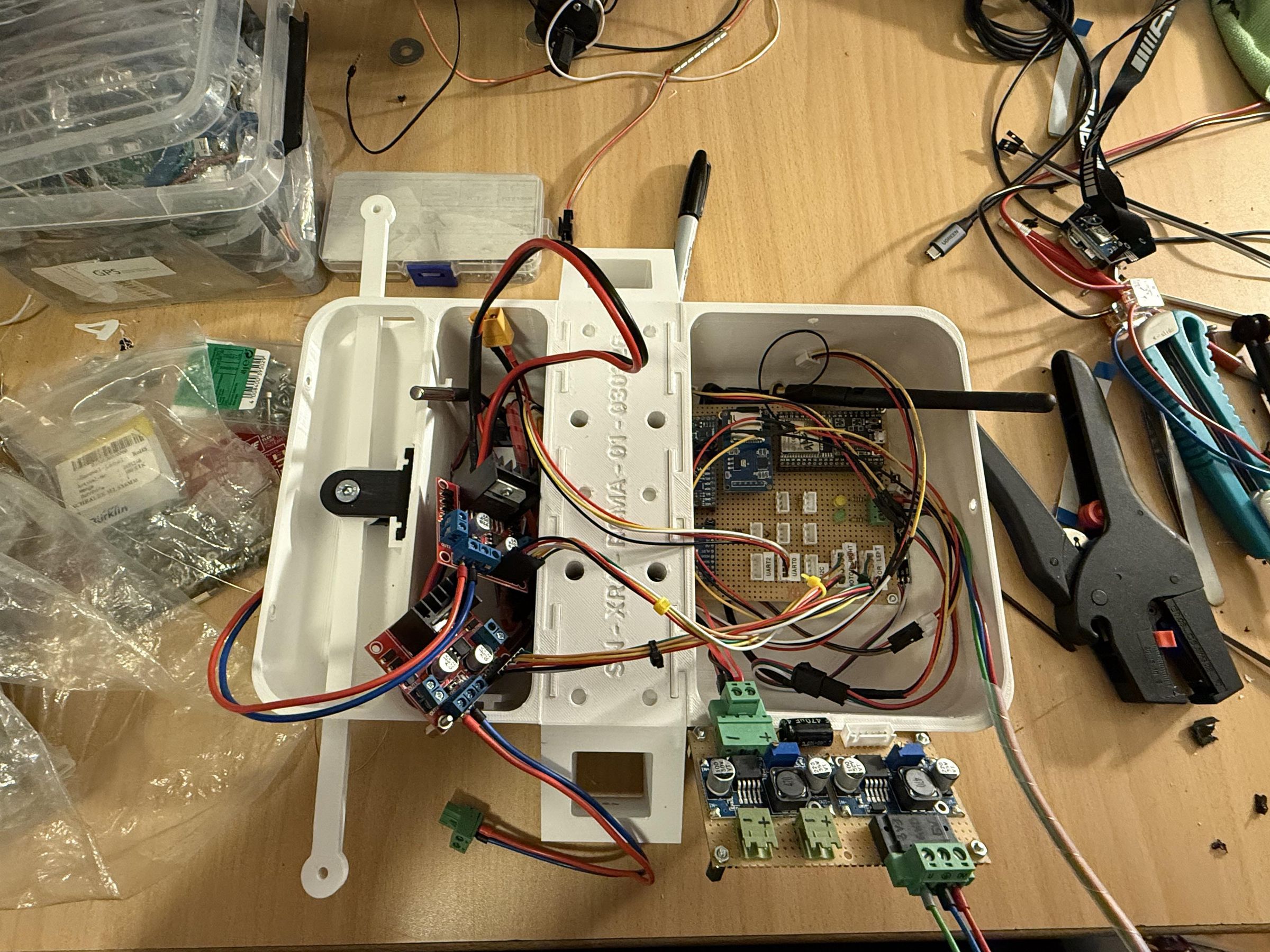
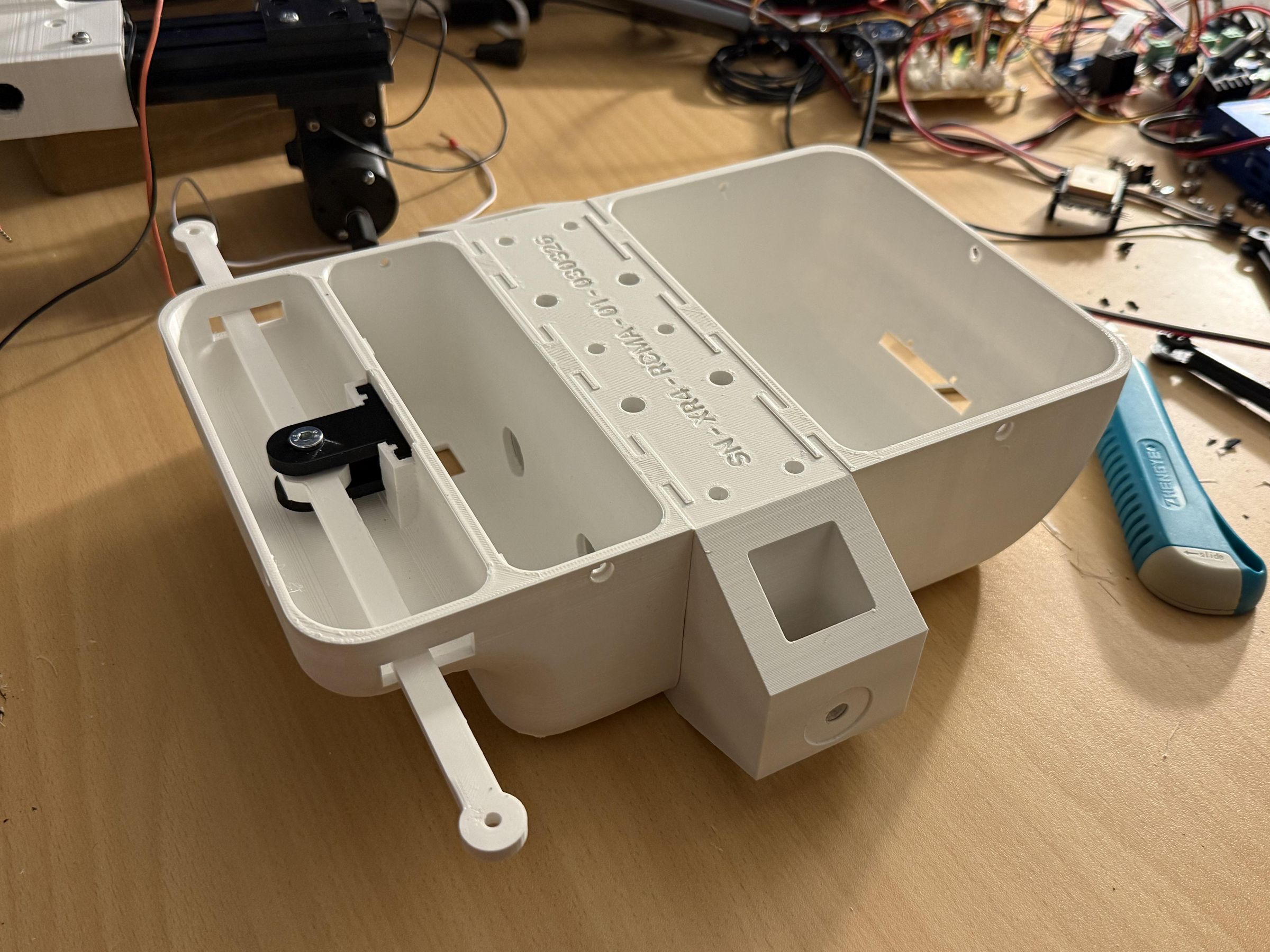
The rover structure is divided into two compartments / bays which slide into mounting grooves within the central section and held in place because of friction.
The rear compartment / electronics bay contains the Power Distribution Board, the Onboard Computer Board and the 2x L298N motor driver modules, along with the associated cabling. There is an 8-bit WS2812 RGB LED strip in the rear compartment, facing rearwards. This LED strip will display the status of the rover i.e. ARMED, WAITING FOR ARM, E-STOP, etc.
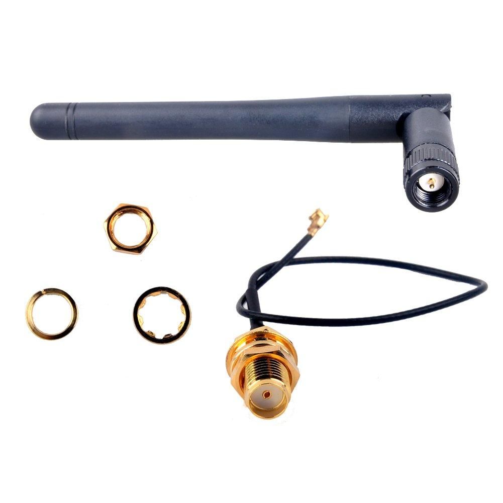
The cover for the rear compartment also has a mounting location for the 2.4GHz antenna which will be used by the ESP32 to communicate with the CTU over ESP-NOW. The Antenna is a standard 2.4GHz one, with a female SMA to u.FL pigtail connector and cable for panel mount. The cable is connected via the u.FL connector to the ESP32 antenna connector. The pictures of the antenna are available in the Components section.
It was a slight challenge to fit all cabling and the boards into the rear compartment, but it was successfully done by shortening some cables which didn't need to be very long.
The compartment can be joined together with the Center section using the slide-in guide rails and does not require any screws.
Fastening Details:
- 4x M4 Screws with Nuts and Washers (for Rocker link rods)
- 1x M6 Screw with Nuts (for Rocker differential bar)
- 4x M3 Screws with Nuts (for Rear section cover)
- 2x M2 Screws with Nuts (for Taillight WS2812 RGB LED Strip)
Front Compartment / Battery Bay
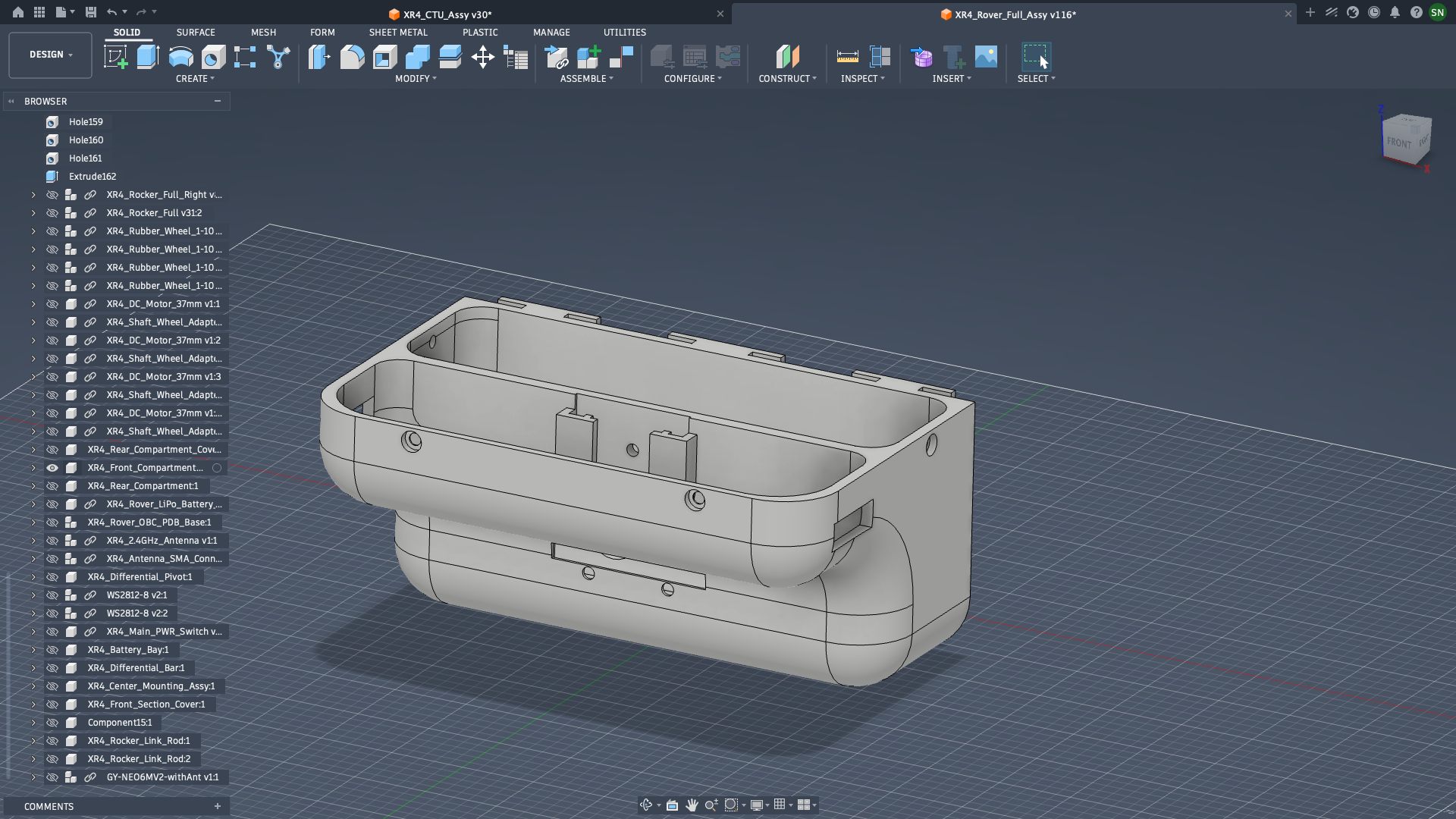
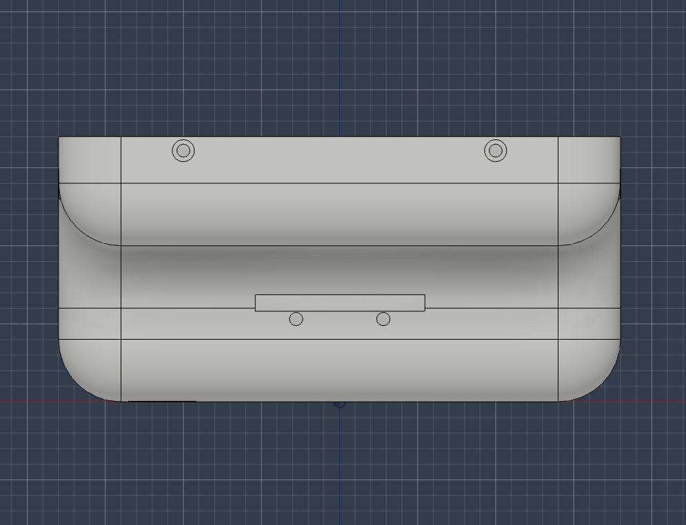
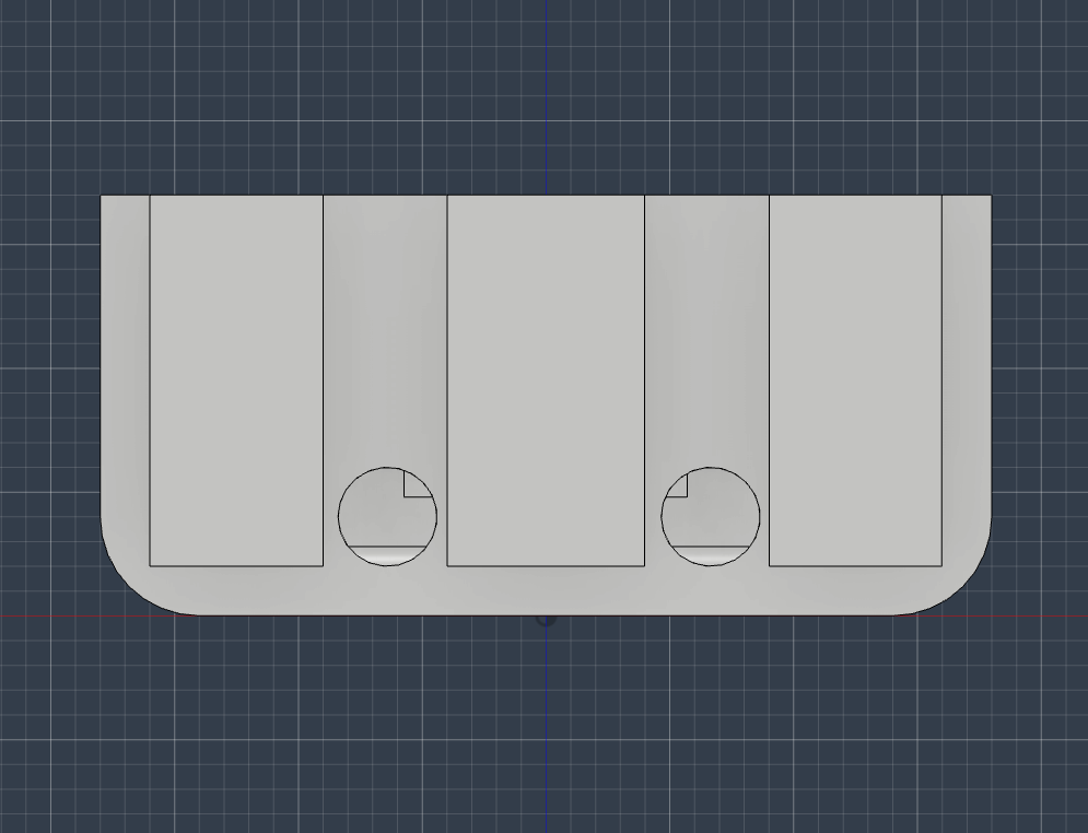
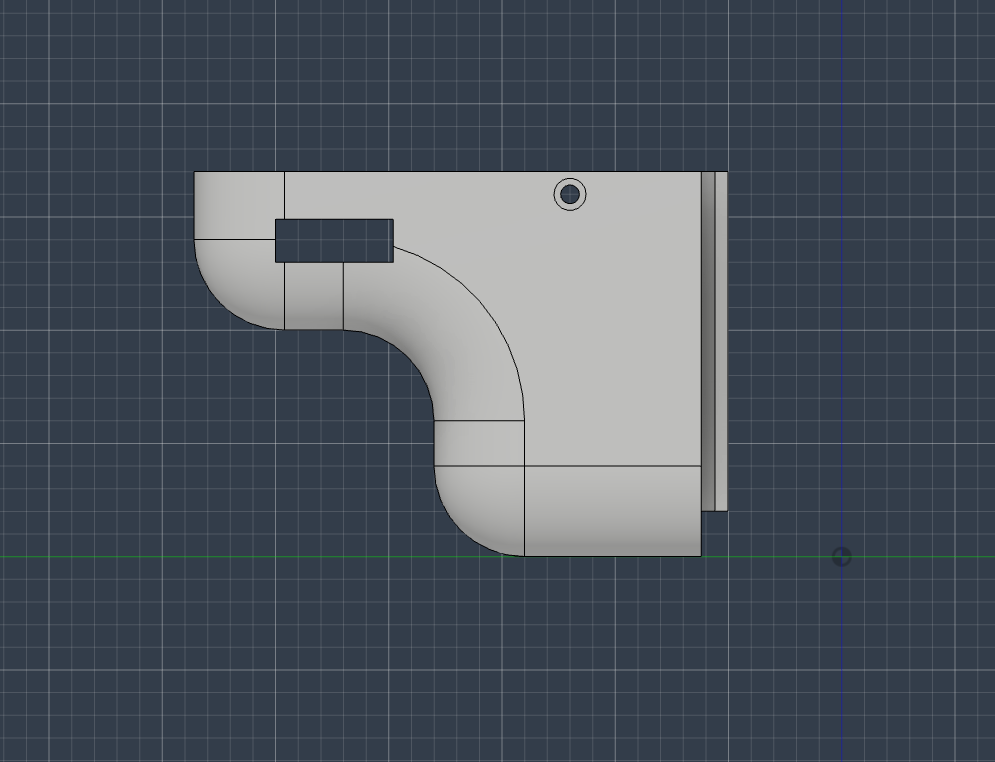
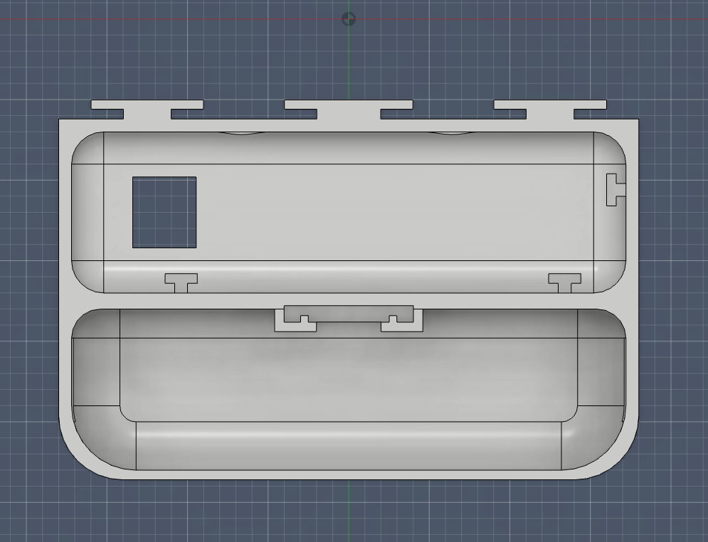
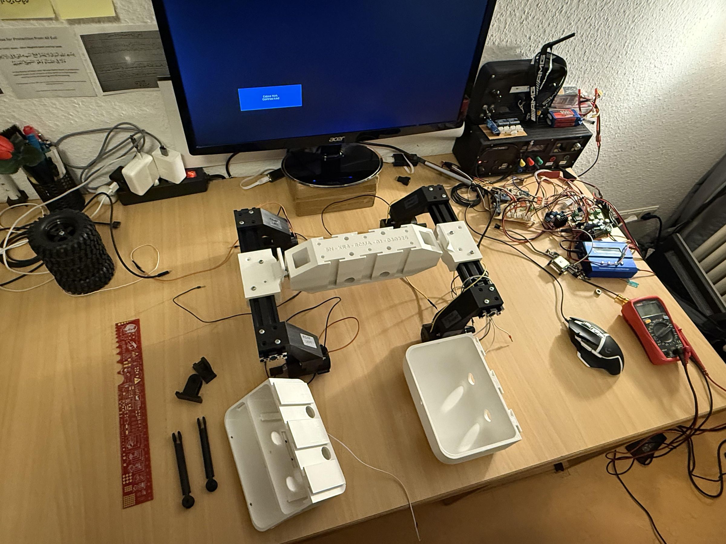
The front compartment follows from the rear one in its concept and mounting technique. It has a distinct shape, which was inspired by the LeoRover and which was intended to give the rover a distinctive "face". It is essentially the battery bay and also contains the rover's headlights and it an important structural component since it serves as the point which links the rover's two rocker arms to each other.
It contains a mounting cutout for an 8-bit RGB LED strip, which would be used as the headlights, as well as cutouts for the MARQUART power switch, cabling and for the differential beam which will connect to a pivot and link the two rockers together.
The compartment can be joined together with the Center section using the slide-in guide rails and does not require any screws.
Fastening Details:
- 4x M4 Screws with Nuts and Washers (for Rocker link rods)
- 1x M6 Screw with Nuts (for Rocker differential bar)
- 4x M3 Screws with Nuts (for Front section cover)
- 2x M2 Screws with Nuts (for Headlight WS2812 RGB LED Strip)
Powertrain & Steering
.png)
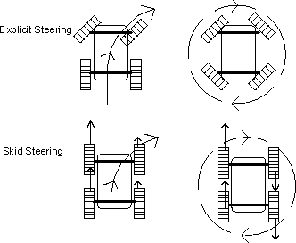
The XR-4 uses a compact four-wheel-drive powertrain designed for reliable operation in outdoor and off-road environments. Each wheel is driven by its own 12V DC 100RPM motor through a planetary gearbox, providing high torque at low speeds and enabling precise control through PWM. The MCPWM (Motor Control PWM) unit of the ESP-IDF framework is used on the microcontroller, which drives the motors through two L298N full H-bridge motor drivers. The motors are assigned by sides i.e. each L298N controls motors on each side. This distributed drive architecture eliminates the need for mechanical differentials while allowing the rover to traverse uneven terrain with excellent traction and stability.
Steering is achieved through skid steering (also known as differential steering), where the rover changes direction by varying the rotational speed of the wheels on the left and right sides. By driving one side faster than the other—or even reversing one side while the other moves forward—the platform can execute smooth turns as well as zero-radius, in-place rotations. This approach simplifies the mechanical design while providing exceptional maneuverability in confined spaces.
The combination of independently driven wheels and skid steering makes the rover well suited for autonomous navigation, research, and inspection tasks. The system offers robust mobility across a wide range of surfaces while maintaining a compact, durable, and low-maintenance drivetrain.
Power & Electronics
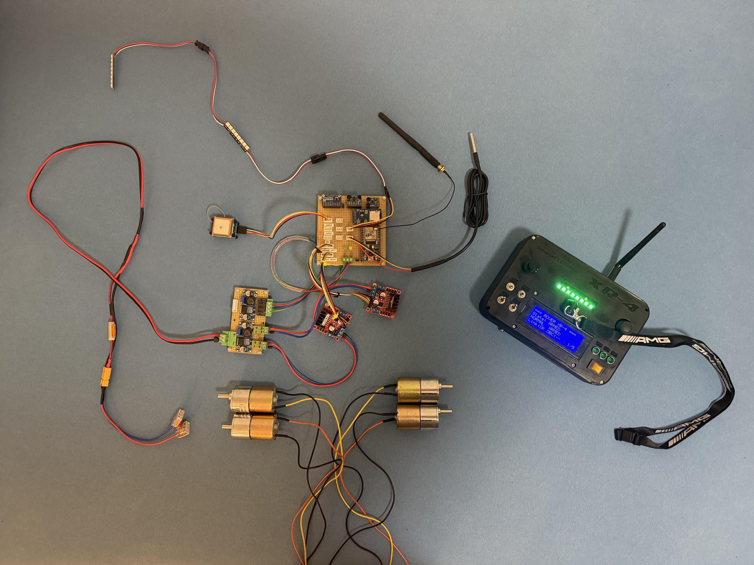
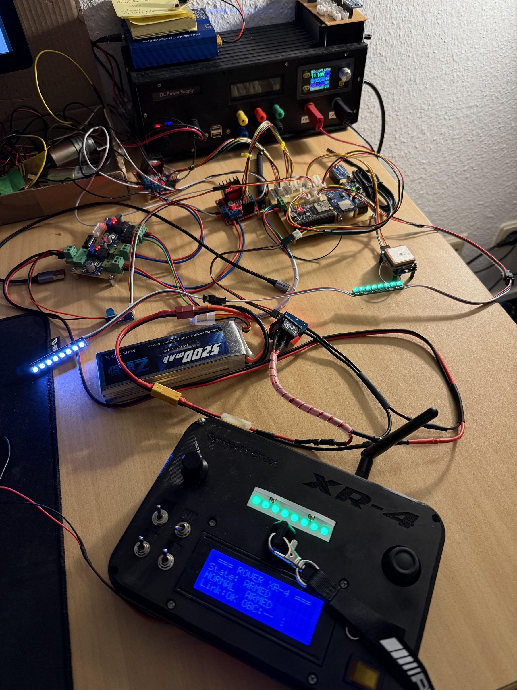
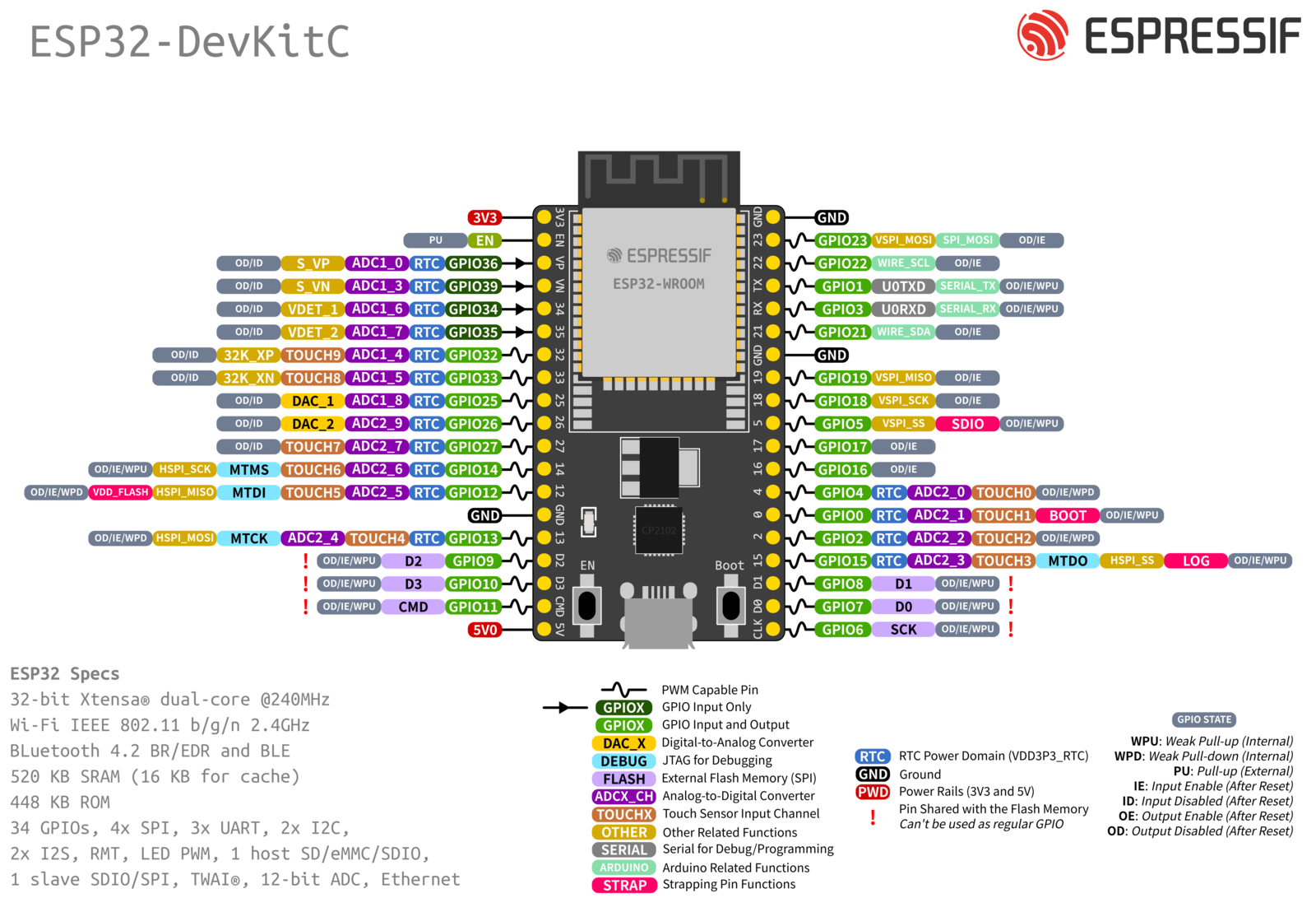
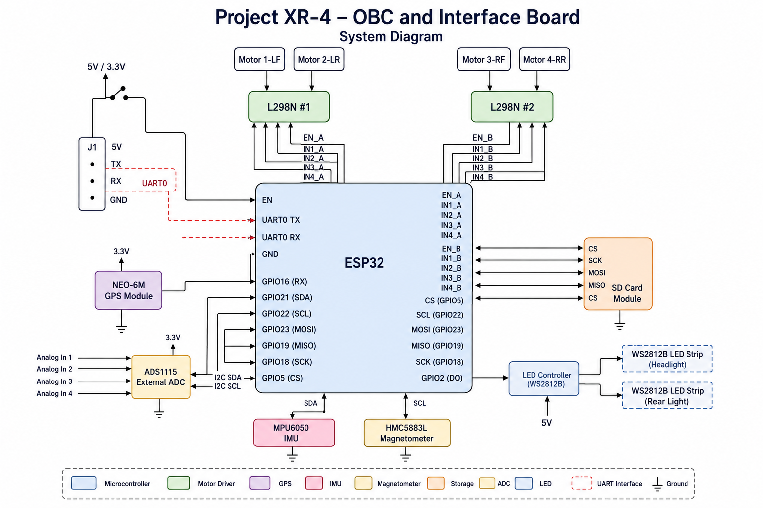
The Power and Electronics subsystems are the literal heart of the rover.
Power Subsystem
This system primarily consists of the battery, main bus fuse (5A automotive blade fuse in receptacle) and the power distribution board. The main bus voltage is fed directly to the 2x L298N motor drivers, each of which drives two motors, divided by the right and left side motors.
The power distribution board uses two DC/DC step down switching converters to generate +5V and +3.3V voltages.
I use an ACS712 current sensor on the main bus to measure the current and a generic potential divider module to monitor the voltage. This will be replaced in the near future by an INA228 power monitoring module which will consolidate precise voltage and current monitoring in a single module. I will be using the generic potential divider modules and INA219 current sensors on for voltage and current monitoring on the +5V and +3.3V buses.
The wire gauge for the main bus is 18AWG and for the motor cables, motor driver power and the +5V and +3.3V buses are 21AWG. Sensor signals use 28AWG wires with JST-XH female plugs and male connectors on the boards.
Onboard Computer and Sensors
The Electronics subsystem consists of the OBC and associated sensors. These are the general characteristics:
Microcontroller: ESP32-WROOM-32U Dev Module
IMU: MPU6050 6-axis IMU (I2C)
Compass: QMC5883L (I2C)
Temperature Sensor: DS18B20 OneWire (Digital)
Headlights and Rear Status Light: WS2812E 8-Bit RGB LED Strips (Digital)
Voltage Sensor: Generic Voltage Divider Module (Analog)
Current Sensor: ACS712 (Analog) & INA219 (I2C)
GPS: uBlox NEO-6M GPS Module (UART)
The OBC functions as a relatively low-level control and interfacing computer which handles control and communication functions. It can be integrated via UART with a high-level, single-board computer such as a Raspberry Pi or an Intel x86-based Mini PC which will serve as a Mission Computer running something like ROS/ROS2 and using a 2D LIDAR, a camera (could be an RGBD camera) and perhaps a better IMU. The Mission Computer will allow autonomous navigation and driving and unlock the full potential of this rover platform since it is intended to be a platform for autonomous mobile robotics-related development on a budget.
The following documentation document serves as the main Interface Control Document and contains the pin-mapping for the OBC and CTU, detailing all sensors and components connected to the ESP32s.
Downloads
Software
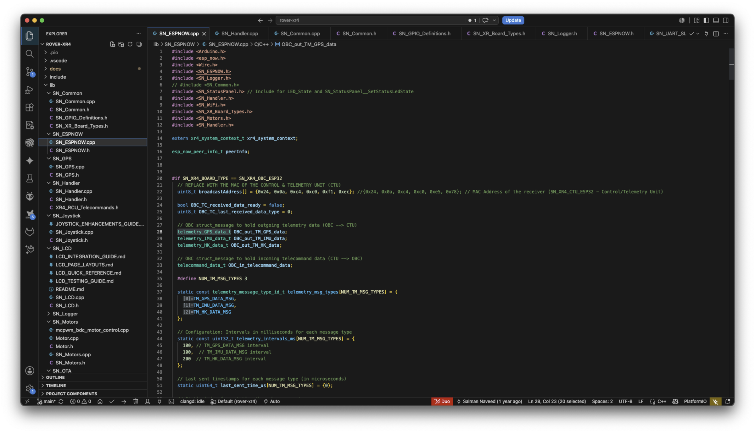
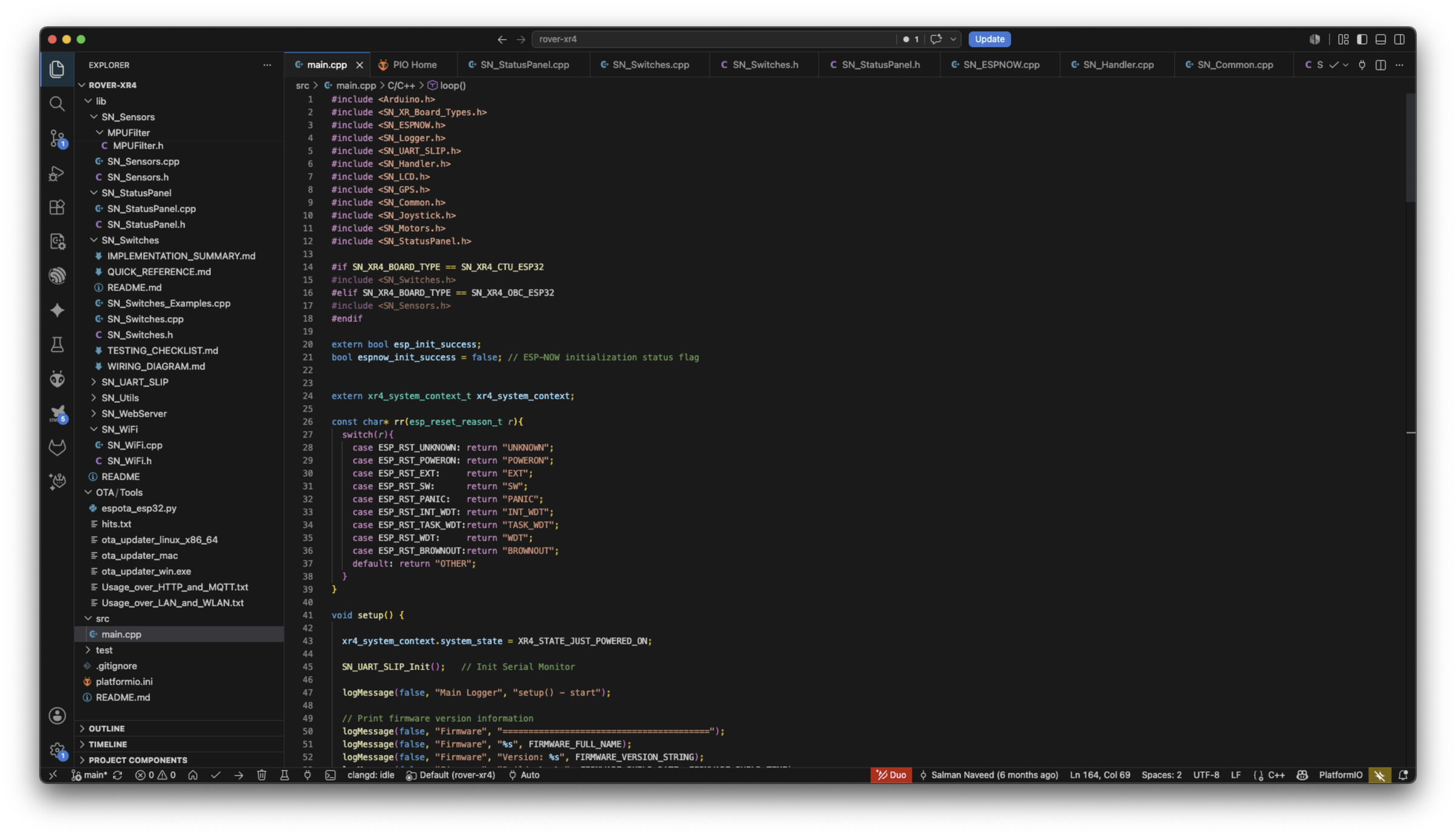
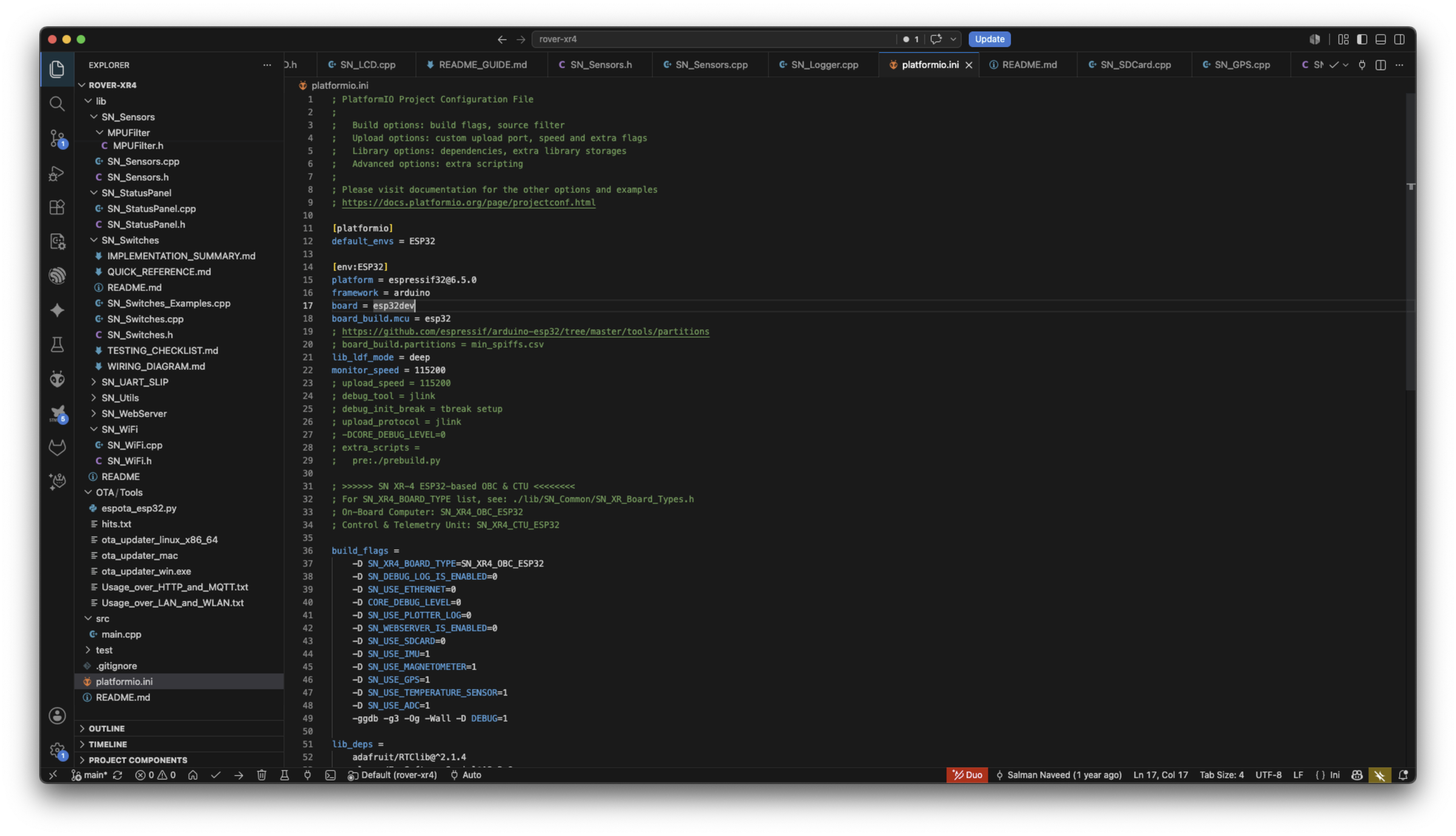
I used a single codebase for the software running on the OBC and the CTU. Both run separate versions of a common firmware and the target device can be chosen using environment variables defined in the platformio.ini file.
The development was done within PlatformIO in VSCode and the entire codebase is available in the monorepo at the following GitHub link. The README also provides a lot of background and instructions on getting started. I will also be improving the README to make it easy to understand.
GitHub
Getting Started
I would recommend that you use the PlatformIO extension within VSCode to work with the code.
Open a New Terminal in VSCode and clone the repository.
You can then use the build options within the PlatformIO toolbar on the left to build the firmware for either the CTU or OBC and then upload it to the ESP32 boards.
Control Unit: Design and Assembly
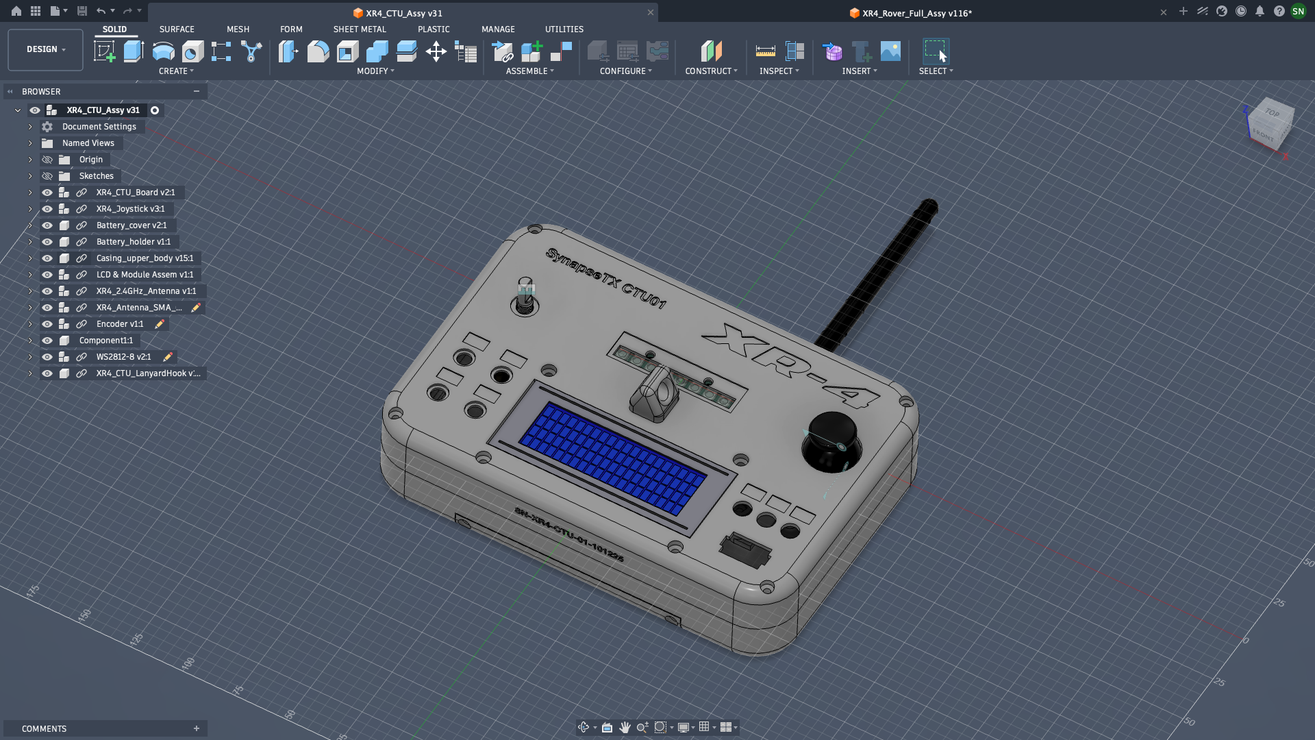
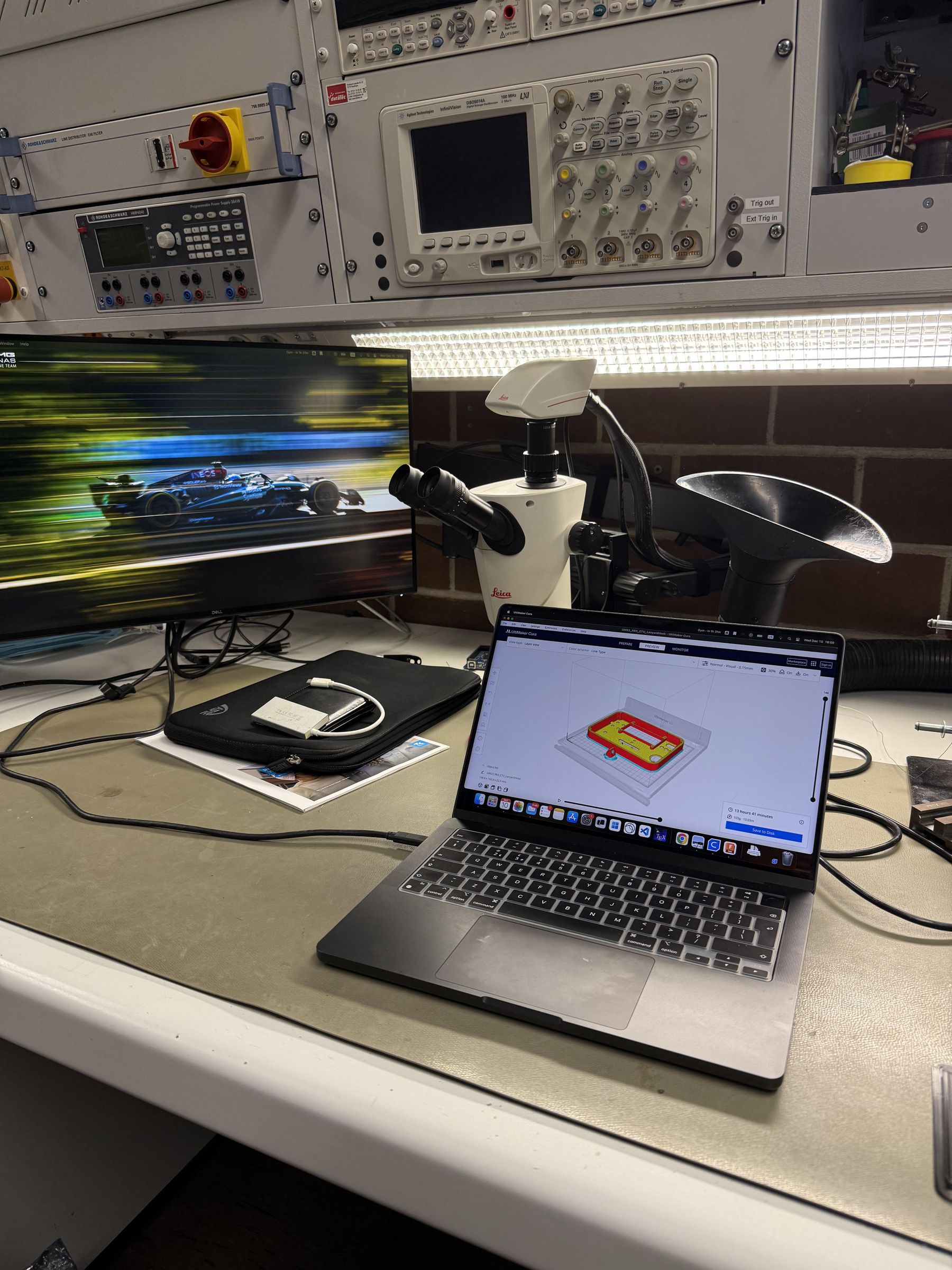
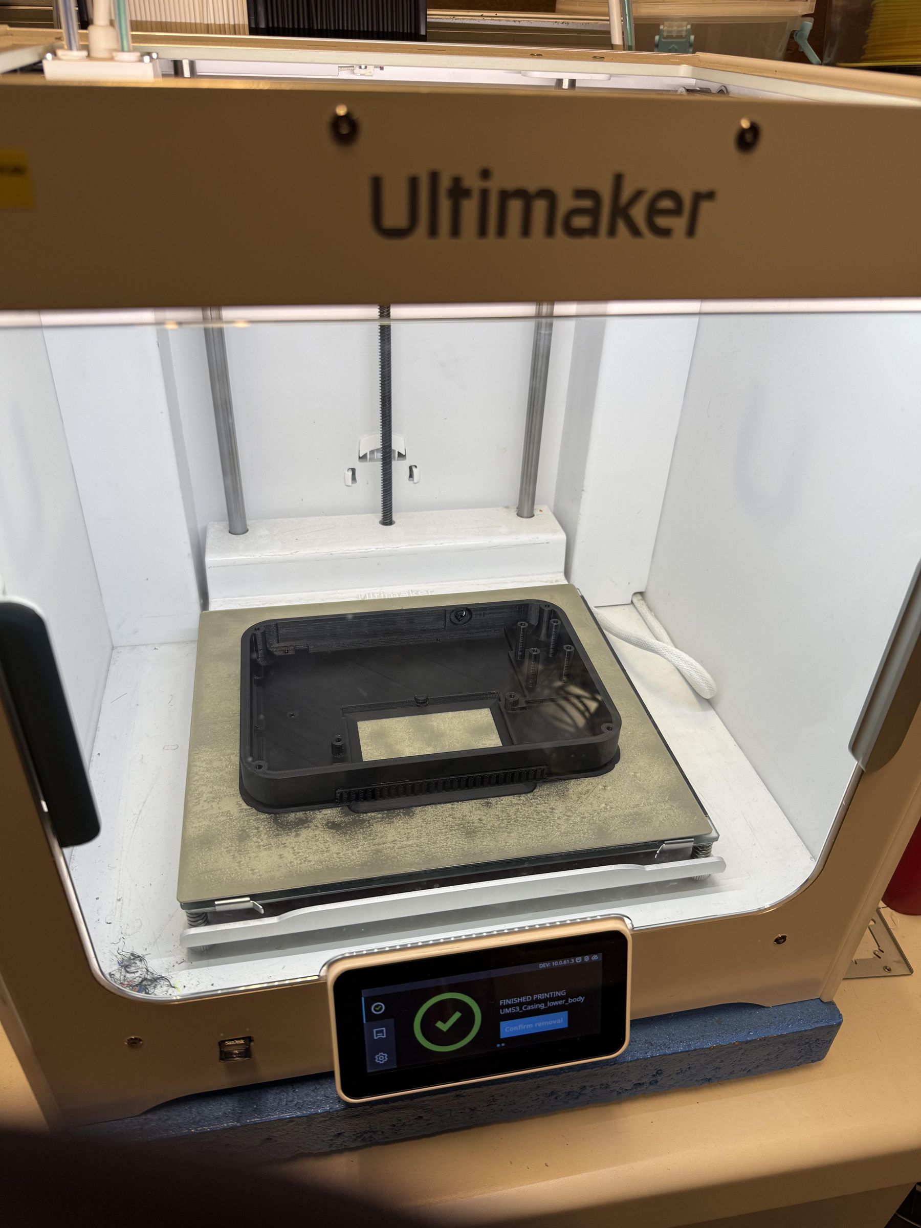
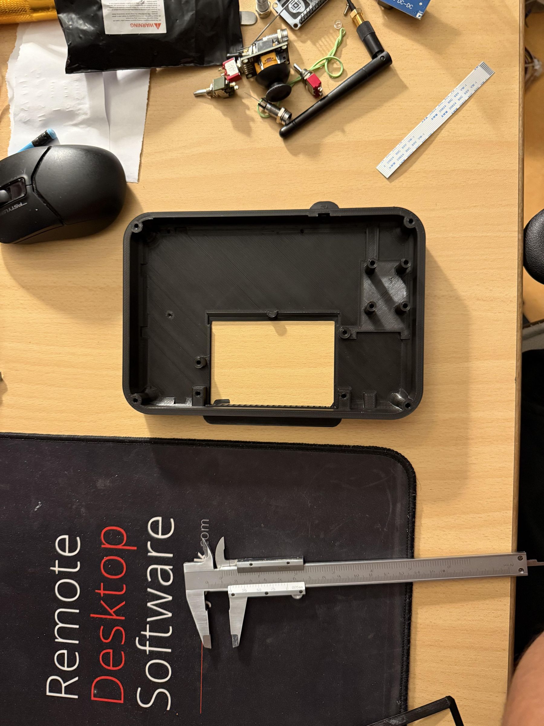
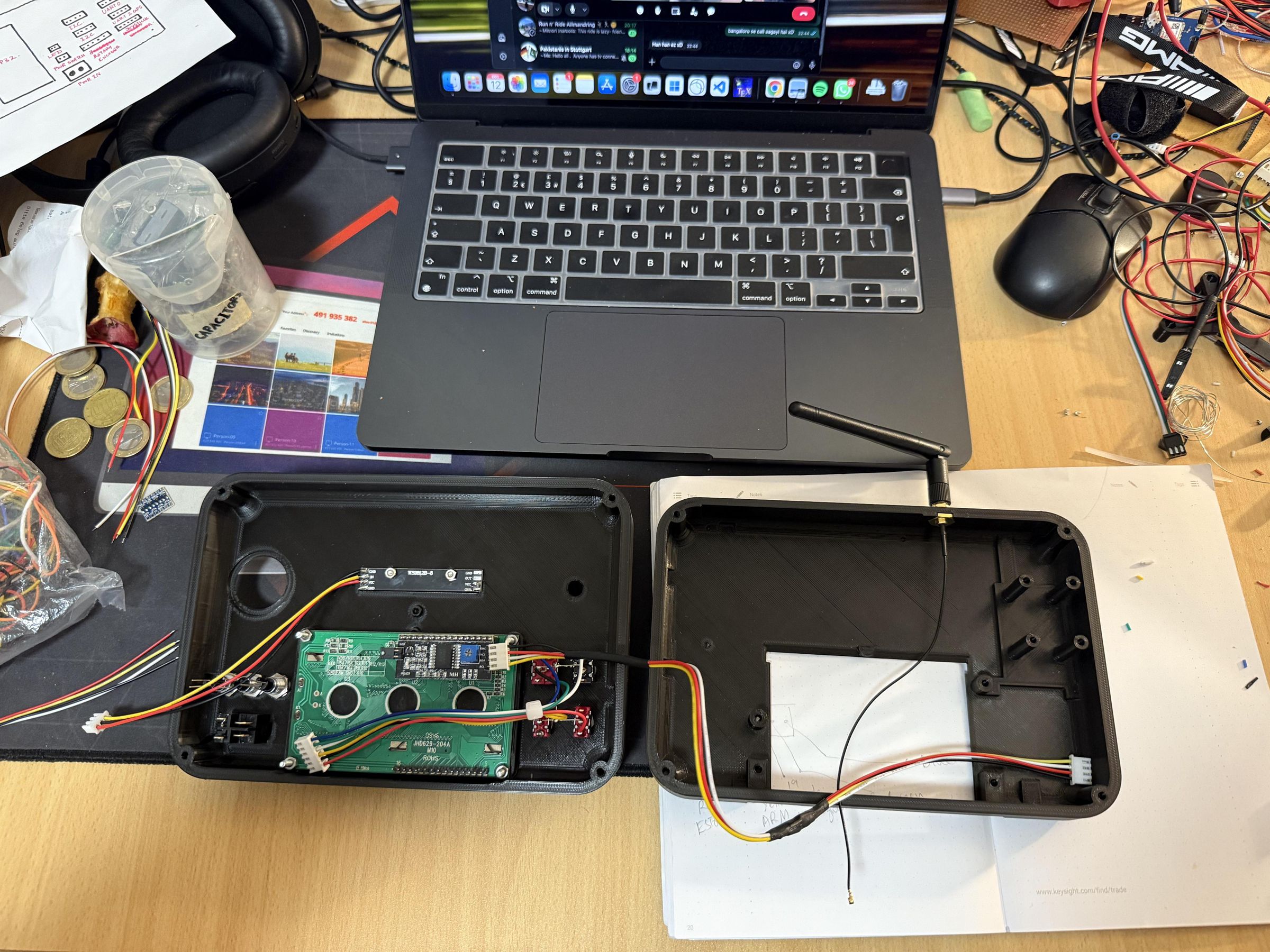
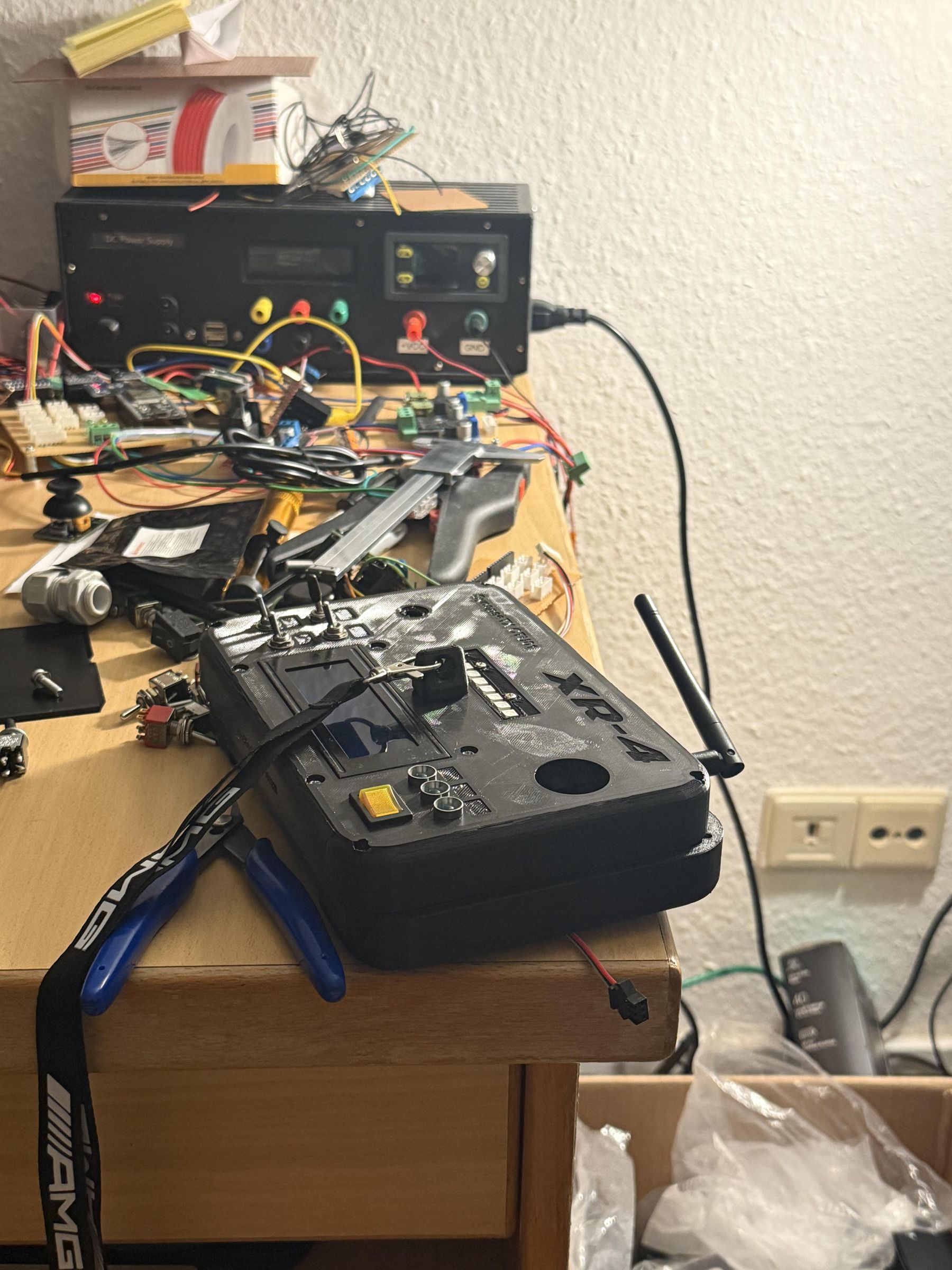
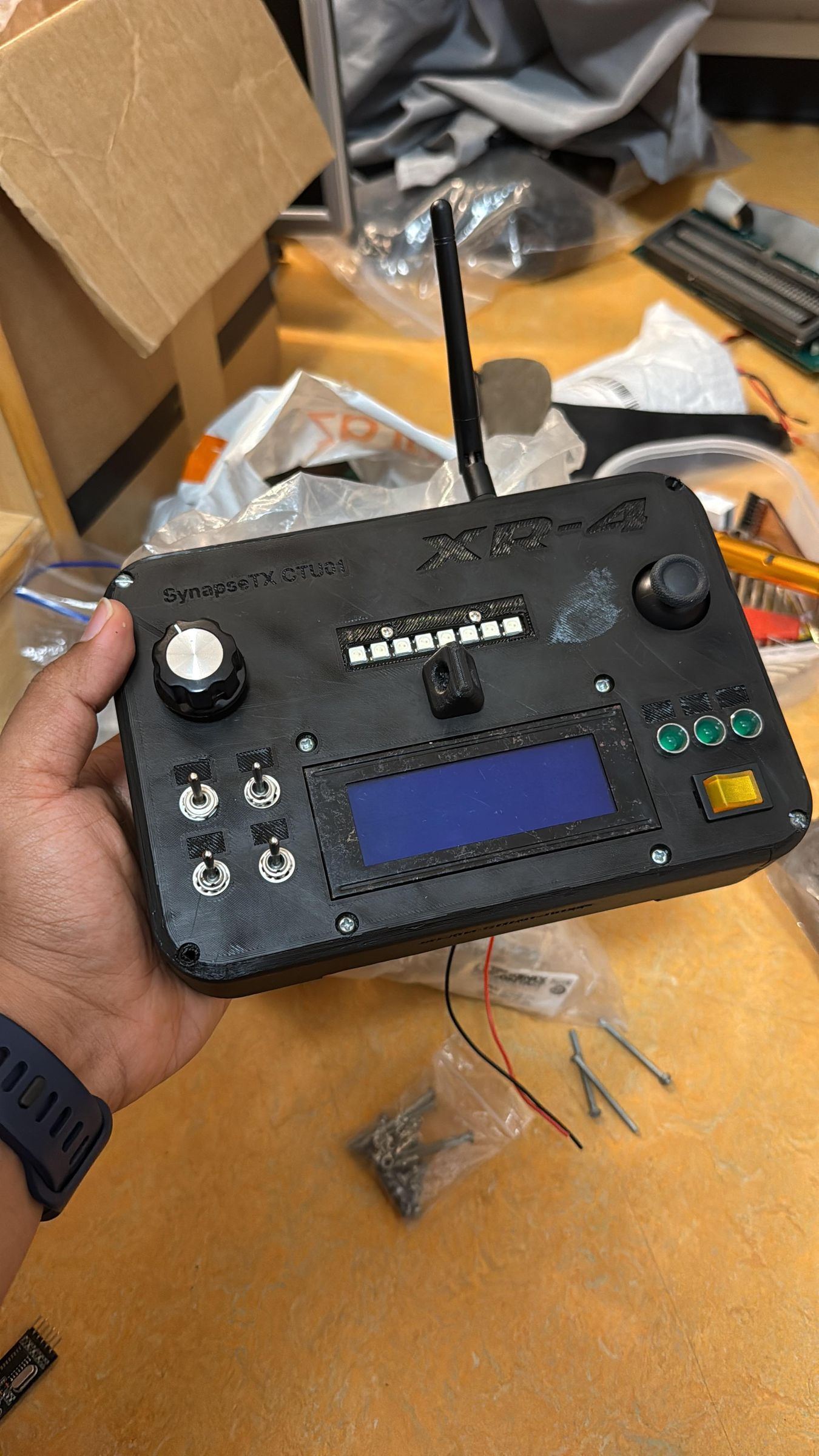
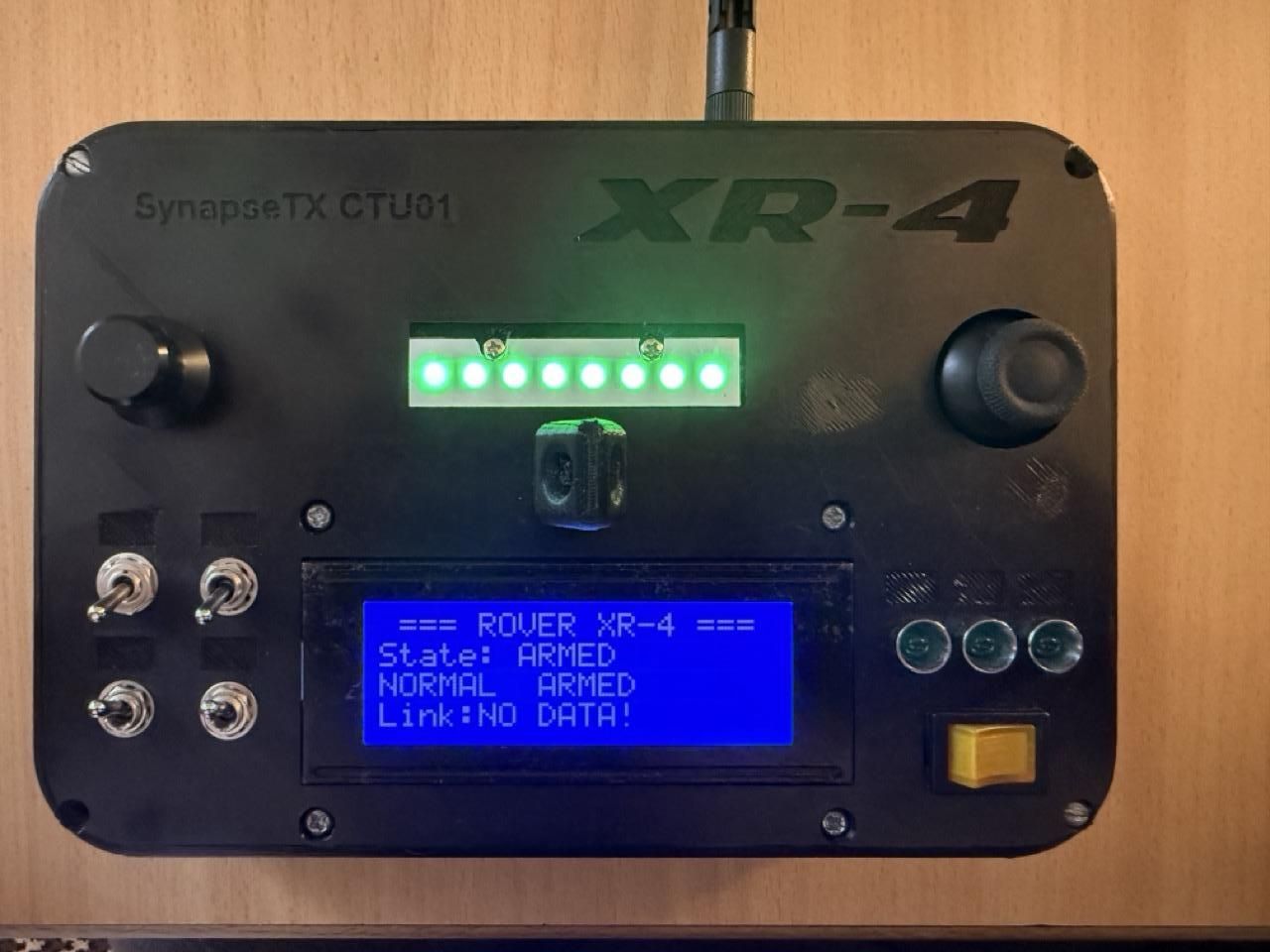
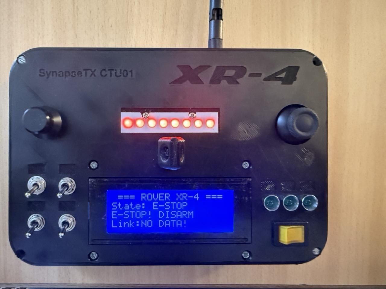
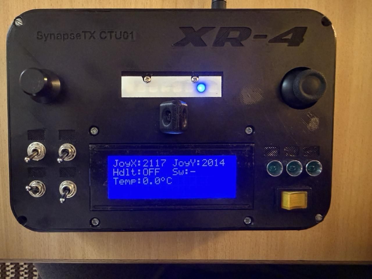
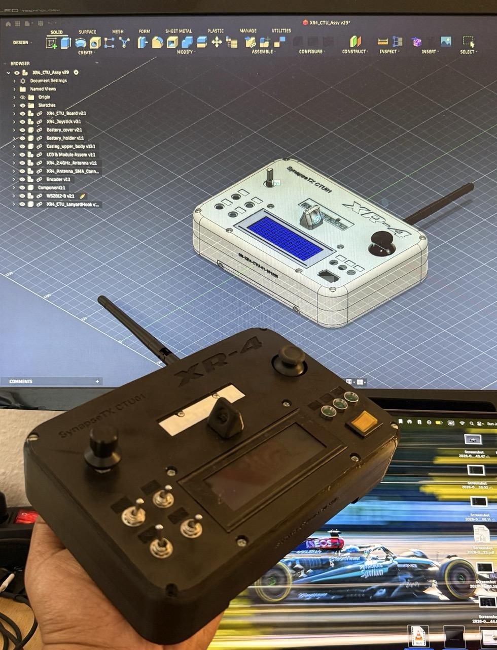
The Control & Telemetry Unit is the hand controller that the operator can use to manually drive the rover. It is the primary user-facing, real-time controller. Since this rover is intended as a testbed for developing autonomous driving and navigation/SLAM in the future, the CTU is intended to serve as the backup/emergency override unit which the user can use to take control of the rover in an emergency scenario or in case of failure of the autonomy stack. The structure of the CTU is 3D printed and was designed in Fusion 360.
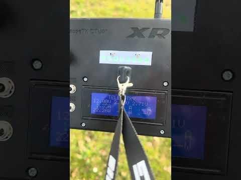
The CTU runs on an ESP32-WROOM-32U Dev Board with an external antenna and uses the ESP-NOW protocol to communicate with the rover's OBC. It has one joytick which is used for both forward/backward and right/left movement, a rotary encoder for navigating through the screens on the LCD, 4 toggle switches for headlights, arm/disarm, E-STOP and a 3-way switch which does not have any function assigned to it at the moment. There is a 20x4 character LCD and an 8-bit WS2812 RGB LED strip to display information about the status of the rover. Three additional indicator LEDs are connected but also do not have any assigned function yet.
Except for the hardware components mentioned above, the CTU is entirely software-defined and a huge number of functions and capabilities can be added to it by firmware updates. The firmware is contained within the GitHub repository mentioned in the Software section.
The CTU is powered by a 2S 1050mAh LiPo, with a TRACO POWER TSR-2450 DC/DC buck converter to provide the +5V needed. The battery needs to be removed for charging unfortunately, since it requires a LiPo balance charger.
The RGB LED strip can be used to display a variety of information and states, currently it has 3 main states, several other states will be added in the future.
- BLUE / SCROLLING: Rover is Ready and Waiting for Arm
- RED / BLINKING: Rover E-STOP Engaged
- GREEN / SOLID: Rover is Armed and Operating
The rotary encoder on the CTU can be used to navigate the different screens on the LCD. The following data is available:
- HOME
- Rover State
- E-STOP State
- ESP-NOW Link Status
- TELEMETRY
- Main Bus Voltage, Current draw and Power draw
- +5V Bus Voltage, Current draw and Power draw (TBA)
- Additional bus (TBA)
- GPS
- Fix status
- Latitude, Longitude
- Time
- IMU
- Compass Heading
- Pitch
- Roll
- INPUTS
- Joystick X & Y values
- Headlight ON/OFF
- Aux. Switch States (TBA)
- Rover onboard temperature
- DIAGNOSTICS
- Packets received from rover
- Packets sent to rover
- Failed Packets
- Uptime
Assembly:
The lanyard hook is optional and can be pressed into the two holes on the top of the enclosure and can be secured using 2x M2 screws
The LCD can be secured to the enclosure using M3 Screws and Nuts.
The Joystick can be secured using M2.5 screws
The CTU Board can be secured to the top section of the housing using M2.5 screws and nuts
Once everything is in place and tested for short/open circuits, the two halves of the CTU enclosure can be secured using M2.5 Screws and Nuts that are around 45mm long.
Final Assembly
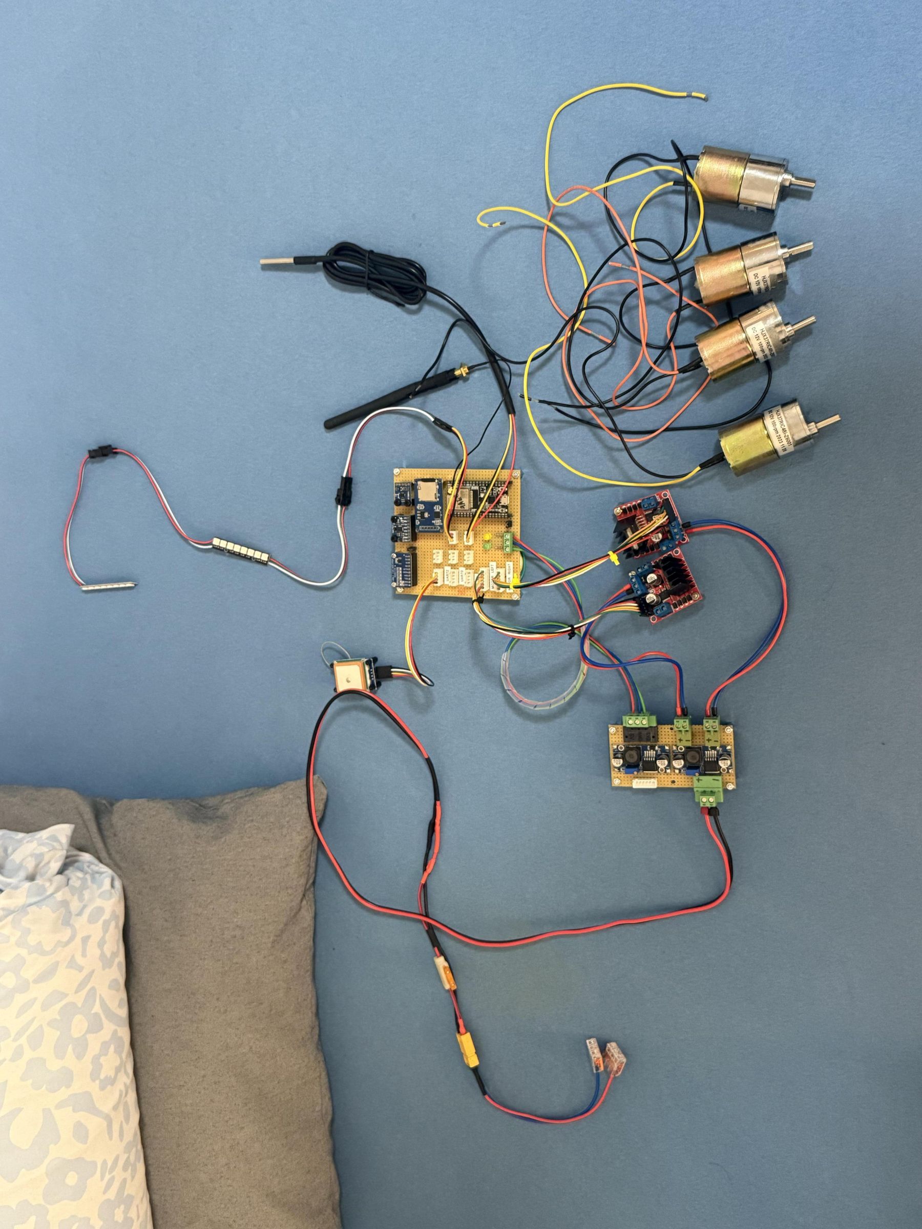
.jpeg)
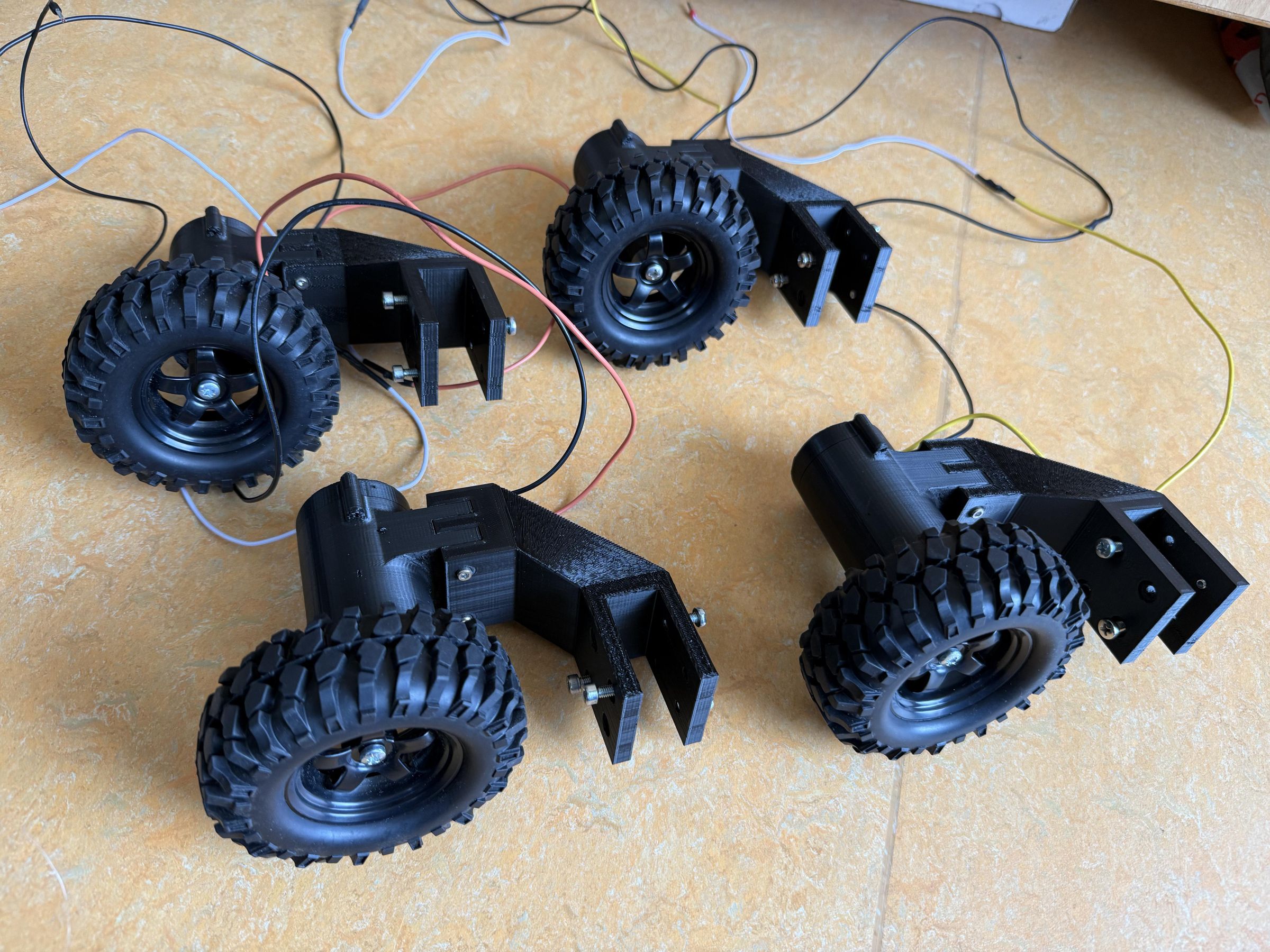
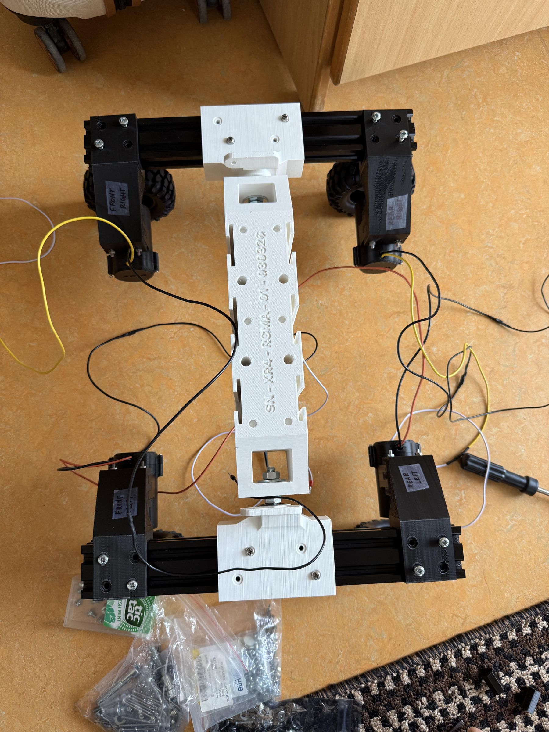
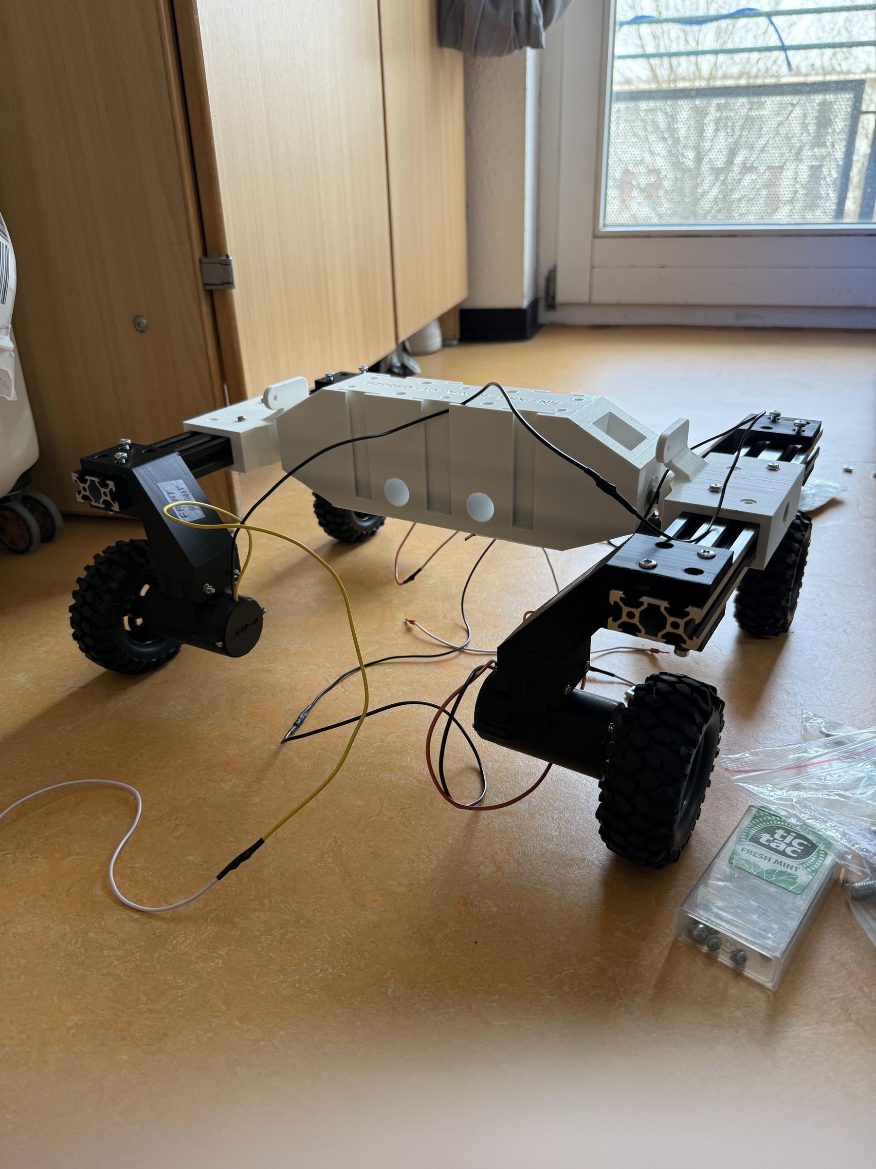
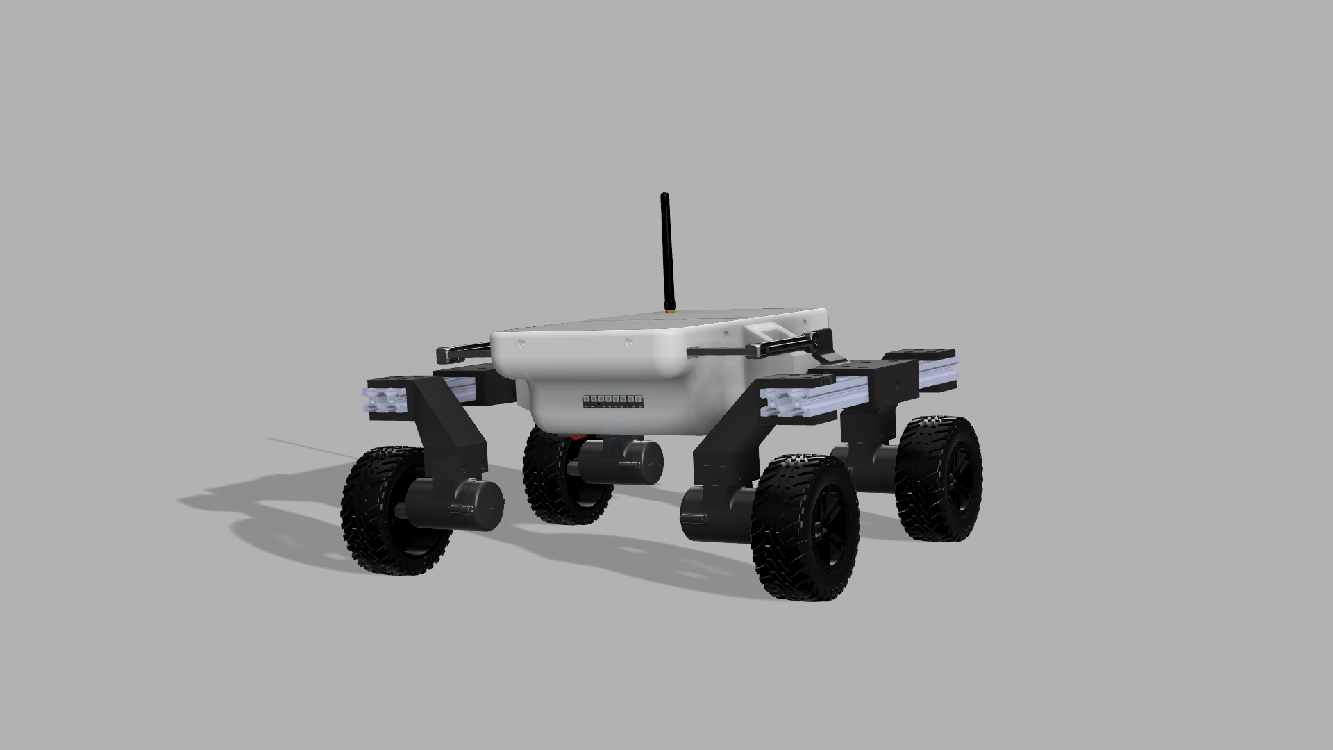
The final assembly of the rover structure is pretty straightforward and I was very happy to see that everything fit perfectly without any tolerance issues etc. All screw holes were of the correct size and the slide-in rails of the front and rear sections had perfect tolerance. Even the cutouts for the power switch and RGB LED strips were perfectly sized. I realized that the time I had spent in double-checking everything had been worth it.
I do not have a step-by-step assembly guide but I can list the steps in the sequence that I followed.
- Insert the motors in the motor casings and secure them using M2 screws (2-3 screws per motor). Repeat for all 4 motors.
- Insert the motor shaft into the cavity on the hex-shaped shaft-wheel adapter, it should be a tight fit. Repeat for all 4 motors.
- Put the motor cables through the motor casing end cap holes
- Secure the motor casing end caps using M2 screws
- Fit the motor casings into the M-shaped joint of the motor struts and align the screw holes and use the mentioned screws and nuts to secure them. Repeat for all 4 motors to get 4 motor casing & strut assemblies.
- Insert the M8 bolt through the hole on the side of the rocker pivot and through the bearing and tighten it. Do it for both rocker pivots.
- Insert the extruded aluminum profiles through each of the rocker pivots, align them so that they protrude equally from the front and back of the rocker pivot
- Secure the aluminum profiles to the pivot using 4-8 M4 screws and T-slot nuts on each side
- Fit the wheel struts at the ends of the aluminum profiles on each of the rocker arms - they should be in pairs (i.e. the Left Front and Right Rear should be the same and the Right Front and Left Rear should be the same) - label them as such and mount them accordingly
- Secure the motor and strut assemblies to the rocker arms using 4-8 M4 screws and T-slot nuts on each strut (there are screw holes on the top and bottom of the "C" shaped cavity of the struts.
- Join the two complete rocker arms to the center section by inserting the nuts into the holes on the sides of the center section with M8 washers on both sides of the holes. Tighten the M8 nuts on both sides.
- Align the slide rails of the front and rear sections with the corresponding sides of the central section and slide them in. You will face some friction but it should slide in. No screws need to be tightened.
- With this, the main structural components are all in place. It is now time to install the electronics inside the rover.
- You can start with running the main bus cables from the front compartment to the rear through the holes passing through the center section.
- Install the RGB led strips for the headlights and the rear lights in the front and rear sections respectively and run their wires to the rear compartment
- Install the main power switch in the cutout in the front section
- Insert the motor cables through the holes on the bottom of the center section and run them to the rear compartment
- Connect the main bus cables to the PDB, connect the 5V and 3.3V bus cables to the OBC, connect all sensors and external peripherals according
- Test all the buses for short circuits and/or open circuits
- If everything is good, connect the battery and turn on the power switch
- Turn on the CTU, it should connect to the rover's OBC ESP32 over ESP-NOW almost immediately. If the connection is unsuccessful, you will see NO DATA! on the CTU screen
- The rover should power up in the WAITING FOR ARM state and the rear RGB LED strip on the rover and the CTU RGB LED strip should display a scrolling blue pattern.
- Move the ARM switch to the ARMED position, the status should update on the LCD and the RGB LED strips should be a solid green
- Move the controls forward/backward/left/right and see the rover move!
- Congratulations :) !
Drive!
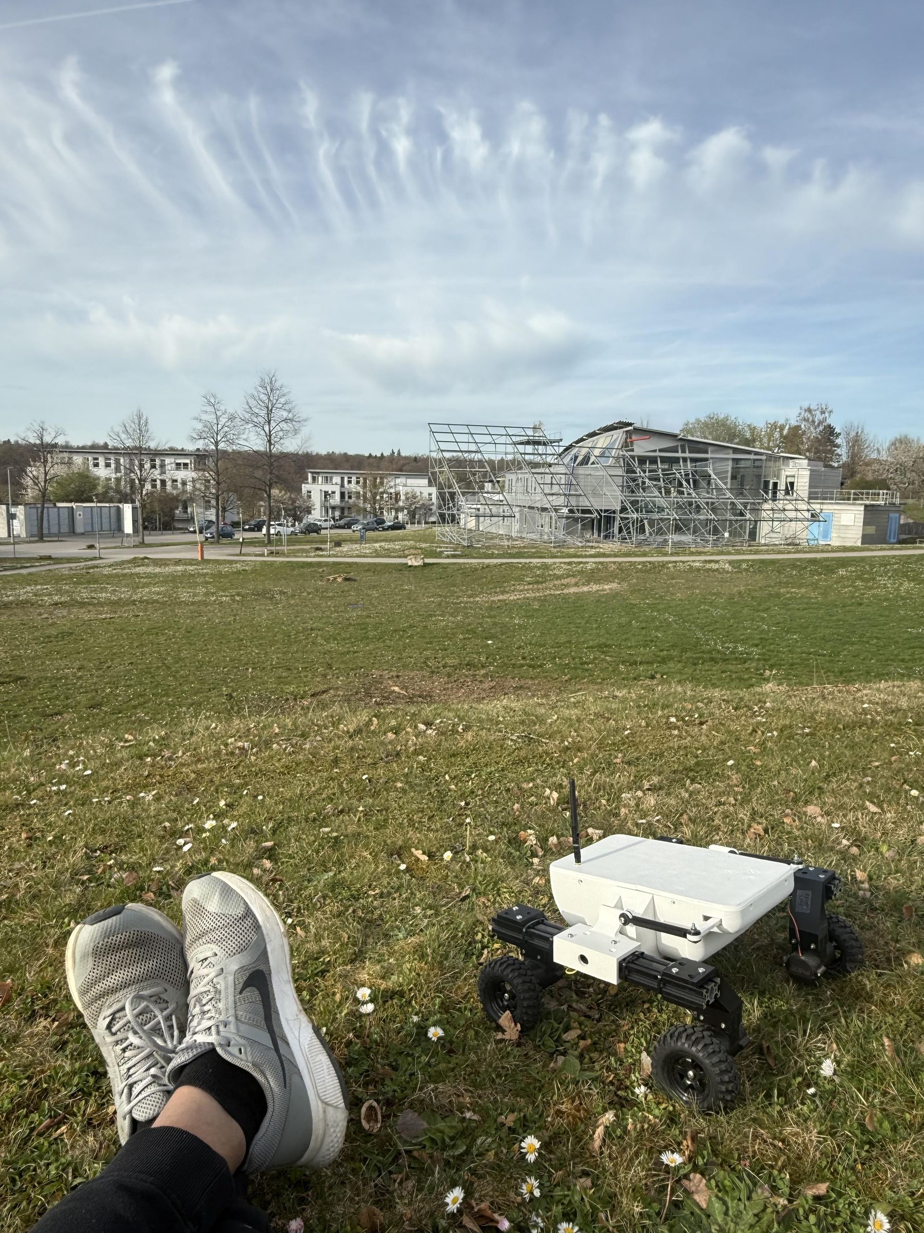
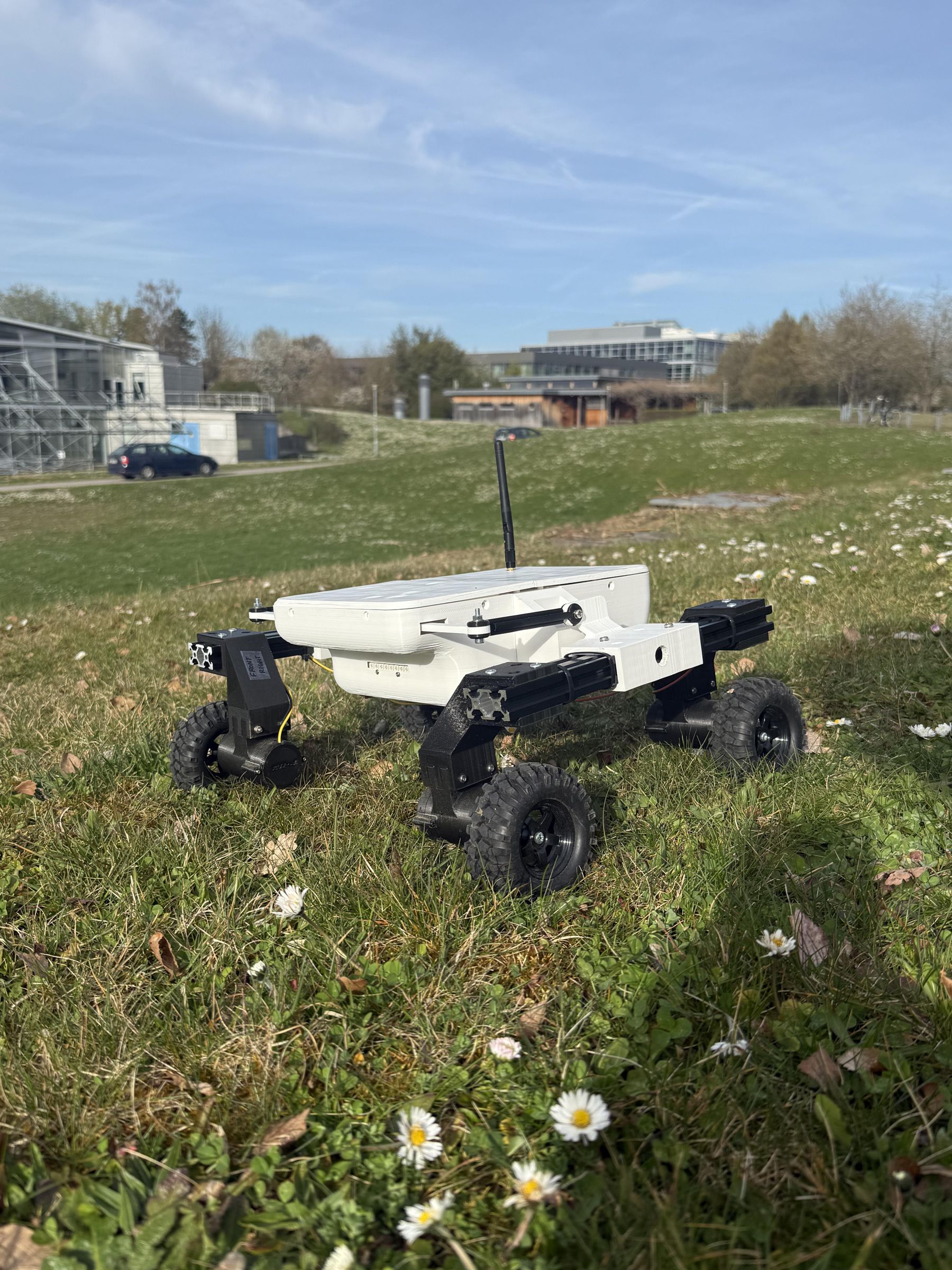
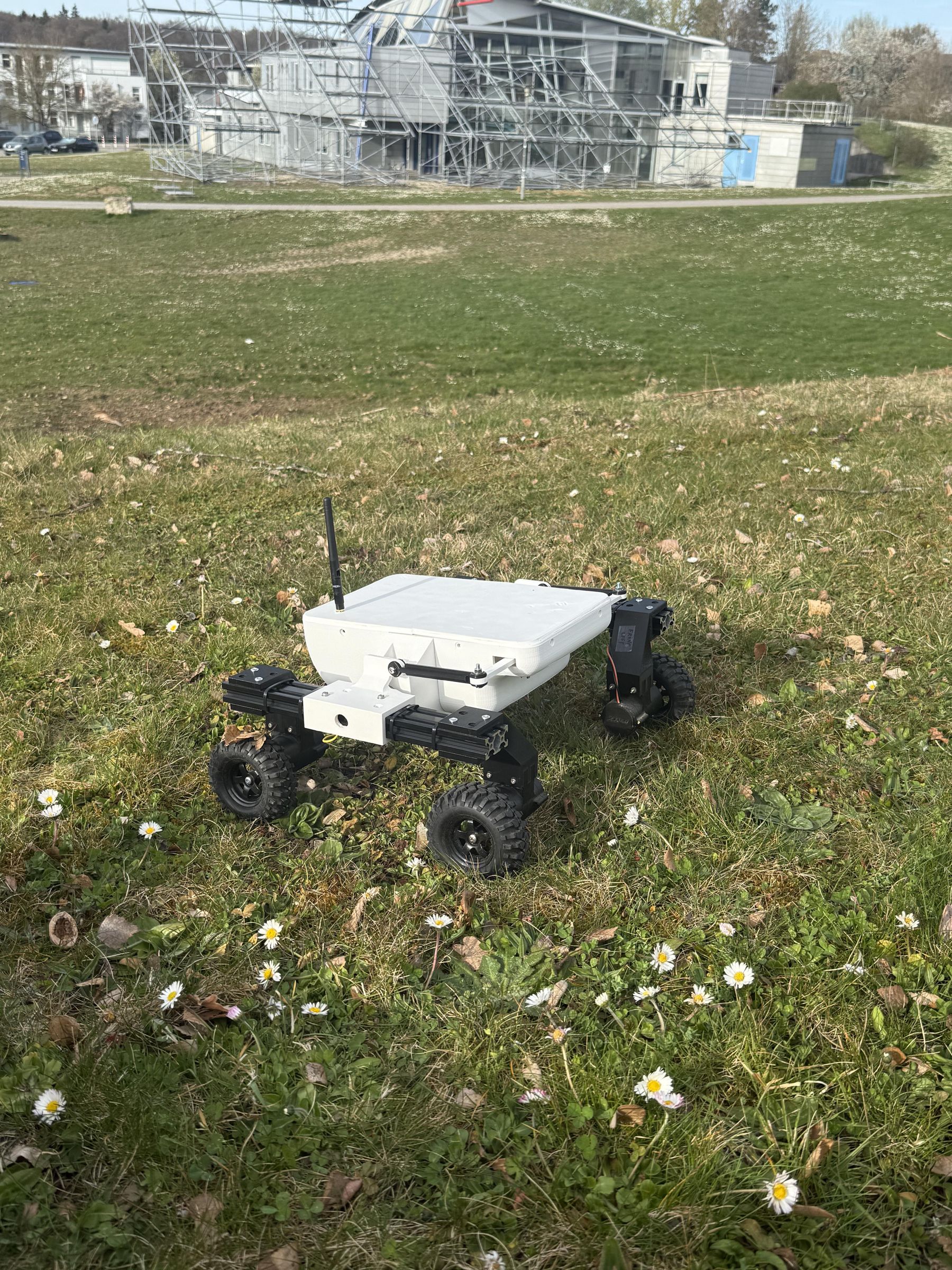
With the assembly and benchtop tests complete, it was time to take the rover out for a spin.
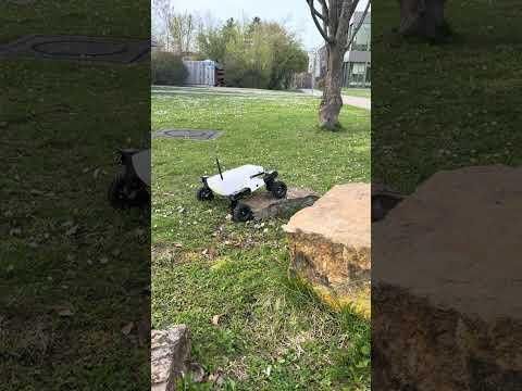
All systems were go on a sunny weekend with beautiful weather. I had the rover climb steep slopes, drive over tree stumps and uneven terrain as well as normal gravel tracks. It drove and handled beautifully. It maneuvered steep inclines, up to 40 degrees, and did not break a sweat on uneven terrain or large obstacles.
With 100RPM geared motors, the torque is immense and the rover handles loads and friction extremely well. The differential drive implementation causes lateral loads on the wheels - this is more than expected due to the rover being heavy and the wheels being much softer than expected. As a result, the wheels have a large area in contact with the ground, adding to the friction which causes lateral loads on the pivoting wheel during tight turns. This is something that I intend to work on, both algorithmic changes to the differential drive implementation in software and hardware modifications in the shape of stiffer tyres will have to be done.
However, for now, the rover drives like a dream and I couldn't be more happy or proud at this accomplishment. This project was a personal challenge and it has provided me great insight into managing and developing complex projects, as well as valuable technical insight and practical experience into real-time motor control, low-latency telemetry & telecommand handling, sensor integration, as well as CAD and 3D printing. I feel confident now of undertaking even more complex projects.
I hope that you will like this project and find it worth your time to build one. I can guarantee that you will enjoy building and modifying/improving it. I did :)
Please give me your feedback and comments. If there are any problems and discrepancies, I will be very happy to help you. I look forward to seeing you build this. All the best!
I am sharing a link to a Google Drive folder containing videos of the rover. I don't have a YouTube channel and didn't want to create one so here it is: Rover XR-4
Acknowledgements and Next Steps
This project would not have been possible without access to the facilities, tools and equipment provided by the StudLab of Faculty 05: Informatik, Elektrotechnik und Informationstechnik of the University of Stuttgart. It is an amazing facility which allows students to work on their projects using the best available tools and equipments, including two 3D printers. I am very grateful to the StudLab Team, a part of the Fachschaft Electroktrotechnik und Informationstechnik (FS-EI) for their dedication in handling the day to day management of the lab and to the patronage of the Dean of Faculty 05.
I am also very grateful to PCBWay and JLCPCB (and JLCCNC) for their offers of sponsorship for PCBs as well as CNC'ed parts. One of the greatest constraints I faced during this project was that of cost - every decision had to be judged on this basis and therefore, limited my options with regards to certain design approaches.
In the next step, I want to accomplish the following technical milestones:
- Develop robust, professional PCBs for the Power Distribution Board, the On-board Computer Board, the Control & Telemetry Unit Board, as well as other smaller boards for various modules (such as power monitoring, external environmental sensing, etc). The offers of sponsored PCBs by JLCPCB and PCBWay will be very useful in this regard.
- Develop stronger and more durable structural parts such as the rocker pivot, wheel struts and motor casings which will reduce weight, increase strength and increase the operational life of the structure of the rover, allowing me to continue using it as a testbed, as well as widening the scope of modifications and upgrades (since all this would increase wear-and-tear and weight, and durable and strong parts are necessary). I am very grateful to the sponsorship offer by JLCCNC in this regard.
- The implementation of a professional autonomous mobile robotics stack with SLAM and autonomy capabilities. This includes the addition of a single-board computer-based high level Mission Computer which will run the SLAM / Autonomy stack and which will integrate with the rover OBC and direct its driving functions. This will involve the integration of a LIDAR, a camera (perhaps a depth camera, which is too expensive for me at the moment) and GPS, IMU and Compass data. Some of the pieces of this system are already in place, some will be added in the future. A main shortcoming, as I see it, is that the motors do not have encoders (this was also a cost decision since I could not afford motors with wheel encoders). However, I am determined to continue developing this platform regardless of the limitations.
- I have already procured the LIDAR (RPLIDAR C1) and will be using an old webcam for the camera. I will be updating the IMU to the MPU-9250 with a built-in compass/magnetometer. This hardware is currently on my desk, awaiting integration with a suitable SBC-based mission computer
- The current roles of the OBC will remain the same, except that it will be directed by the mission computer instead of the user via the CTU. The user will, however, maintain overall override authority.