XRP Autonomous Navigation
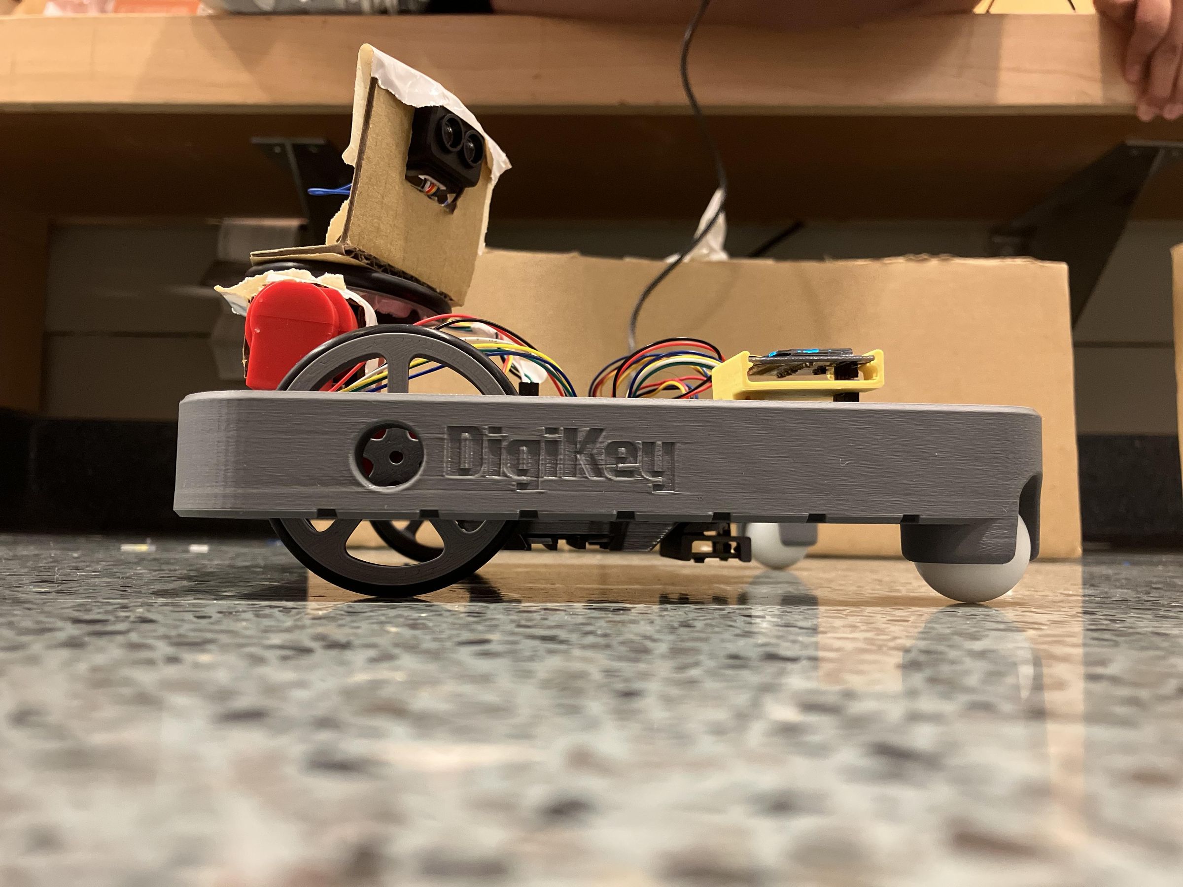
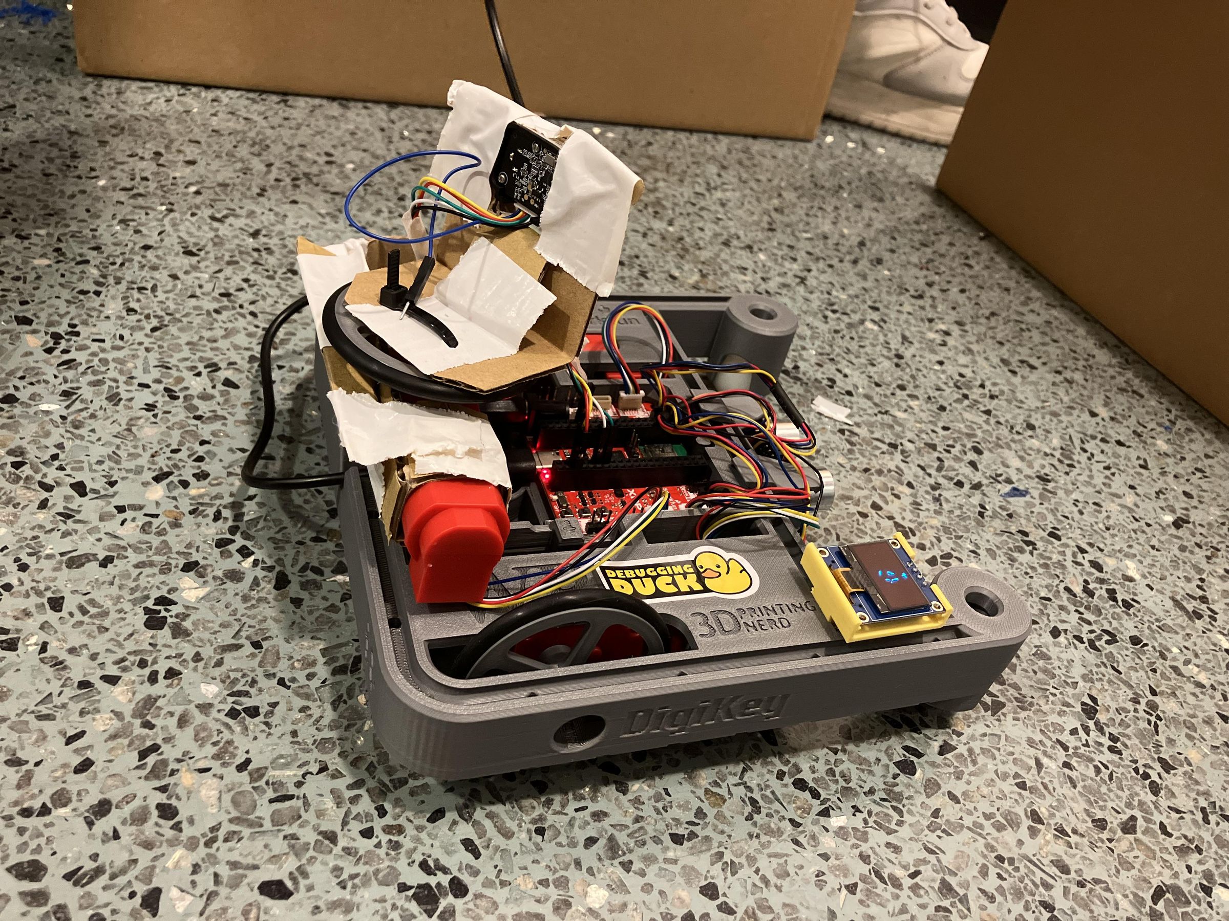
Have you ever wanted to get your robot from point A to point B? What if there was a wall in the way? Lesser robots wouldn't even be able to notice such a wall, let alone avoid it! This perplexing and difficult problem inspired us to create this project, in which we modified the XRP (Experimental Robotics Platform) to give it a 2 dimensional, 360 degree lidar. Now that we knew where the wall was, we still needed to navigate our way around it. For this we implemented an A* pathfinding algorithm to efficiently determine a path around the obstacle, and to sweet, sweet victory. (Reasonable speed not guaranteed)
In this guide, we will provide steps to build and program one of these yourselves, for all your pathfinding needs!
Disclaimer: The video is sped up in the middle portion while the robot is thinking.
Downloads
Supplies
- Main:
- 1x XRP robotics kit
- Lidar:
- 1x Sparkfun Hobby Motor With Encoder (in addition to the two already in the kit)
- 1x Extra wheel for the extra motor (can be substituted for anything that fits onto the shaft of the motor, even tape, at your own risk)
- 1x T-F Luna Lidar Sensor (any distance sensor can theoretically be used, but some are better than others)
- Cardboard
- Tape (Duct tape or similar)
- 2x zip ties (Can be substituted for more tape, at your own risk)
- OLED Display (optional, but cool and helpful)
- 12864 128X64 OLED LCD Display Board Module I2C IIC SSD1306
- 1x 3D-printed mount: https://www.thingiverse.com/thing:6669383
- Flexible Qwiic Cable - Female Jumper (4-pin)
OLED Display Assembly
![PXL_20260801_193129046[1].jpg](/proxy/?url=https://content.instructables.com/FSN/ZC0G/MS6P2GTT/FSNZC0GMS6P2GTT.jpg&filename=PXL_20260801_193129046[1].jpg)
![PXL_20260801_193214070[1].jpg](/proxy/?url=https://content.instructables.com/FBS/S1PR/MS6P2GTW/FBSS1PRMS6P2GTW.jpg&filename=PXL_20260801_193214070[1].jpg)
![PXL_20260801_193029418[1].jpg](/proxy/?url=https://content.instructables.com/FHD/A2BC/MS6P2GTQ/FHDA2BCMS6P2GTQ.jpg&filename=PXL_20260801_193029418[1].jpg)
- Solder the 4-pin header to the OLED module printed circuit board. The long side of the pins stick out from the bottom side of the module (The OLED display is on the top side.) If the pins are already soldered, you can skip this step.
- Print the 3D printed mount for your OLED display.
- Connect QWIIC connecter head of the QWIIC cable to the QWIIC 1 port on the main board of your XRP robot.
- Connect the jumper cable heads of the QWICC cable to your OLED display. The ordering of the cables is
- Black - GND
- Red - VCC
- Blue - SDA
- Yellow - SCL
- Clip the OLED display into the 3D printed with the cable located inside of the notch in the model. If the cables don't fit, whittle the notch to be wider.
- Download the separate SSD1306 library for the OLED display here https://drive.google.com/file/d/1plSaRPhqN2uv6CT4Ds6KC_ggsLL802d-/view.
- Import the library onto your XRP robot and run the test code to make sure everything works properly.
Motor Mount
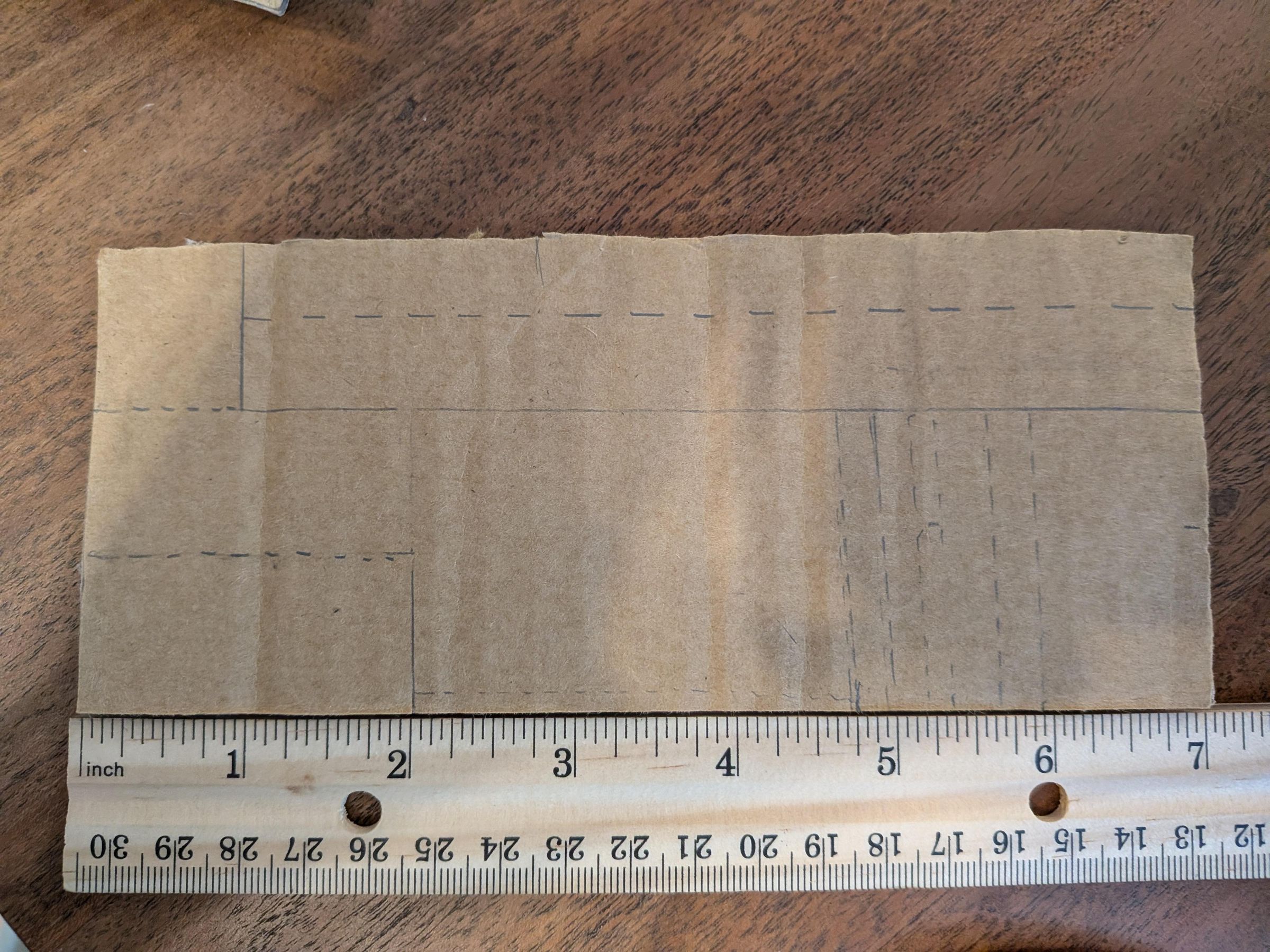
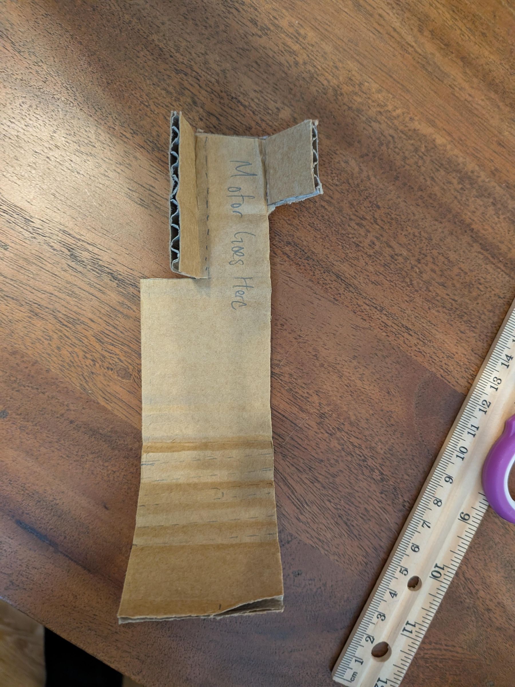
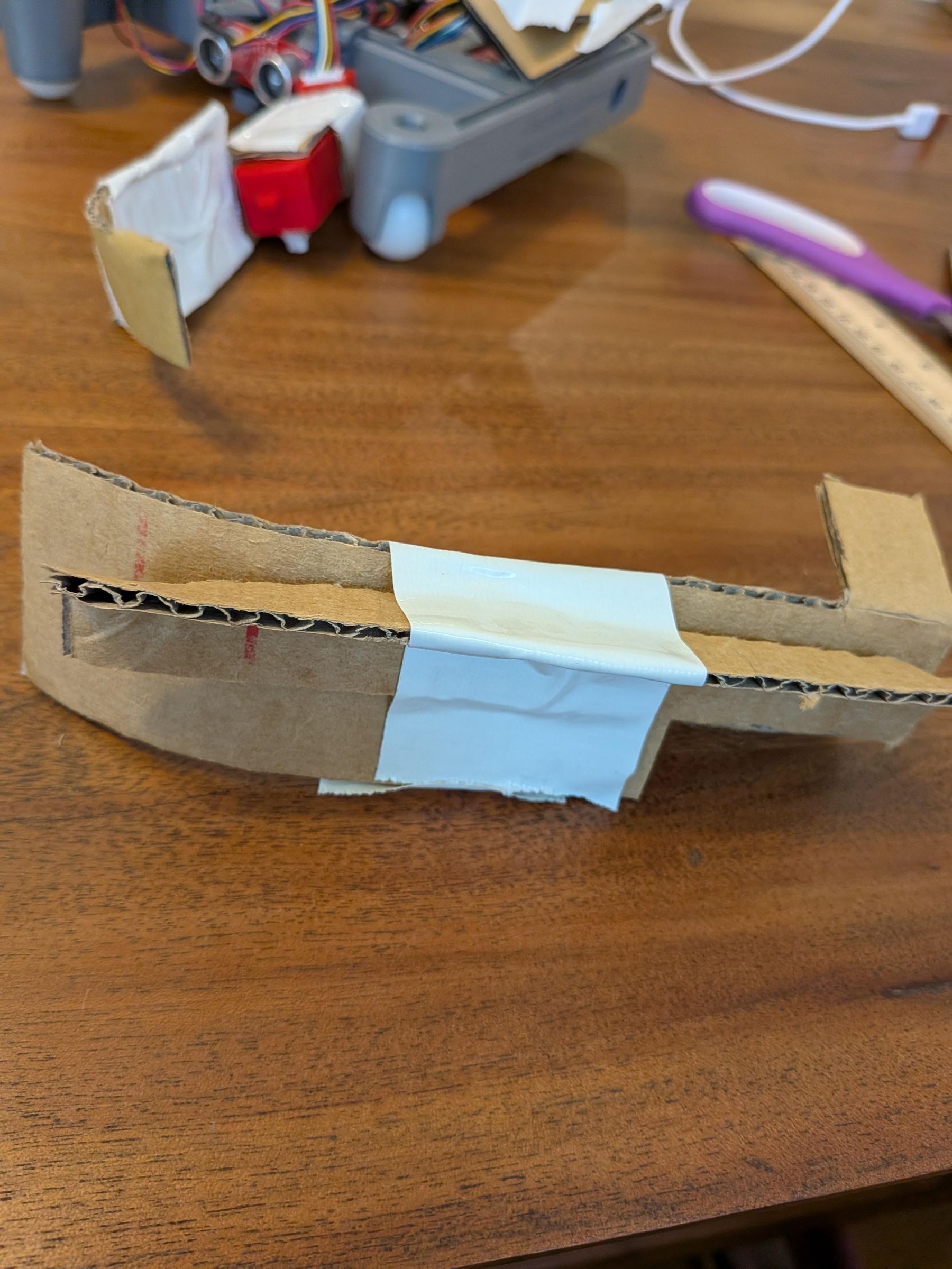
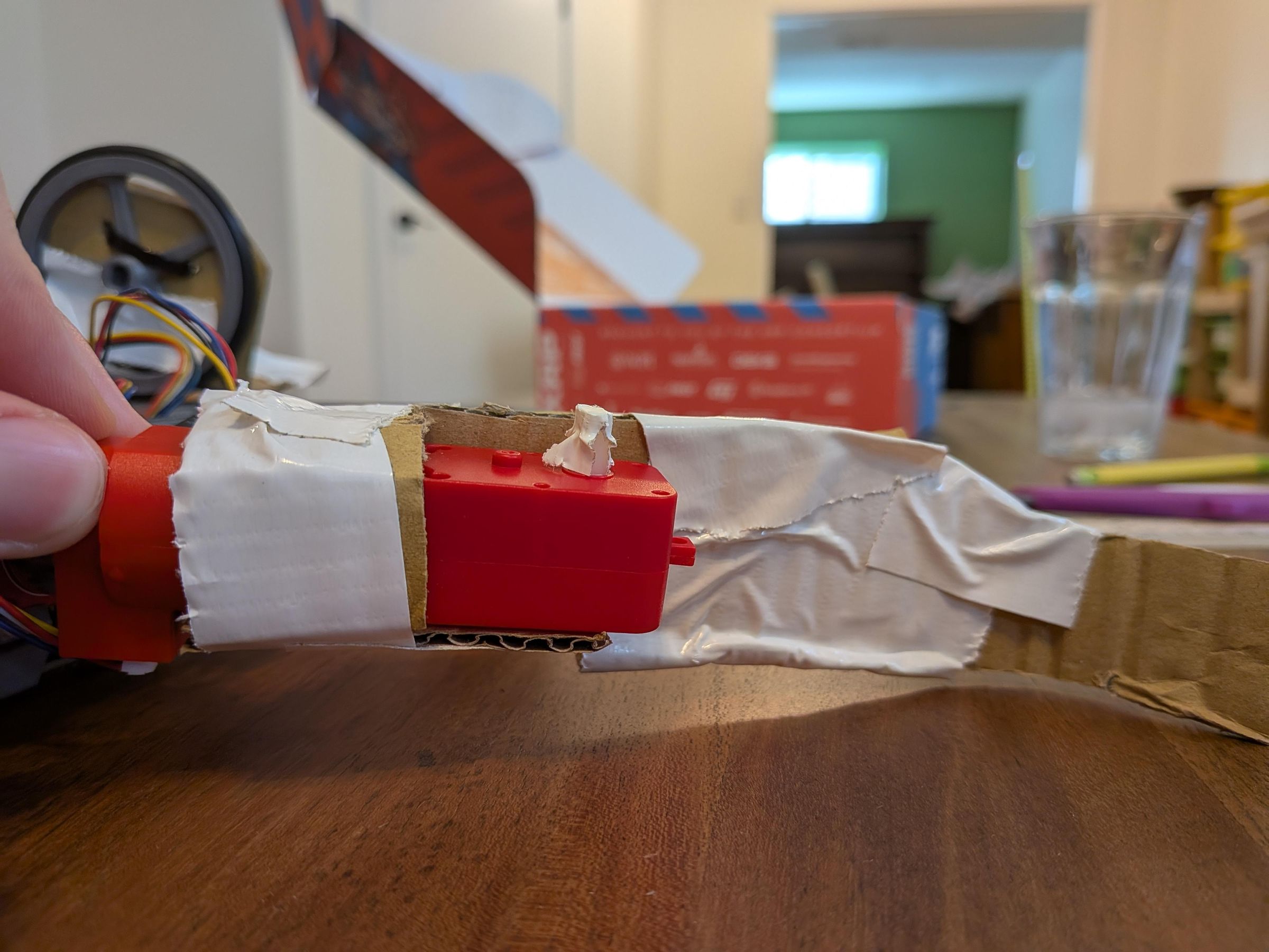
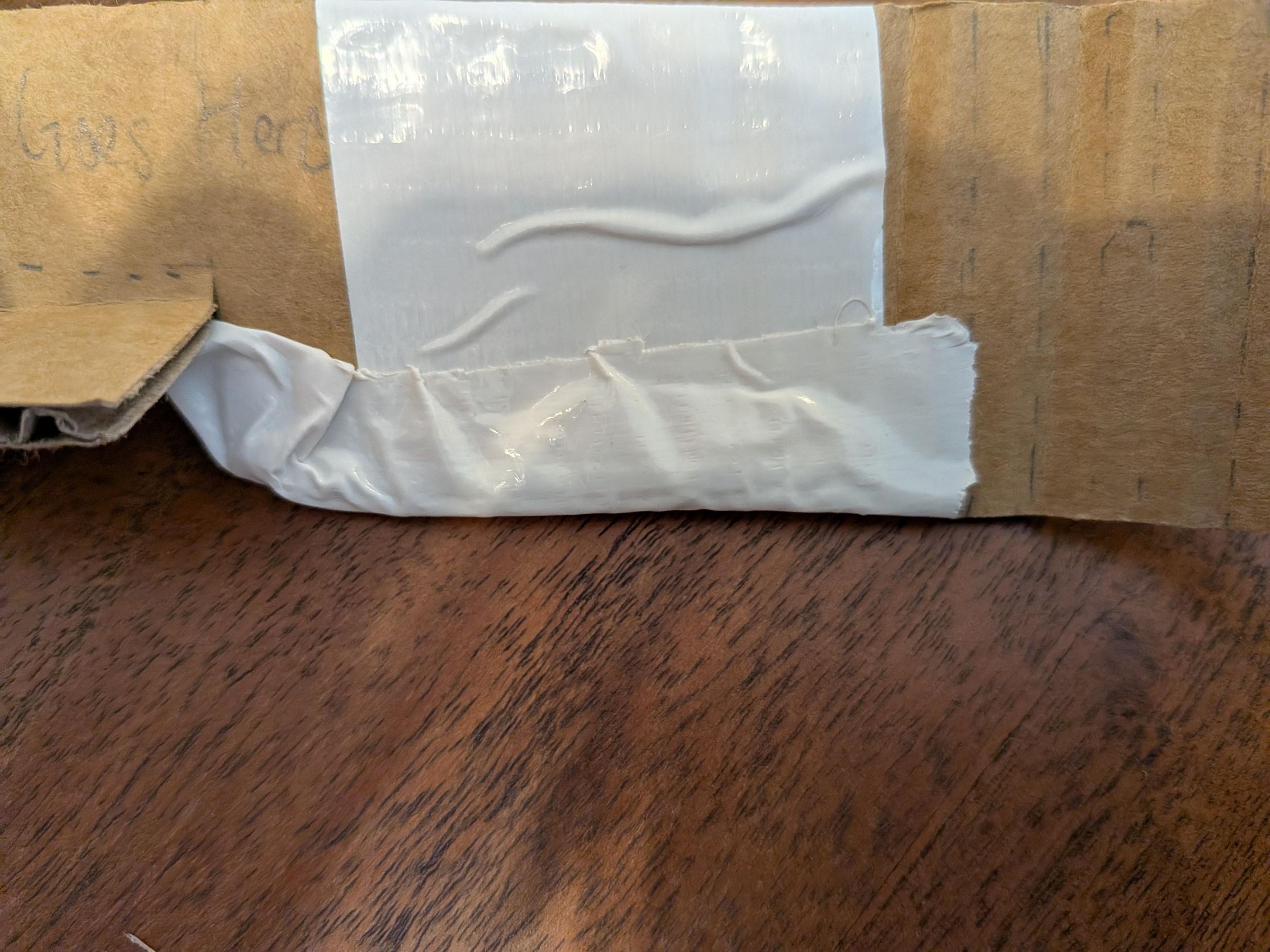
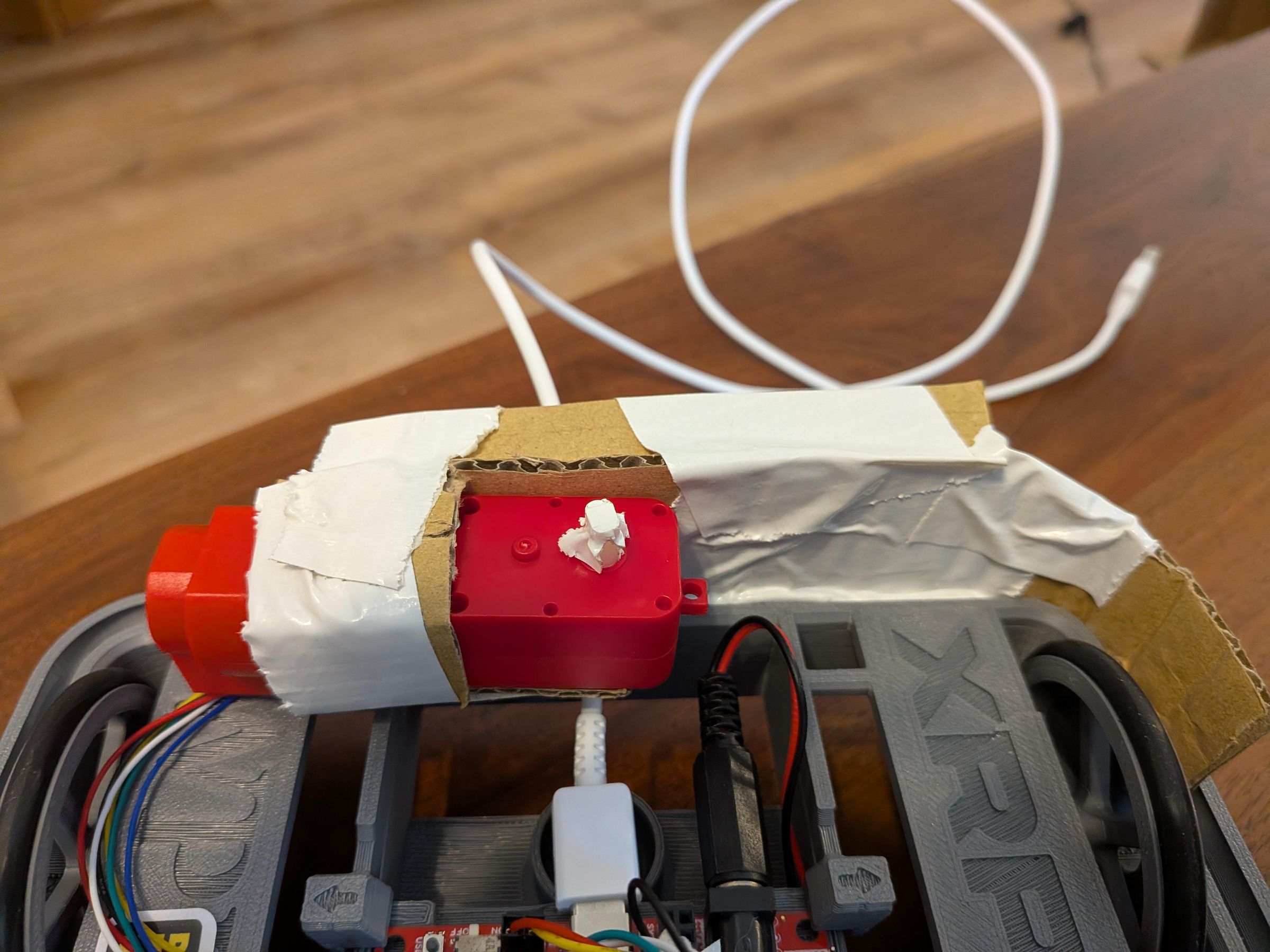
In the name of accessibility (And laziness) The motor mount is not 3d printed. Instead, it is made out of cardboard. If anyone would like to make a 3D printed version however, please share it with us!
- Cut a 3 inch by 7 inch cardboard square
- In the image of the cardboard shown above, cut this 3 by 7 inch cardboard square along the solid lines and fold the cardboard remaining along the dotted lines. Your cardboard should look like the image of the folded cardboard attached above
- Take your XRP hobby motor and connect the encoder cable to your motor and to motor port 4.
- place your hobby motor in the spot labeled motor goes here in the image of the cut out cardboard. Tape your motor so that the motor is oriented like the motor in the finished image of the motor mount.
- Attach the extra piece of cardboard to the back of the motor mount to provide extra stability as shown in the image of the back of the motor mount
- Scrunch up the bottom of your motor mount and tape it over as shown in the image of the bottom of the motor mount. This is to ensure that the motor mount fits into the slot on the XRP robot.
- Slot the motor mount into the XRP
Get the Lidar Working
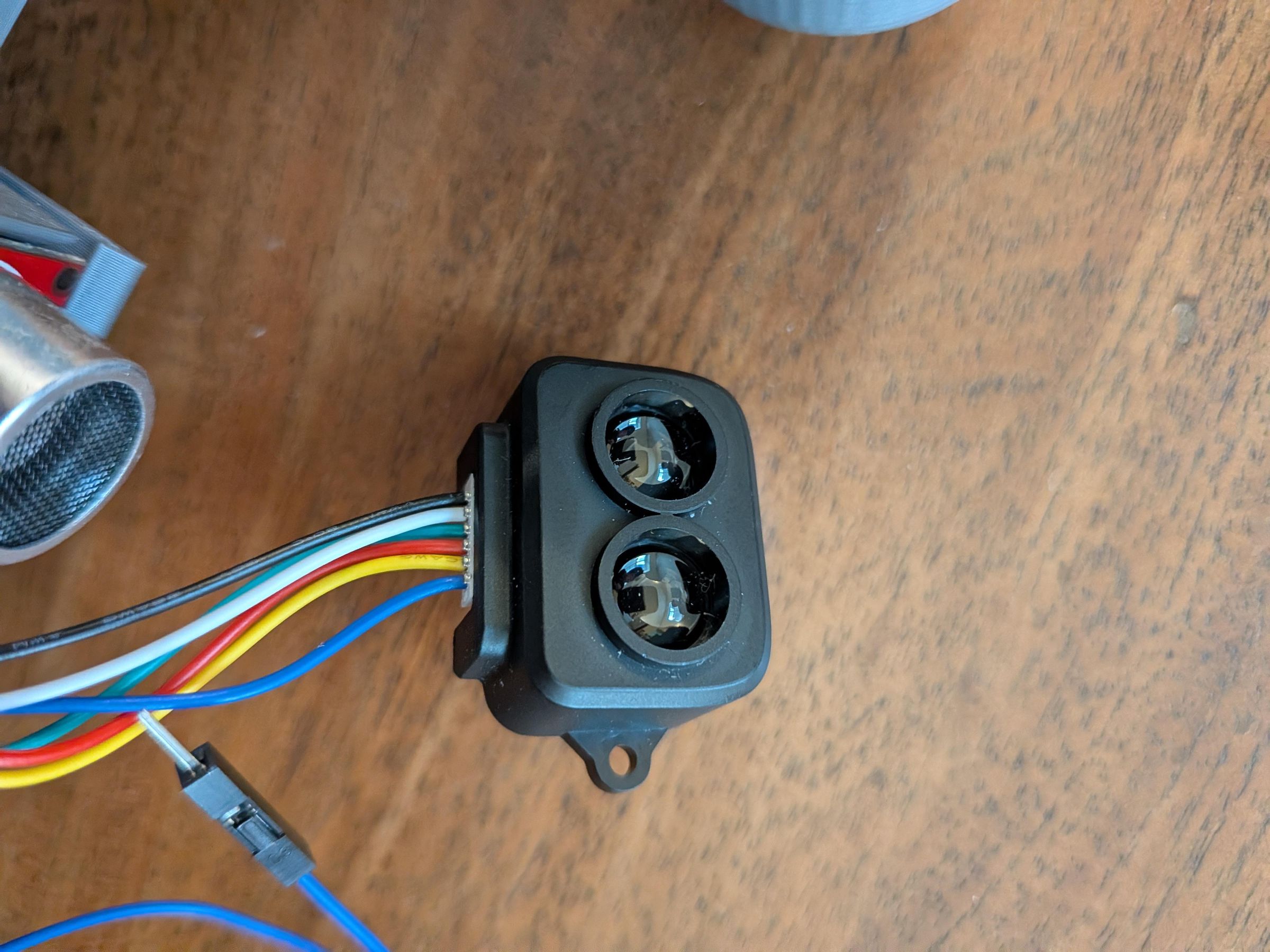

The Lidar is probably the most important part of the build. It lets us get distance measurements to the wall at all angles, and with a little bit of trig, we can plot these points on a cartesian grid, giving us a 2d map of the world around us.
We chose the TF-Luna Lidar because of it's long range, and small field of view. This makes it much more accurate, precise, and reliable than other distance sensors like the built-in ultrasonic. However, that doesn't mean other distance sensors won't work! In fact, if you are willing to spend a lot of time calibrating and are ok with a lot of error, you can get away with just the ultrasonic sensor, and spin the whole robot instead of the fancy lidar mount.
That over, here is how you get the lidar working:
- The lidar comes with 3 cables. You only need to use the one that has male jumper cables on the end of it.
- Attach the encoder head of the lidar to the female encoder port on your TF Luna lidar. The lidar is already preassembled so you only have to connect the wires.
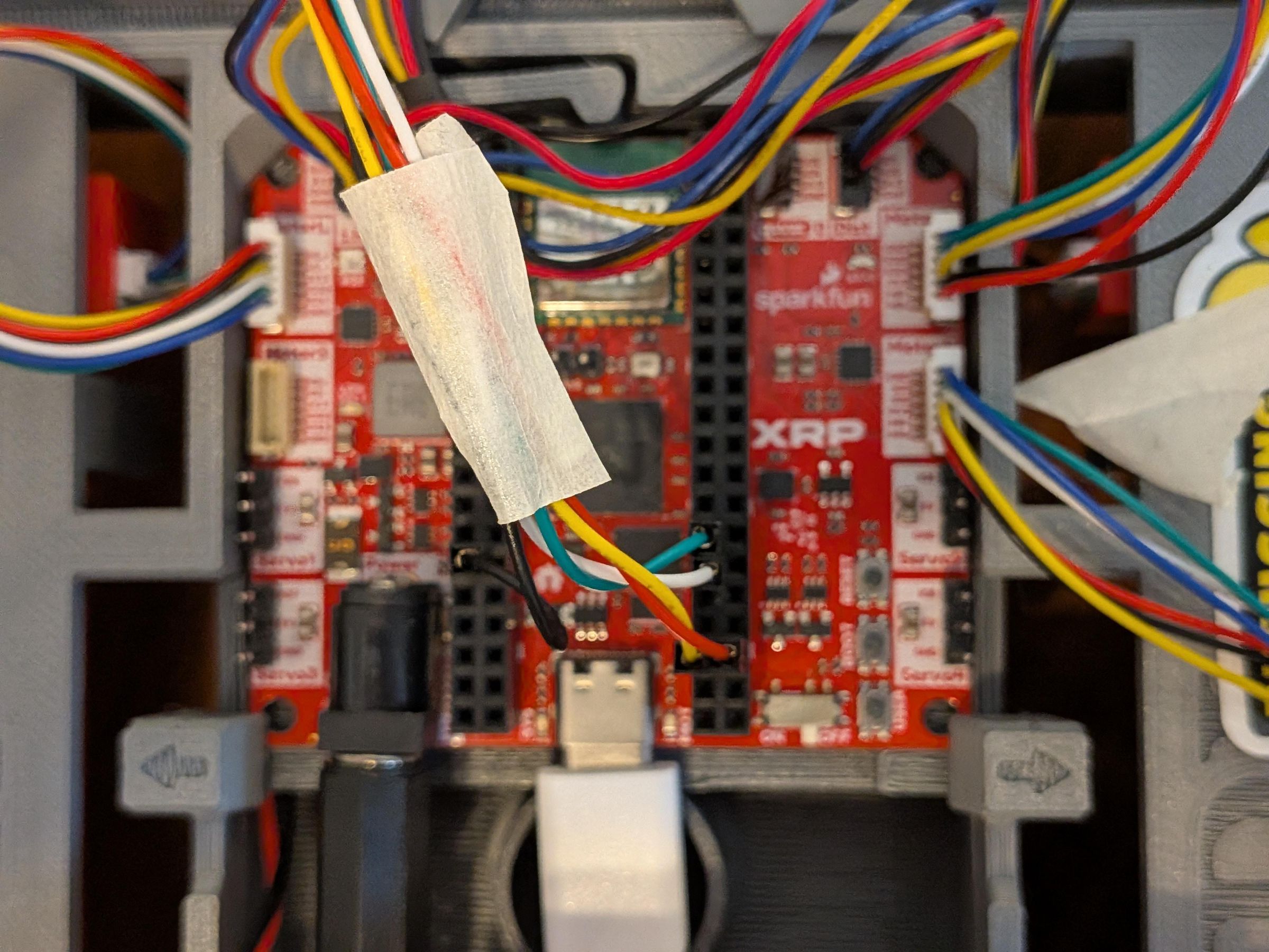
- Connect the male jumper cables to the Female jumper cable ports on your XRP board. Copy the wire arrangement as shown in the photo of the XRP board and the jumper cables. For this XRP, the blue cable is not necessary to connect.
- Download the lidar library from github, and place it in the library folder of the XRP editor.
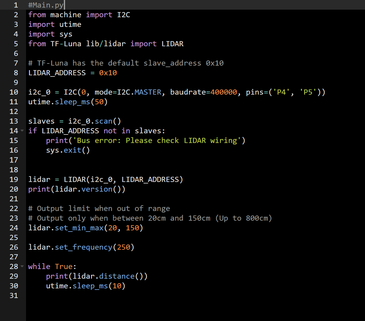
- Switch the 12C ports in the main.py library to p4 and p5, instead of p7 and p8
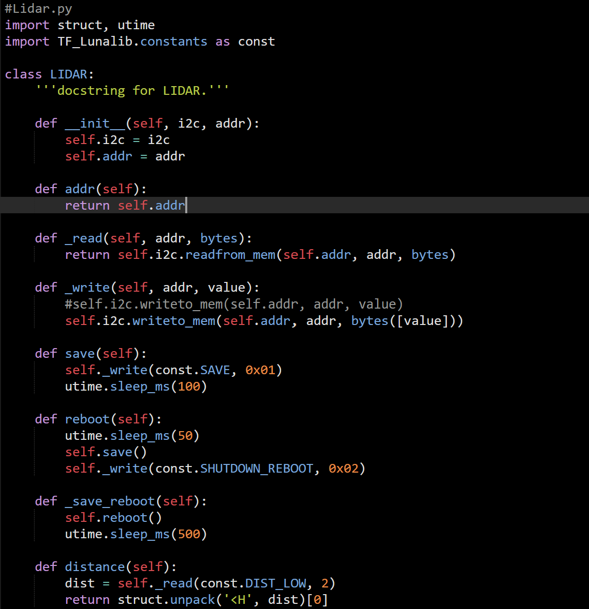
- Run the main.py program. if it works, you are done! otherwise, try to match your files to ours in the images above, as we made some small changes.
- If it still does not work, continue debugging until main.py runs.
You may notice that Pins 4 and 5 are the same pins that run the Qwiik 0 connector. This is because The T-F Luna also uses I2c, but cannot plug directly into the connector due to the fact that it runs on 5v not 3.3v. Also, it would require soldering on a new header for the cable.
So, does it use the Qwiik port? Kinda.
Lidar Mount
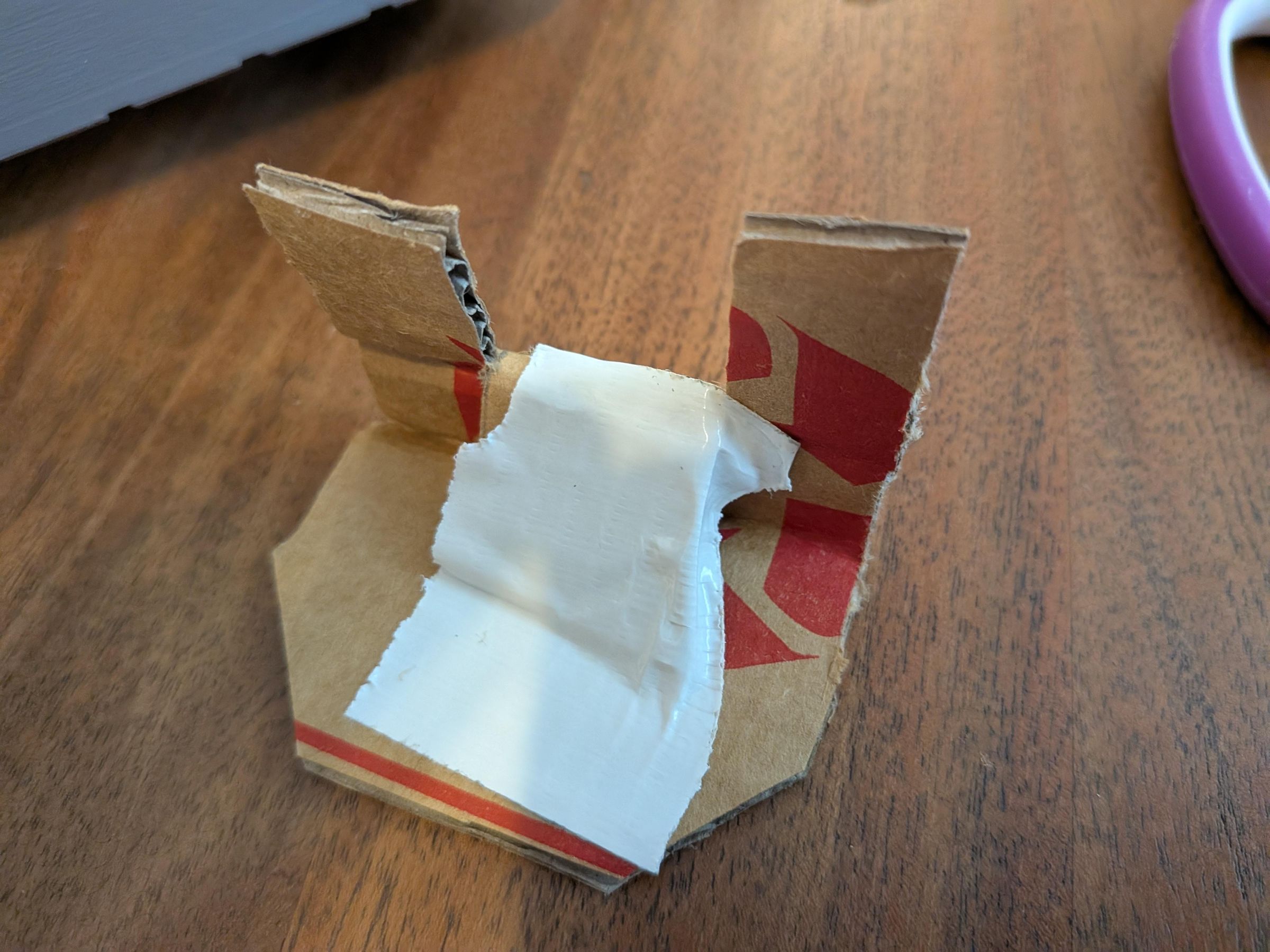
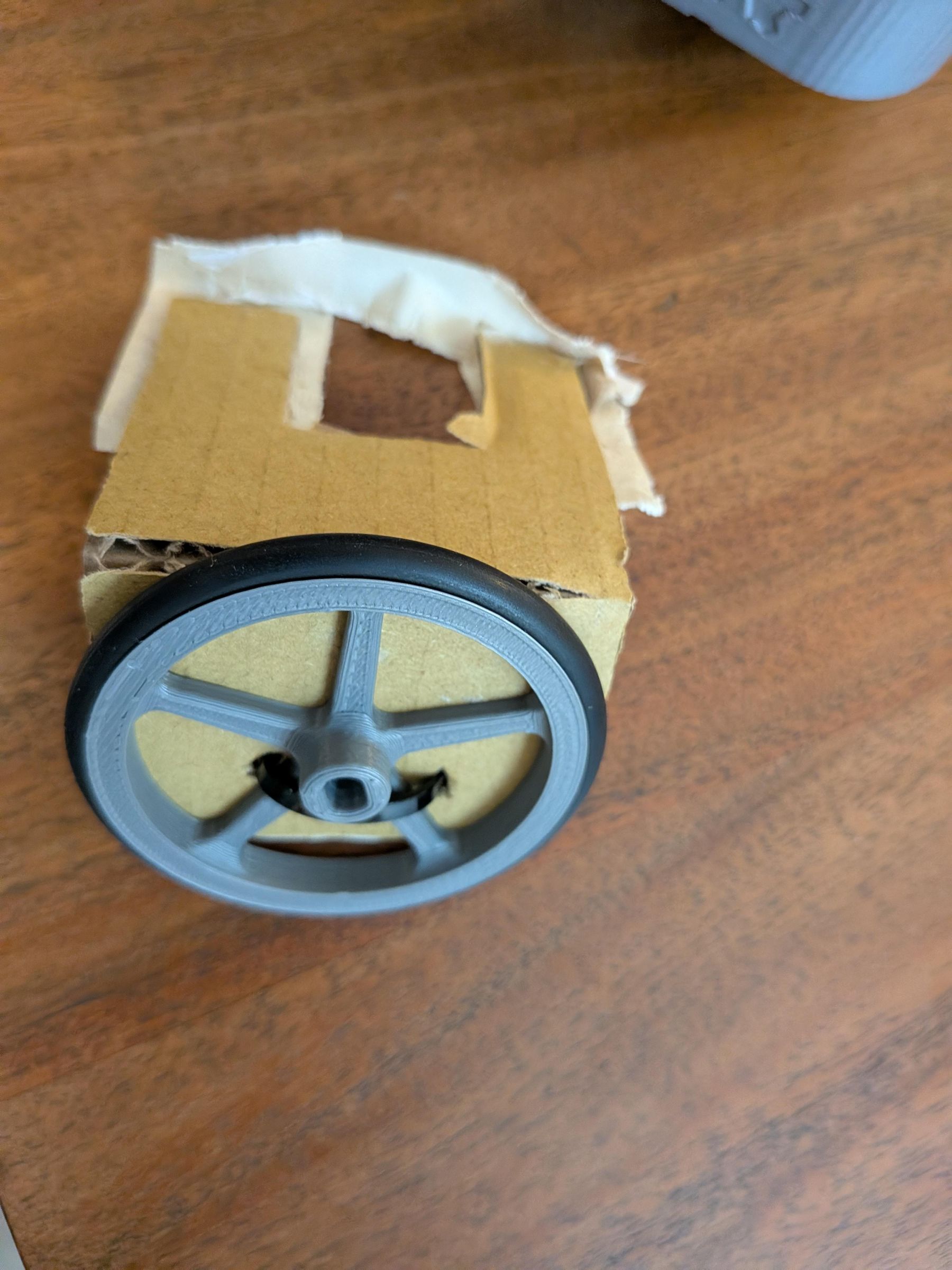
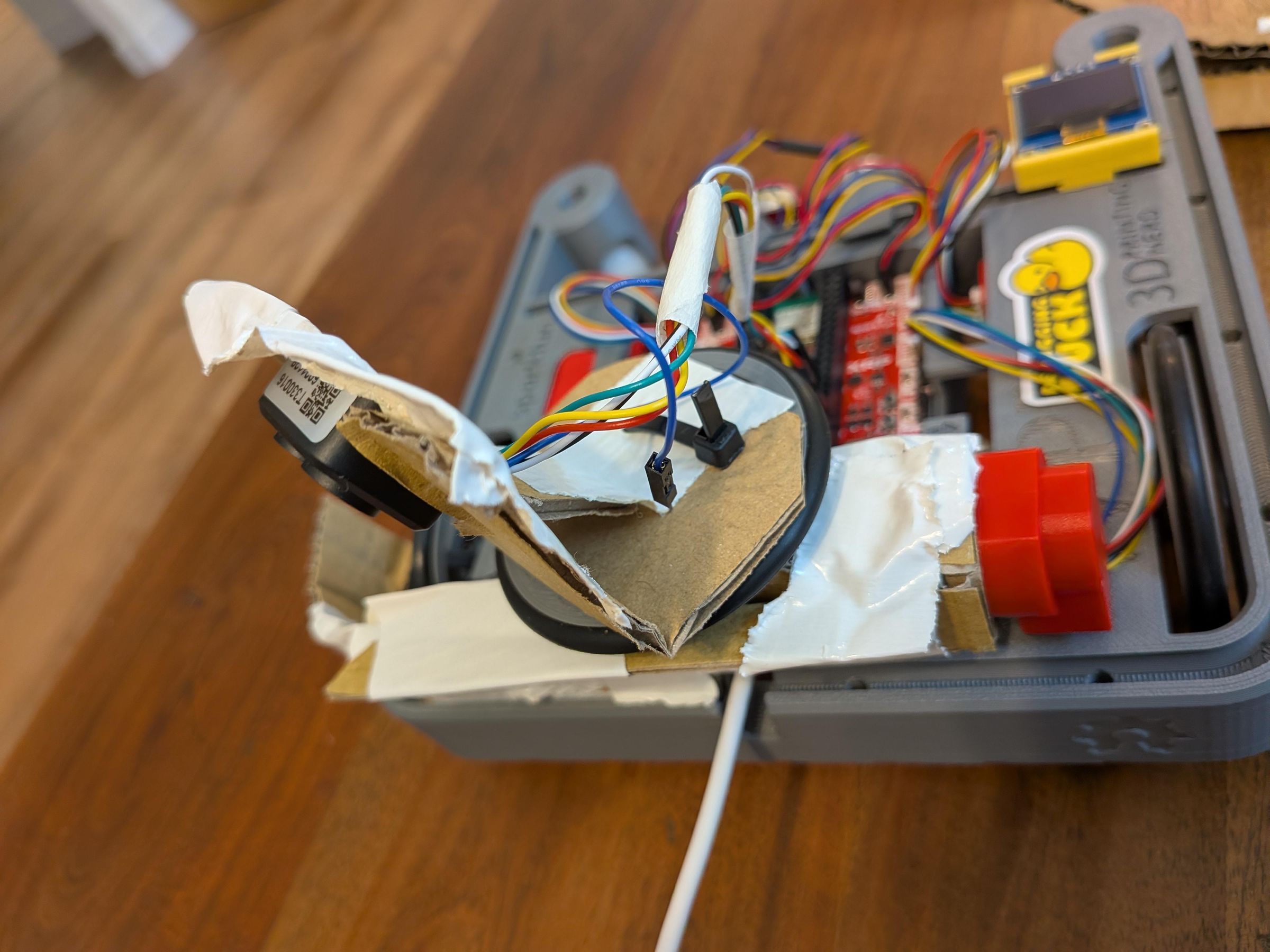
The Lidar mount is used to spin the lidar sensor around so that we get measurements at all angles. we need it because the encoder in the motor is much more accurate than say, the gyroscope on the robot were we to spin the whole thing around.
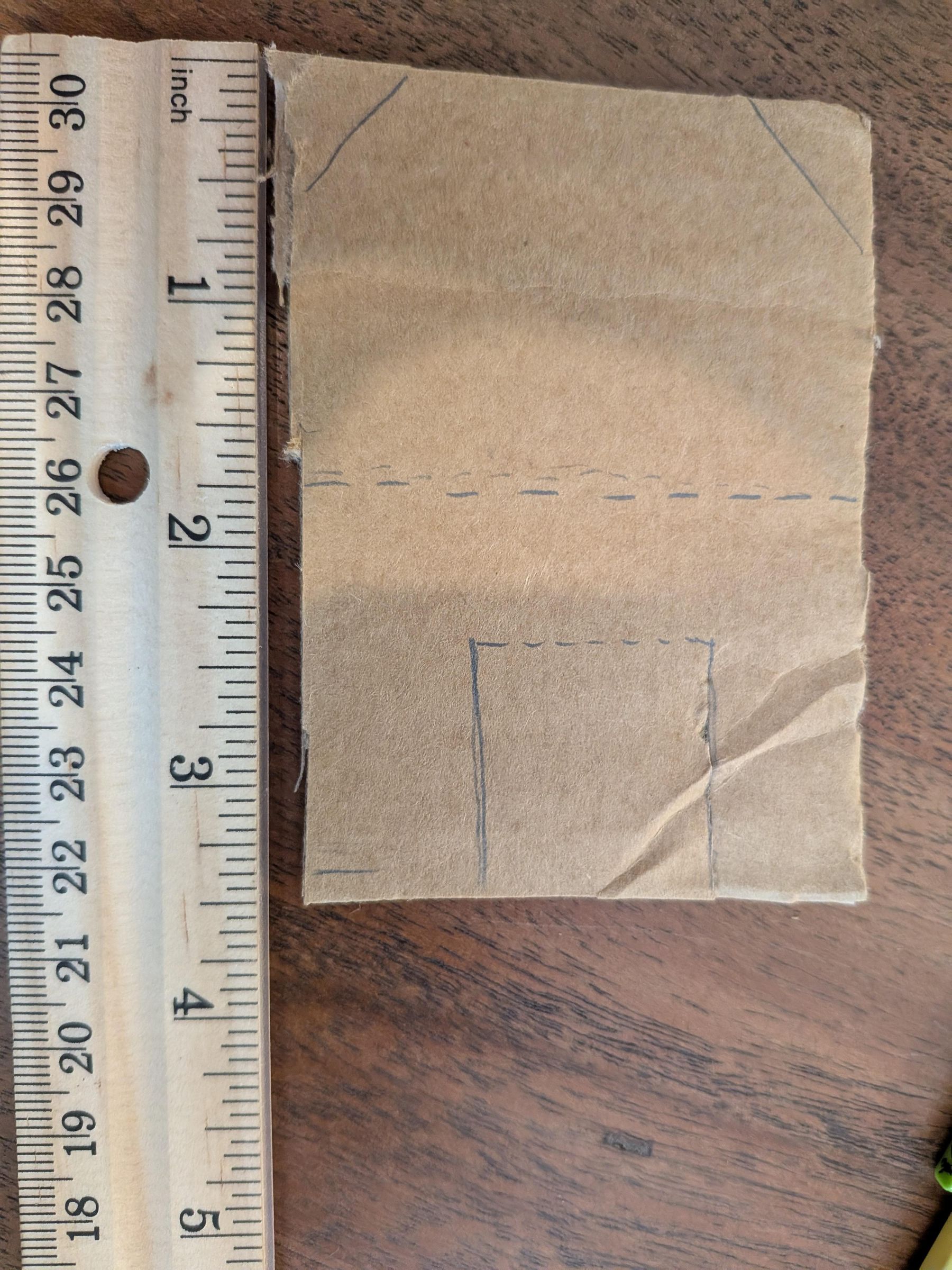
- Cut a 2.5 inch by 3.5 inch piece of cardboard
- Cut this cardboard along the solid lines in the image. Fold the cardboard along the dotted lines.
- Ziptie an XRP Hobby Motor wheel to the part of the cardboard as shown in the image. This is also shown in the image of the final lidar mount.
- Add some tape for extra security.
- fold flap back until it touches the wheel mount. This is shown in the image of the lidar mount. Tape.
- Attach the lidar module to the mount through the opening created by folding the flap in the previous step. this is shown in the final image of the lidar mount as well. Tape.
- Put a small piece of duct tape onto the axle of the motor to ensure a snug fit before attaching the wheel to the motor.
IMPORTANT: The motor and Lidar mount MUST be able to make a full 360 degree rotation without anything bending or any wires getting pulled out.
Code Introduction
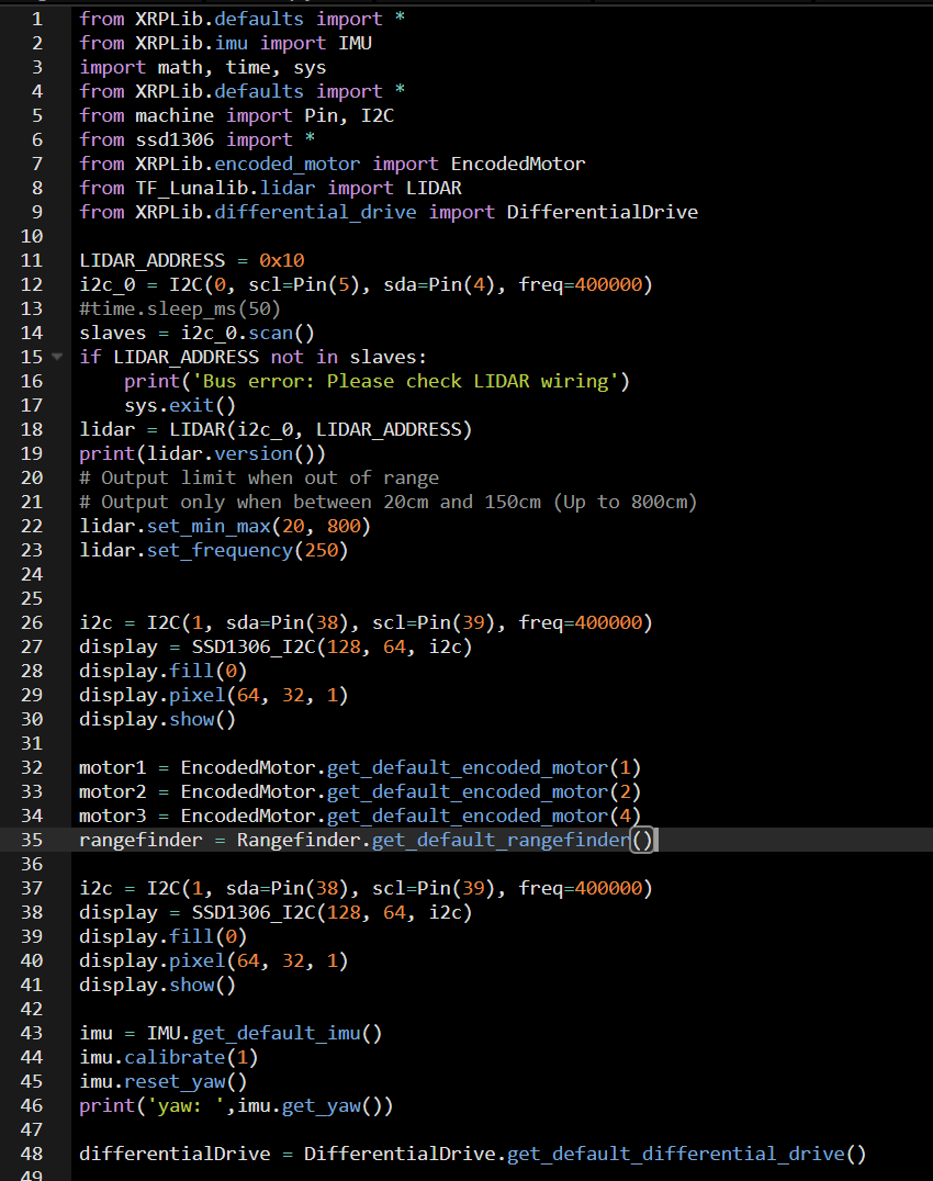
As this is mainly a coding project, the code is to large to go though line by line. Instead, we will go through it section by section, explaining what it does. At the end, we will have the full code for your copy/paste enjoyment.
(Keep in mind, our code is not the cleanest, and resembles spaghetti in some spots. If you want to try and optimize, please do. However, originally, only us and god knew how this code worked, now only God does! So good luck.)
For starters, the first section is the import block, shown in the attached image.
This part of the code simply imports all the required libraries, and defines classes.
As you can see, there are a lot of both.
Random Functions
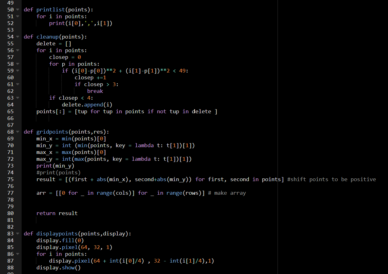
This section of code contains a bunch of random functions used for random things. Some are used in the code, some are for debugging, and some are unused.
Printlist() prints the list of points in a fancy way, so it can be put into a spreadsheet.
Cleanup() cleans up the list of points, removing outliers. This is used after scanning.
Displaypoints() prints the list of points to the OLED display
Gridpoints() is a unused function that would clean up the point list further, if it worked.
Scanning
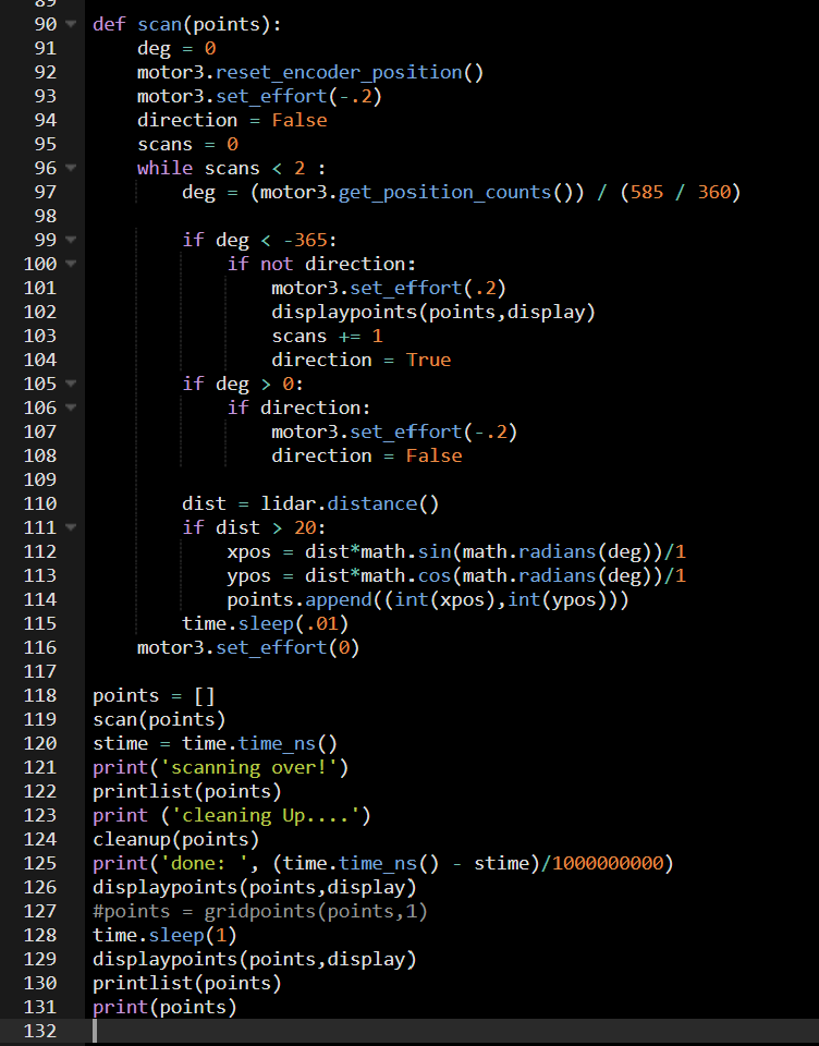
This code moves the lidar back and forth, generating the list of points. It also runs the cleanup function, and measures how long it takes. These functions often take a while, because they have to check every point against every other.
The A* Algorithm
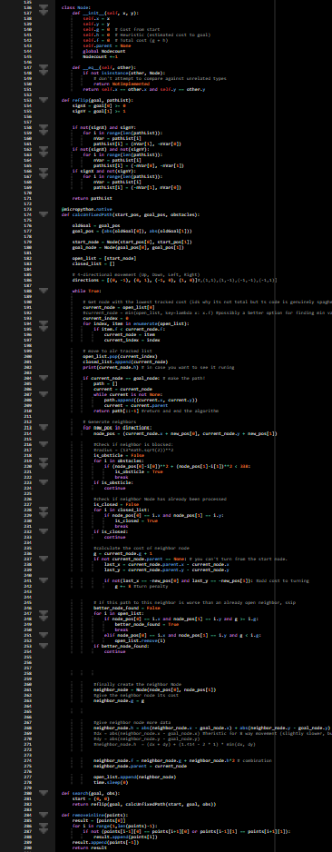
This block of code is the pathfinding algorithm, A*. Make sure to zoom in!
in our demonstration, the start node is set to (0,0), and the end node is set to (0,60). This means that the robot will attempt to drive forward 60 cm. The end coordinate is easily modifiable however, and can be anything you want.
A* works by exploring nodes in order of how far from the start they are, and how close to the end.
Once the robot finds the end node, it follows the path back to the start.
Our big modification is a penalty for turning, so that the robot spends most of it's time going straight. This helps improve accuracy.
The "walls" Variable contains a test list of Lidar points. Useful for debugging!
To learn more about the A* algorithm, visit this website
When this code runs, it will print a series of numbers to the console. These numbers represent the current node's distance to the finish node. Once it reaches zero, the robot will start moving. It will also print both the point list and the path list, which you can copy into Desmos to see the robot working.
This part of the code may take several minutes to run, depending on the position of the walls. Testing on my laptop, it runs in under 0.2 seconds, but the processor on the XRP is much smaller. As such, we have spent a while optimizing it, but it is nowhere near perfect!
I am told that the reflip function may not be necessary and may in fact be detrimental. However, it is currently working, and I don't dare touch it.
Movement
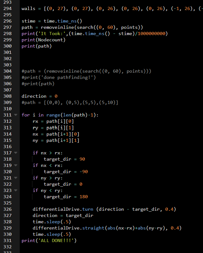
Once the A* algorithm finds a path, the next step is movement. This code makes the robot follow the list of vertices, going to every point. Due to the robots size, and the inaccuracies of the real world, the robot may still clip the edge of the wall. This can be adjusted as a constant in the A* code.
Full Code
#You can copy and past this code into the XRP editor, or simply inspect our work.
#Suggestons welcome!
from XRPLib.defaults import *
from XRPLib.imu import IMU
import math, time, sys
from XRPLib.defaults import *
from machine import Pin, I2C
from ssd1306 import *
from XRPLib.encoded_motor import EncodedMotor
from TF_Lunalib.lidar import LIDAR
from XRPLib.differential_drive import DifferentialDrive
LIDAR_ADDRESS = 0x10
i2c_0 = I2C(0, scl=Pin(5), sda=Pin(4), freq=400000)
#time.sleep_ms(50)
slaves = i2c_0.scan()
if LIDAR_ADDRESS not in slaves:
print('Bus error: Please check LIDAR wiring')
sys.exit()
lidar = LIDAR(i2c_0, LIDAR_ADDRESS)
print(lidar.version())
# Output limit when out of range
# Output only when between 20cm and 150cm (Up to 800cm)
lidar.set_min_max(20, 800)
lidar.set_frequency(250)
i2c = I2C(1, sda=Pin(38), scl=Pin(39), freq=400000)
display = SSD1306_I2C(128, 64, i2c)
display.fill(0)
display.pixel(64, 32, 1)
display.show()
motor1 = EncodedMotor.get_default_encoded_motor(1)
motor2 = EncodedMotor.get_default_encoded_motor(2)
motor3 = EncodedMotor.get_default_encoded_motor(4)
rangefinder = Rangefinder.get_default_rangefinder()
i2c = I2C(1, sda=Pin(38), scl=Pin(39), freq=400000)
display = SSD1306_I2C(128, 64, i2c)
display.fill(0)
display.pixel(64, 32, 1)
display.show()
imu = IMU.get_default_imu()
imu.calibrate(1)
imu.reset_yaw()
print('yaw: ',imu.get_yaw())
differentialDrive = DifferentialDrive.get_default_differential_drive()
def printlist(points):
for i in points:
print(i[0],',',i[1])
def cleanup(points):
delete = []
for i in points:
closep = 0
for p in points:
if (i[0]-p[0])**2 + (i[1]-p[1])**2 < 49:
closep +=1
if closep > 3:
break
if closep < 4:
delete.append(i)
points[:] = [tup for tup in points if not tup in delete ]
def gridpoints(points,res):
min_x = min(points)[0]
min_y = int (min(points, key = lambda t: t[1])[1])
max_x = max(points)[0]
max_y = int(max(points, key = lambda t: t[1])[1])
print(min_y)
#print(points)
result = [(first + abs(min_x), second+abs(min_y)) for first, second in points] #shift points to be positive
arr = [[0 for _ in range(cols)] for _ in range(rows)] # make array
return result
def displaypoints(points,display):
display.fill(0)
display.pixel(64, 32, 1)
for i in points:
display.pixel(64 + int(i[0]/4) , 32 - int(i[1]/4),1)
display.show()
def scan(points):
deg = 0
motor3.reset_encoder_position()
motor3.set_effort(-.2)
direction = False
scans = 0
while scans < 2 :
deg = (motor3.get_position_counts()) / (585 / 360)
if deg < -365:
if not direction:
motor3.set_effort(.2)
displaypoints(points,display)
scans += 1
direction = True
if deg > 0:
if direction:
motor3.set_effort(-.2)
direction = False
dist = lidar.distance()
if dist > 20:
xpos = dist*math.sin(math.radians(deg))/1
ypos = dist*math.cos(math.radians(deg))/1
points.append((int(xpos),int(ypos)))
time.sleep(.01)
motor3.set_effort(0)
points = []
scan(points)
stime = time.time_ns()
print('scanning over!')
printlist(points)
print ('cleaning Up....')
cleanup(points)
print('done: ', (time.time_ns() - stime)/1000000000)
displaypoints(points,display)
#points = gridpoints(points,1)
time.sleep(1)
displaypoints(points,display)
printlist(points)
print(points)
Nodecount = 0
class Node:
def __init__(self, x, y):
self.x = x
self.y = y
self.g = 0 # Cost from start
self.h = 0 # Heuristic (estimated cost to goal)
self.f = 0 # Total cost (g + h)
self.parent = None
global Nodecount
Nodecount +=1
def __eq__(self, other):
if not isinstance(other, Node):
# don't attempt to compare against unrelated types
return NotImplemented
return self.x == other.x and self.y == other.y
def reflip(goal, pathList):
signX = goal[0] >= 0
signY = goal[1] >= 1
if not(signX) and signY:
for i in range(len(pathList)):
nVar = pathList[i]
pathList[i] = (nVar[1], -nVar[0])
if not(signX) and not(signY):
for i in range(len(pathList)):
nVar = pathList[i]
pathList[i] = (-nVar[0], -nVar[1])
if signX and not(signY):
for i in range(len(pathList)):
nVar = pathList[i]
pathList[i] = (-nVar[1], nVar[0])
return pathList
@micropython.native
def calcUnfixedPath(start_pos, goal_pos, obstacles):
oldGoal = goal_pos
goal_pos = (abs(oldGoal[0]), abs(oldGoal[1]))
start_node = Node(start_pos[0], start_pos[1])
goal_node = Node(goal_pos[0], goal_pos[1])
open_list = [start_node]
closed_list = []
# 4-directional movement (Up, Down, Left, Right)
directions = [(0, -1), (0, 1), (-1, 0), (1, 0)]#,(1,1),(1,-1),(-1,-1),(-1,1)]
while True:
# Get node with the lowest tracked cost (idk why its not total but ts code is genuinely spaghetti so whatever)
current_node = open_list[0]
#current_node = min(open_list, key=lambda x: x.f) #possibly a better option for finding min value, but not worth it right now.
current_index = 0
for index, item in enumerate(open_list):
if item.f < current_node.f:
current_node = item
current_index = index
# move to alr tracked list
open_list.pop(current_index)
closed_list.append(current_node)
print(current_node.h) # in case you want to see it runing
if current_node == goal_node: # make the path!
path = []
current = current_node
while current is not None:
path.append((current.x, current.y))
current = current.parent
return path[::-1] #return and end the algorithm
# Generate neighbors
for new_pos in directions:
node_pos = (current_node.x + new_pos[0], current_node.y + new_pos[1])
#Check if neighbor is blocked:
#radius = (13*math.sqrt(2))**2
is_obsticle = False
for i in obstacles:
if (node_pos[0]-i[0])**2 + (node_pos[1]-i[1])**2 < 338: # this const is the distance in cm that the robot stays from the walls.
is_obsticle = True
break
if is_obsticle:
continue
#check if neighbor Node has already been processed
is_closed = False
for i in closed_list:
if node_pos[0] == i.x and node_pos[1] == i.y:
is_closed = True
break
if is_closed:
continue
#calculate the cost of neighbor node
g = current_node.g + 1
if not current_node.parent == None: # you can't turn from the start node.
last_x = current_node.parent.x - current_node.x
last_y = current_node.parent.y - current_node.y
if not(last_x == -new_pos[0] and last_y == -new_pos[1]): #add cost to turning
g += 8 #turn penalty
# If this path to this neighbor is worse than an already open neighbor, skip
better_node_found = False
for i in open_list:
if node_pos[0] == i.x and node_pos[1] == i.y and g >= i.g:
better_node_found = True
break
elif node_pos[0] == i.x and node_pos[1] == i.y and g < i.g:
open_list.remove(i)
if better_node_found:
continue
#finally create the neighbor Node
neighbor_node = Node(node_pos[0], node_pos[1])
#give the neighbor node its cost
neighbor_node.g = g
#give neighbor node more data
neighbor_node.h = abs(neighbor_node.x - goal_node.x) + abs(neighbor_node.y - goal_node.y) # heristic for 4 way movement
#dx = abs(neighbor_node.x - goal_node.x) #heristic for 8 way movement (slightly slower, but can do diagonals)
#dy = abs(neighbor_node.y - goal_node.y)
#neighbor_node.h = (dx + dy) + (1.414 - 2 * 1) * min(dx, dy)
neighbor_node.f = neighbor_node.g + neighbor_node.h*2 # combination
neighbor_node.parent = current_node
open_list.append(neighbor_node)
time.sleep(0)
def search(goal, obs):
start = (0, 0)
return reflip(goal, calcUnfixedPath(start, goal, obs))
def removeinline(points):
result = [points[0]]
for i in range(1,len(points)-1):
if not (points[i-1][0] == points[i+1][0] or points[i-1][1] == points[i+1][1]):
result.append(points[i])
result.append(points[-1])
return result
walls = [(0, 27), (0, 27), (0, 26), (0, 26), (0, 26), (-1, 26), (-1, 27), (-2, 26), (-2, 27), (-3, 27), (-3, 27), (-4, 27), (-5, 27), (-5, 28), (-7, 28), (-7, 27), (-9, 28), (-10, 28), (-11, 27), (-12, 28), (-14, 29), (-15, 28), (-17, 29), (-19, 29), (-21, 29), (-22, 28), (-23, 26), (-23, 23), (-22, 20), (-22, 18), (-22, 16), (-22, 14), (-22, 13), (-22, 11), (-21, 9), (-22, 8), (-22, 7), (-22, 5), (-21, 4), (-21, 2), (-21, 1), (-21, 0), (-21, 0), (-21, -2), (-21, -3), (-21, -4), (-22, -6), (-18, -11), (-18, -12), (84, -70), (91, -66), (38, -20), (43, -19), (43, -15), (66, -3), (67, 0), (67, 6), (66, 10), (66, 15), (17, 28), (14, 28), (11, 27), (9, 27), (7, 27), (5, 27), (3, 27), (1, 27), (0, 27), (-2, 28), (-10, 28), (-12, 28), (-13, 28), (-13, 27), (-14, 28), (-14, 28), (-14, 28), (-13, 28), (-13, 29), (-12, 28), (-11, 28), (-11, 28), (-10, 28), (-9, 28), (-8, 28), (-7, 28), (-6, 28), (-5, 28), (-4, 27), (-3, 27), (-2, 27), (0, 27), (0, 26), (1, 26), (2, 26), (4, 26), (5, 26), (7, 27), (8, 26), (9, 26), (11, 26), (13, 25), (15, 25), (16, 25), (67, 8), (67, 3), (66, -1), (67, -5), (42, -16), (44, -20), (41, -23), (88, -67), (-24, -10), (-23, -4), (-22, -2), (-22, -1), (-21, 0), (-22, 2), (-22, 3), (-22, 5), (-21, 7), (-22, 9), (-21, 10), (-21, 12), (-21, 14), (-21, 16), (-21, 19), (-21, 22), (-20, 27), (-19, 31), (-17, 31), (-14, 31), (-11, 30), (-8, 30), (-6, 29), (-4, 28), (-2, 27), (0, 27), (1, 27), (3, 27), (4, 26), (5, 26), (6, 26), (6, 27), (7, 27), (6, 26), (6, 26), (6, 26), (5, 27), (5, 26), (4, 27), (4, 26), (3, 26), (2, 26), (1, 26), (0, 26), (0, 28), (0, 27), (-2, 27), (-3, 27), (-4, 28), (-5, 27), (-7, 29), (-8, 27), (-10, 28), (-14, 29), (-16, 29), (-18, 29), (-22, 30), (-23, 29), (-22, 25), (-23, 22), (-22, 19), (-21, 16), (-22, 14), (-22, 12), (-22, 10), (-22, 8), (-22, 7), (-22, 5), (-22, 3), (-21, 2), (-21, 0), (-21, 0), (-22, -2), (-22, -3), (-22, -5), (-21, -6), (-19, -11), (-17, -12), (86, -69), (93, -63), (41, -19), (43, -16), (45, -13), (44, -9), (67, -4), (67, 1), (67, 6), (66, 12), (16, 27), (13, 27), (11, 27), (8, 27), (6, 27), (4, 27), (2, 27), (0, 27), (-1, 26), (-4, 30)]
stime = time.time_ns()
path = removeinline(search((0, 60), points))
print('It Took:',(time.time_ns() - stime)/1000000000)
print(Nodecount)
print(path)
#path = (removeinline(search((0, 60), points)))
#print('done pathfinding!')
#print(path)
direction = 0
#path = [(0,0), (0,5),(5,5),(5,10)]
for i in range(len(path)-1):
rx = path[i][0]
ry = path[i][1]
nx = path[i+1][0]
ny = path[i+1][1]
if nx > rx:
target_dir = 90
if nx < rx:
target_dir = -90
if ny > ry:
target_dir = 0
if ny < ry:
target_dir = 180
differentialDrive.turn (direction - target_dir, 0.4)
direction = target_dir
time.sleep(.5)
differentialDrive.straight(abs(nx-rx)+abs(ny-ry), 0.4)
time.sleep(.5)
print('ALL DONE!!!')
Continuation
Now that you have your own working pathfinder, what can you do with it?
That's part of the magic of this project. It works with and complements many other projects!
We have a few ideas for improvements and additions:
- For one, this robot only scans the world once. Can we have it scan multiple times to catch walls that may not be visible from the start?
- Can we make it so that the robot is capable of diagonal movement? The code is already partially in there, you just have to rewrite a few functions for when turns don't equal 90 degrees.
- Can we give the robot a task, delivering things for instance? Can it go back and forth?
- How about we add a Nerf Gun to it for the laughs!
Show us your creations!