Zade: an Extensible WiFi Micro-Rover Platform With Web-UI and Python API, Powered by a Pocket Power Bank
by remandey in Circuits > Microcontrollers
113 Views, 0 Favorites, 0 Comments
Zade: an Extensible WiFi Micro-Rover Platform With Web-UI and Python API, Powered by a Pocket Power Bank
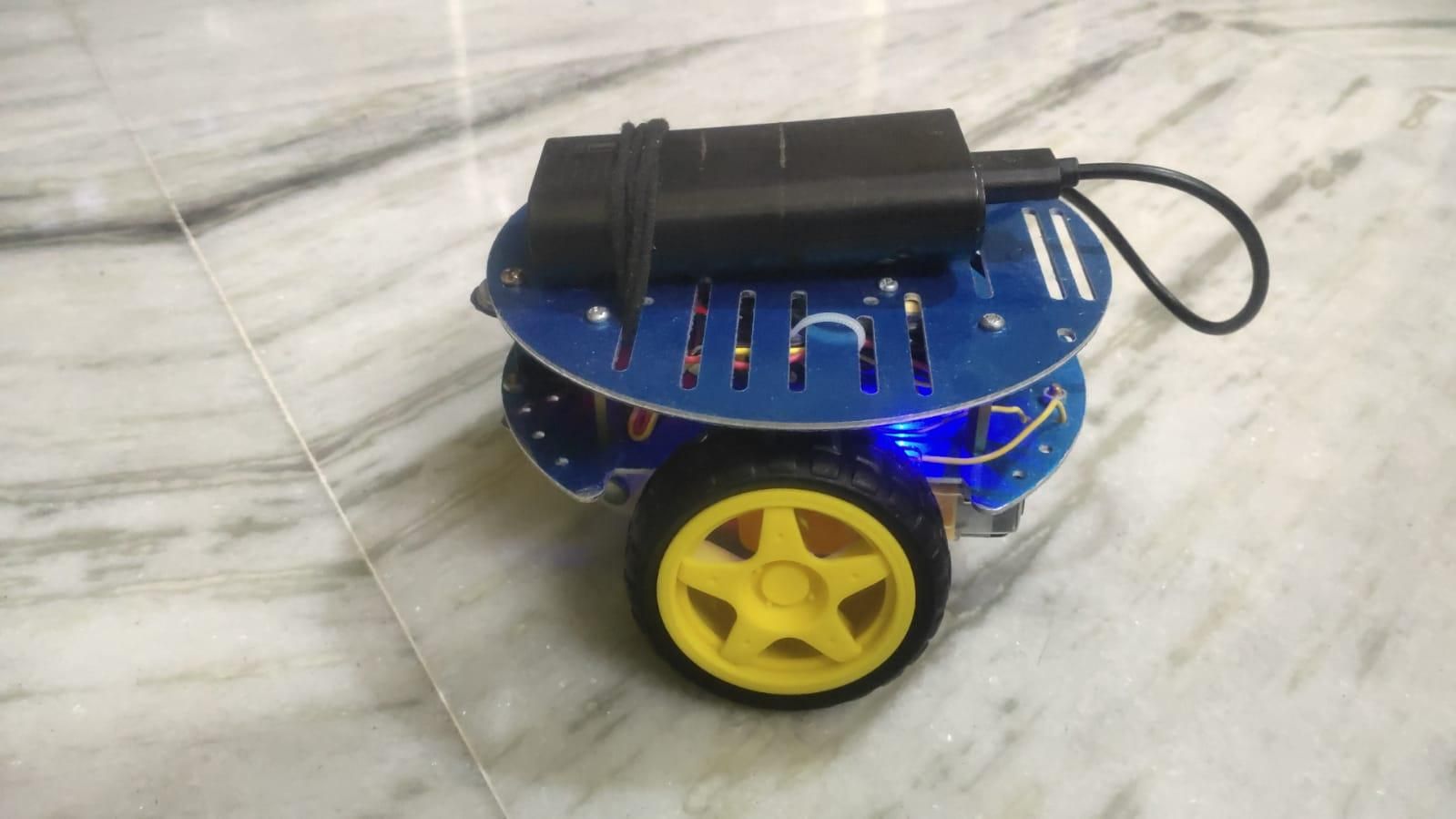
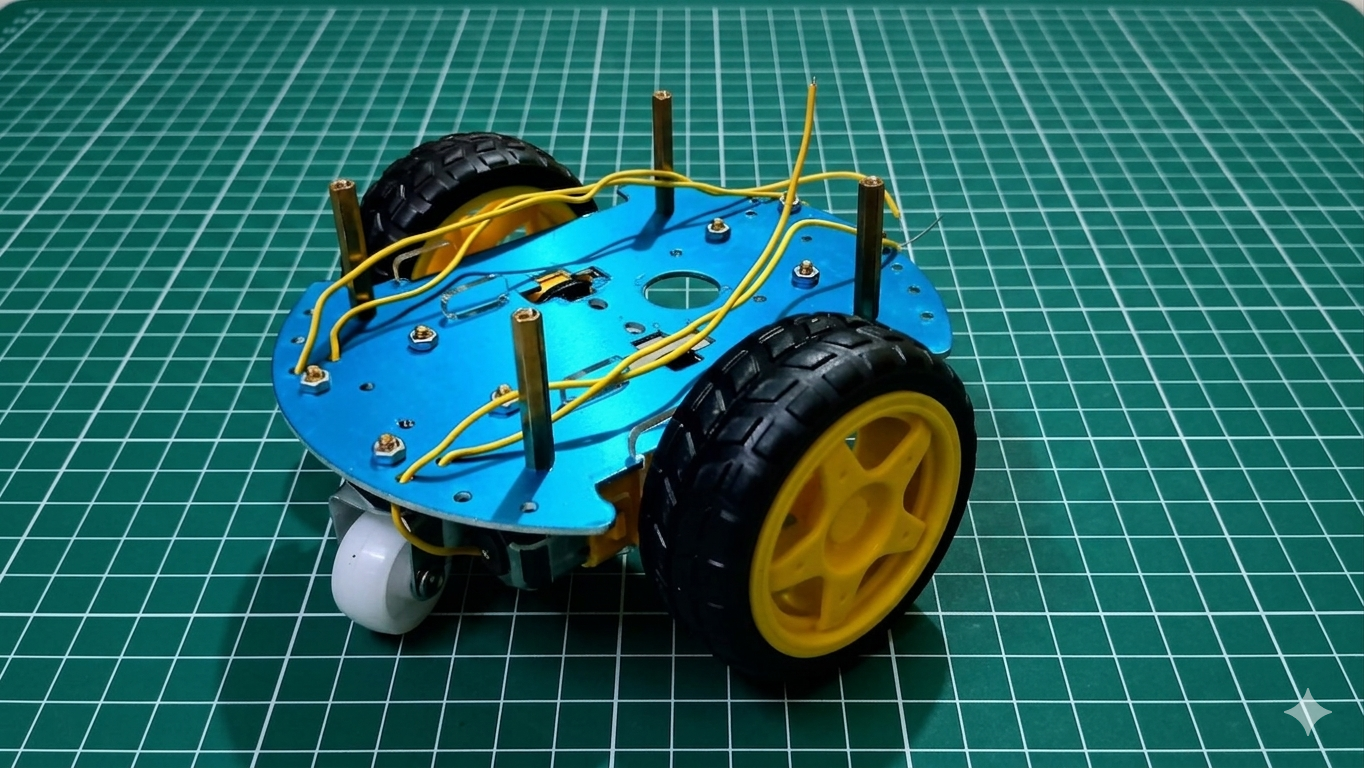
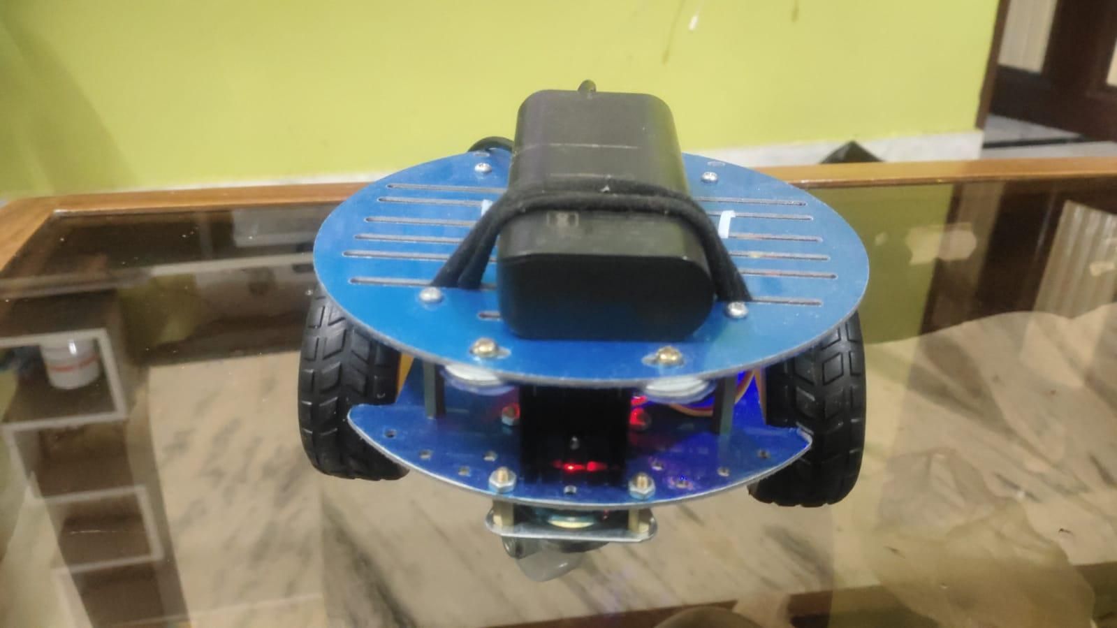
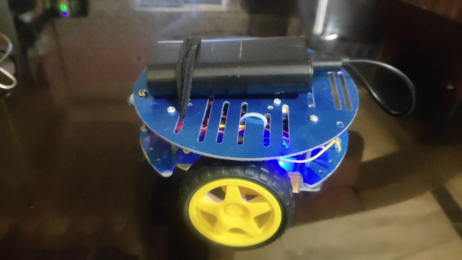
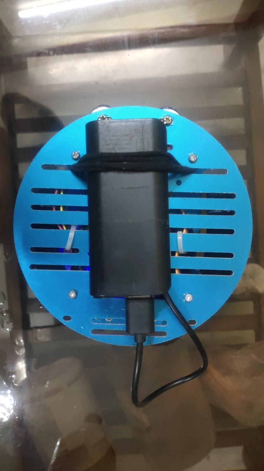
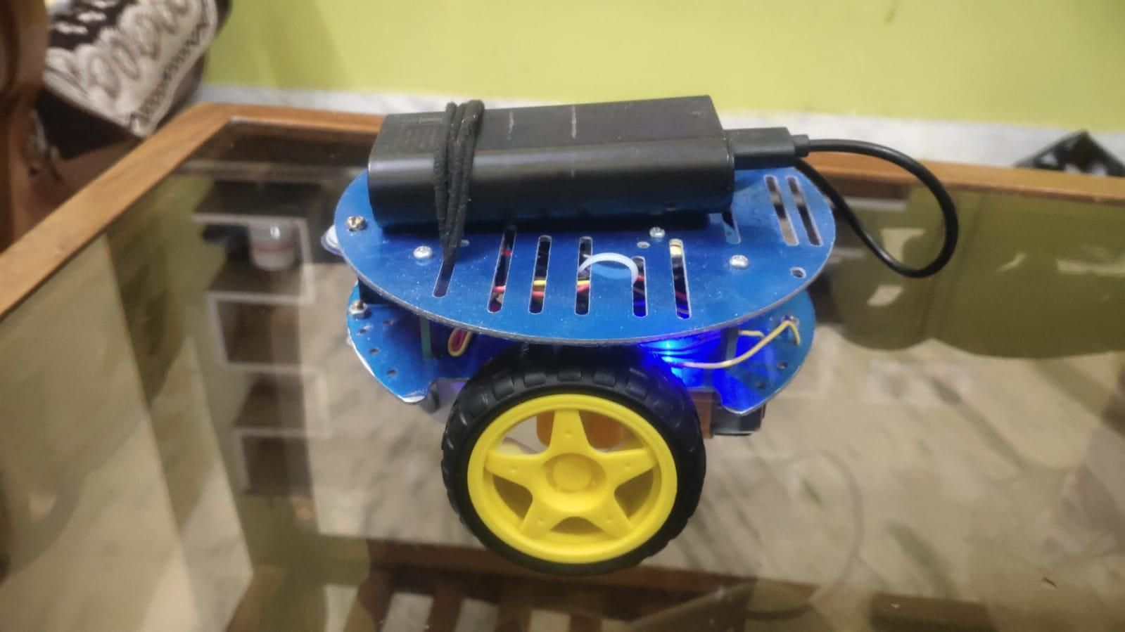
What if you could drive a robot from your phone or laptop — without any dedicated controller, radio transmitter, or bulky battery pack? That's exactly what the Micro-Rover (nicknamed Zade) achieves. Powered by nothing more than a standard 5V USB power bank, this compact WiFi-controlled rover runs entirely on battery and can be steered from any web browser on your phone or laptop.
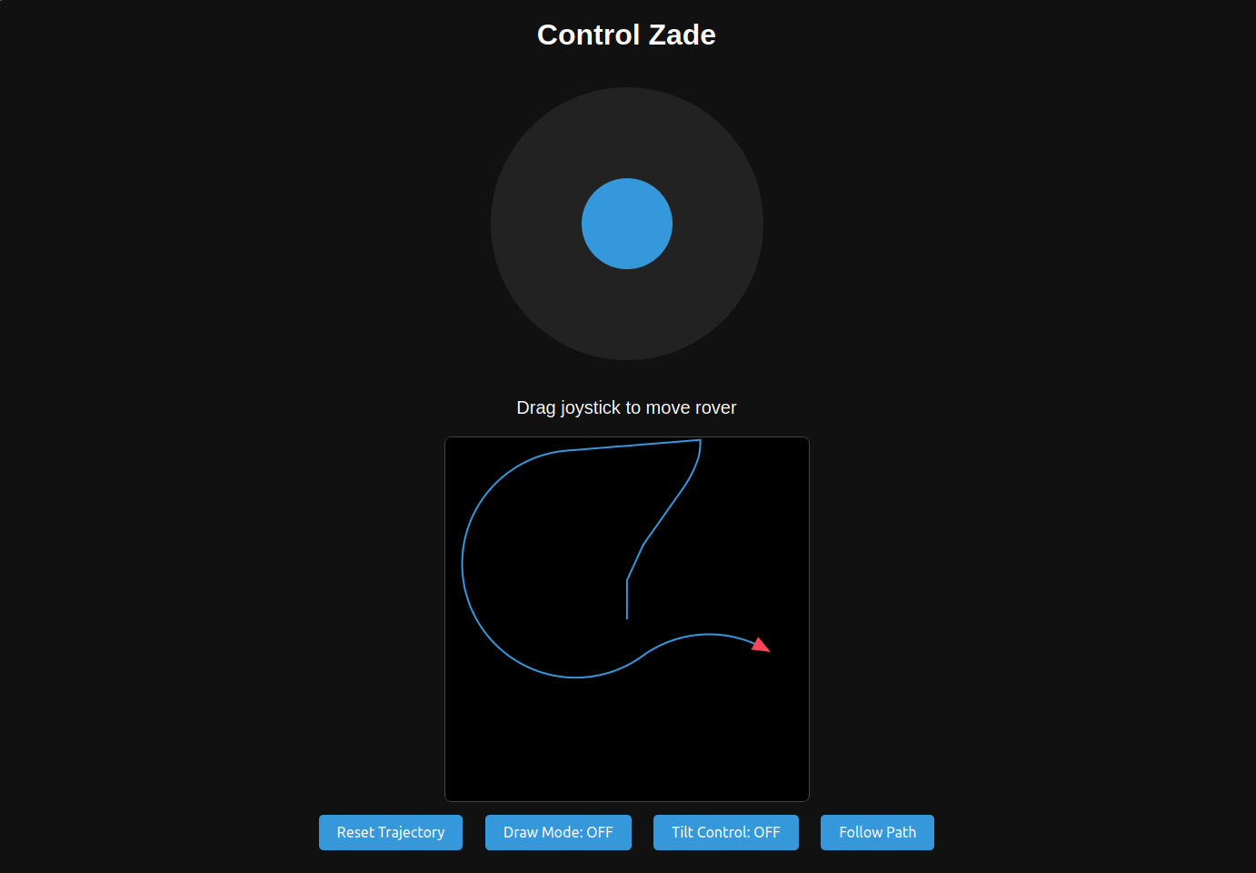
At its heart is an ESP8266 microcontroller — a tiny chip that hosts a full web server and creates its own WiFi hotspot. The rover features a beautiful web dashboard with a virtual joystick, real-time trajectory tracking, a "Draw Mode" where you sketch a path and the rover follows it, and even tilt-to-steer using your phone's accelerometer. All of this runs off a pocket-sized power bank you probably already own.
This project is perfect for the Battery-Powered Contest because it demonstrates how far you can push tiny, efficient hardware: no wall power, no heavy lead-acid cells, just a modern lithium USB power bank keeping an intelligent robot alive and fully operational - and totally inexpensive!!!
Why this Micro-Rover stands out? Lets have a look at the cool features it has!!!
- Truly wireless — any browser = remote control, no app installation needed
- Battery-only — runs off any standard 5V USB power bank
- Draw Mode — sketch a path and watch the rover trace it
- Tilt Control — steer by tilting your smartphone
- Real-time trajectory canvas — see where the rover has been
- Dual WiFi modes — standalone hotspot or home network integration
- mDNS Support — Access the rover via "http://micro-rover.local", without requiring to note ip addresses.
- Python API for programmers — send commands from a PC or Raspberry Pi
Downloads
Supplies
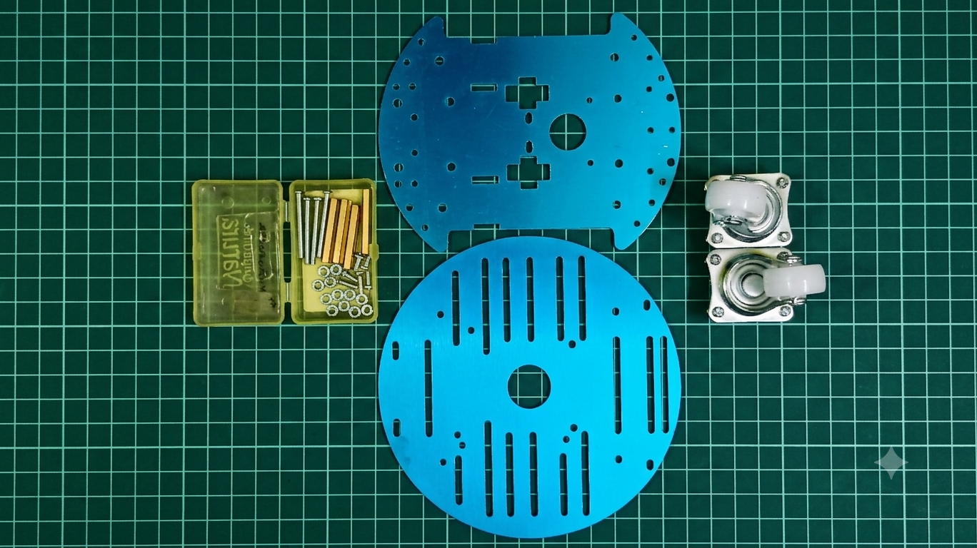
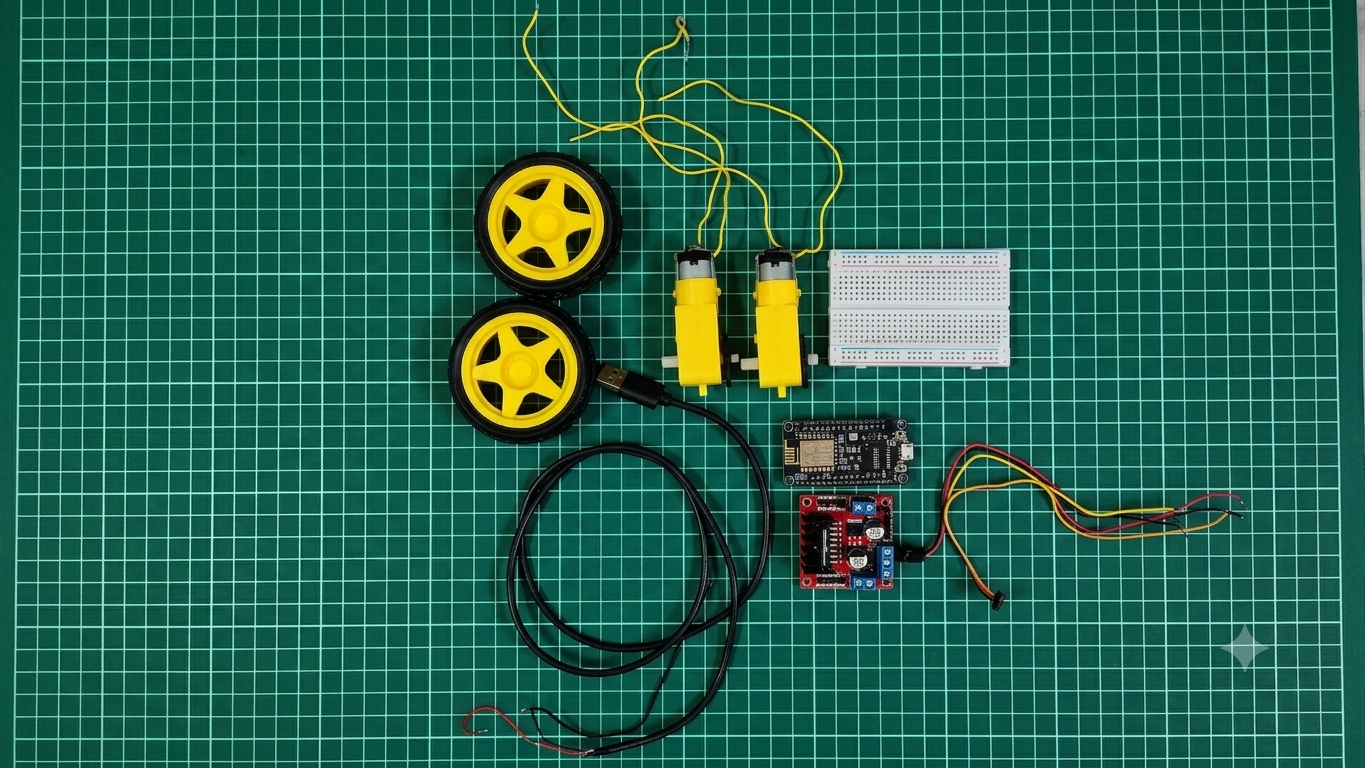
Hardware Components
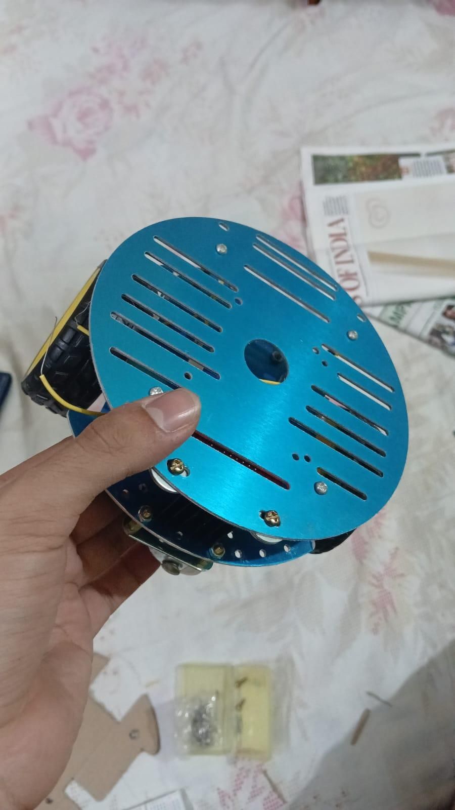
- 2 wheel drive circular metal chassis(top+bottom)
- Screws
- Castor wheels
Electronic Components
- ESP-8266 Microcontroller
- L293N Motor Driver
- USB Cable
- BO Motors with wheels
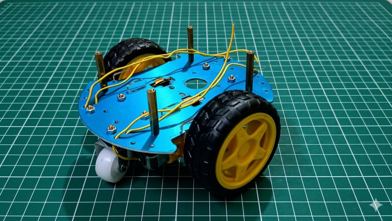
Assembling the Chassis
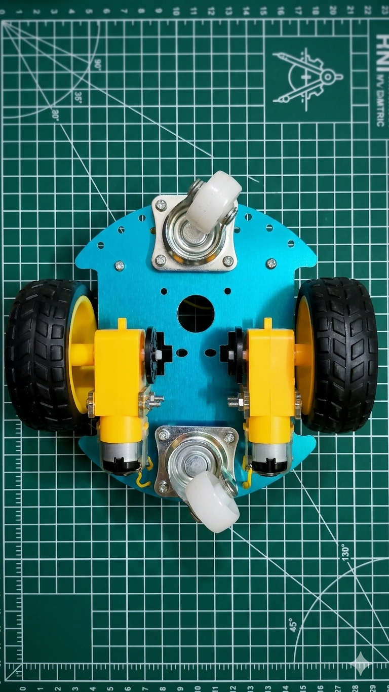
Tools & Fasteners Needed
- M3 Screws (typically 6mm for boards, 10mm–12mm for brackets)
- M3 Standoffs / Spacers (for layering the electronics plate)
- M3 Nuts
- Small Phillips screwdriver
- Double-sided mounting tape or zip-ties
Step-by-Step Assembly Workflow
1. Prepare the Base Chassis Plate
The bottom plate acts as the main structural foundation for the drivetrain.
- Identify the front and rear of your chassis plate.
- Ensure all pre-drilled holes or 3D-printed mounting points for the motor brackets and caster wheel are clear of debris.
2. Mount the DC Motors and Wheels
- Attach the Brackets: Secure the physical mounting brackets for the two DC motors onto the left and right sides of the lower chassis plate using M3 screws and nuts.
- Align and Secure Motors: Slide the DC motors into their respective brackets. Make sure the motor output shafts face outward and are perfectly perpendicular to the chassis frame line. Tighten the bracket screws securely so the motors do not twist under high torque.
- Press-Fit the Wheels: Push the main rubber wheels firmly onto the D-shaped output shafts of the DC motors until they click or sit flush against the shaft shoulder. Ensure there is a 1–2mm gap between the wheel hub and the chassis body so they turn completely unobstructed.
3. Install the Front/Rear Caster Wheel
Differential drive robots rely on a third, non-driven point of contact for stability.
- Position the omnidirectional caster wheel at the front center (or rear center, depending on your preferred orientation) of the bottom plate.
- Fix it in place using short M3 screws. If your caster wheel sits too low and tilts the robot, use small plastic washers or spacers to align its height with the main drive wheels so the chassis sits perfectly level.
4. Install the Electronics Standoffs & Upper Plate
To isolate the delicate microcontroller and wiring from the vibration and weight of the batteries, the rover uses a two-layer design.
- Thread four threaded M3 standoffs into the designated holes on the top side of the base chassis plate.
- Align the upper electronics plate with these standoffs and secure it in place using M3 screws. This elevated platform creates a safe, isolated space underneath for your battery packs while leaving the top clear for your circuitry.
5. Component Layout and Mounting
- Mount the Microcontroller (NodeMCU): Place the ESP8266 development board near the center or rear of the top electronics plate. Fasten it down using small screws through its corner mounting holes (or use high-quality double-sided foam tape if your board lacks mounting holes).
- Mount the Motor Driver (L298N): Fix the H-bridge driver module close to the center of the board, keeping its screw terminals easily accessible. Positioning it relatively close to the motors minimizes the length of heavy-gauge wire needed to connect them.
6. Battery Isolation and Routing
- Place your heavy motor battery pack on the lower deck (underneath the electronics plate) to lower the rover's center of gravity and prevent tipping during quick turns.
- Secure it firmly using a Velcro strap or zip-ties.
- Route the power cables and the motor wires upwards through the chassis cutouts/slots, ensuring they are kept completely away from the moving wheels and the caster pivot assembly.
System Architecture & Understanding the Kinematics
Before wiring, it is vital to understand how the rover moves. Zade uses a differential drive kinematics model. It doesn't have a steering wheel; instead, it turns by varying the speed of its left and right wheels independently.
When you send a linear velocity (v) and an angular steering velocity (ω), the movement resolves mathematically to:
VL = clamp(v + ω, -1, 1)
VR = clamp(v - ω, -1, 1)
On the ESP8266, these values are mapped to 10-bit PWM signals ranging from -1023 to 1023. Positive numbers spin the motor forward; negative numbers spin it backward.
Downloads

Making the Electronics Unit
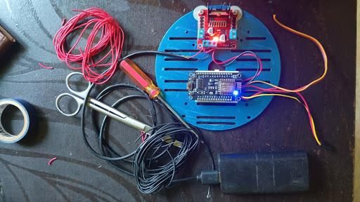
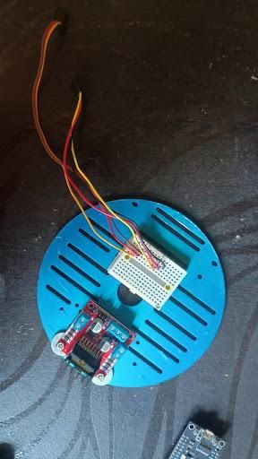
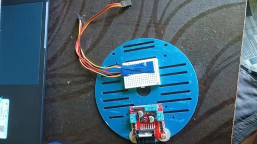
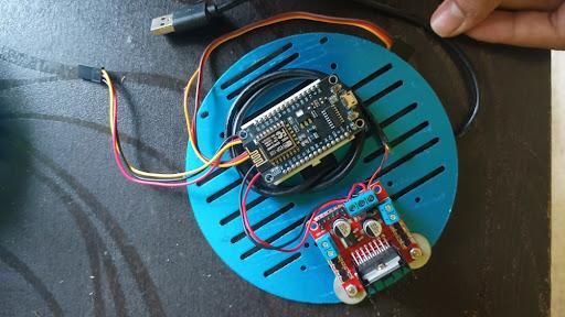
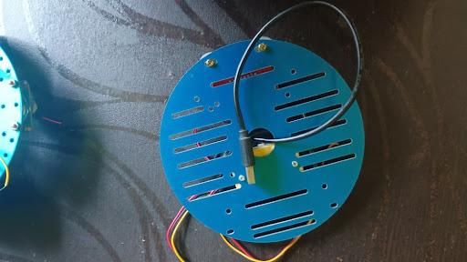
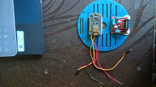
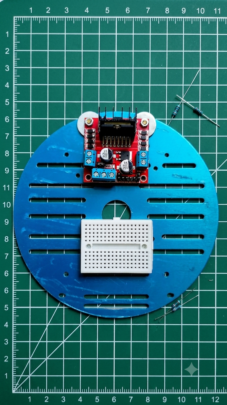
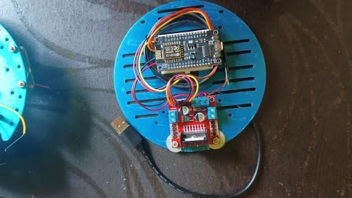
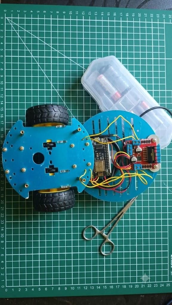
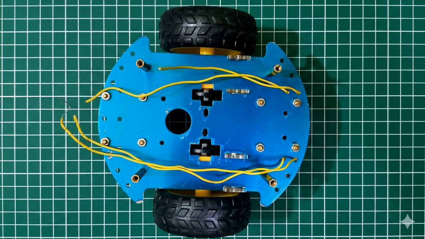
To keep your microcontroller from resetting due to voltage sags when the motors spark up, we must physically separate the logic power from the motor power.
Connect your components according to the table below. Make sure to link all Ground (GND) lines together to form a common reference potential!
ESP8266 GPIO Pin Motor Driver Pin Signal Type Functional Description
⚠️ CRITICAL FAIL-SAFE NOTE: > * Connect your 5V USB power bank only to the ESP8266's micro-USB port.
- Connect your separate battery pack only to the L298N motor driver's power terminals.
- Do not connect the motor driver’s high voltage output back into the ESP8266's 5V pin!
Step 3: Flash the ESP8266 Firmware
The C++ code below handles three critical jobs:
- It spins up a standalone secure Wi-Fi Network (micro_rover).
- It configures an mDNS responder so you can type http://micro-rover.local into a browser instead of memorizing an IP address.
It serves a lightweight REST API endpoint (/move?left=X&right=Y) with an integrated safety timeout switch.
Create a new sketch in the Arduino IDE named main.ino, install your ESP8266 board core, and flash this code:
Testing
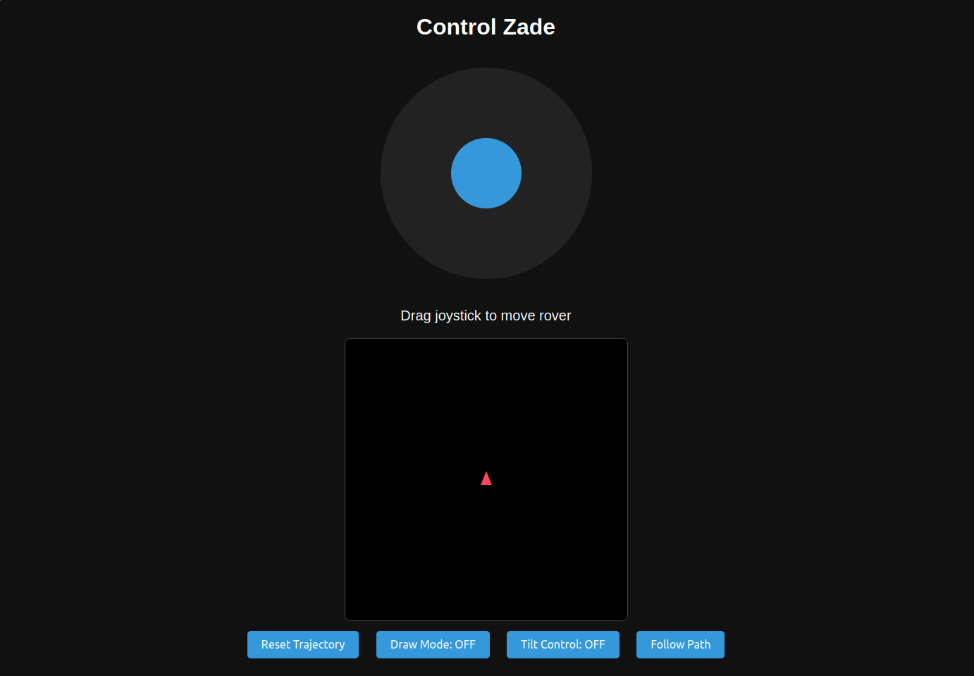

Establishing Control Link
- Connect the host workstation or mobile device to the wireless access point: SSID: micro_rover, Password: 12345678.
- Navigate to http://192.168.4.1 or http://micro-rover.local to start the interface.
Advanced Controls
Automated Python Automation Integration
Clone the repository https://github.com/RemanDey/micro-rover
The scripts/ directory includes interface wrappers for remote script execution:
- keyboard_control.py: Low-latency keyboard command parsing.
- dance_sequence.py: Scripted pattern automation.
- cv_target_tracking.py: Target tracking integration template.
- trace_shapes.py: Geometric path tracing algorithms.
Run and test any of them by :