How to Make Darkness Sensor Circuit
by Amanb48 in Circuits > Electronics
40 Views, 0 Favorites, 0 Comments
How to Make Darkness Sensor Circuit
These darkness sensor circuits flicker less and blinker less high sensitive darkness circuits using the LDR and Photodiode which can be used for the automatic switched ON and Switch off using the light and dark.
Supplies
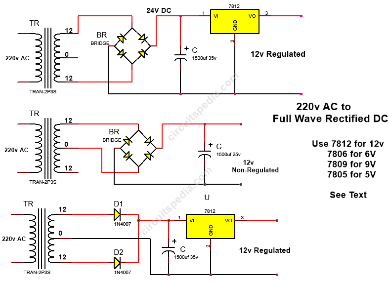
Use a 6v to 12v DC supply using the battery, and adaptor. etc
If you use 12v then you should use a 12v relay and if v then you should use a 9v relay for the switching.
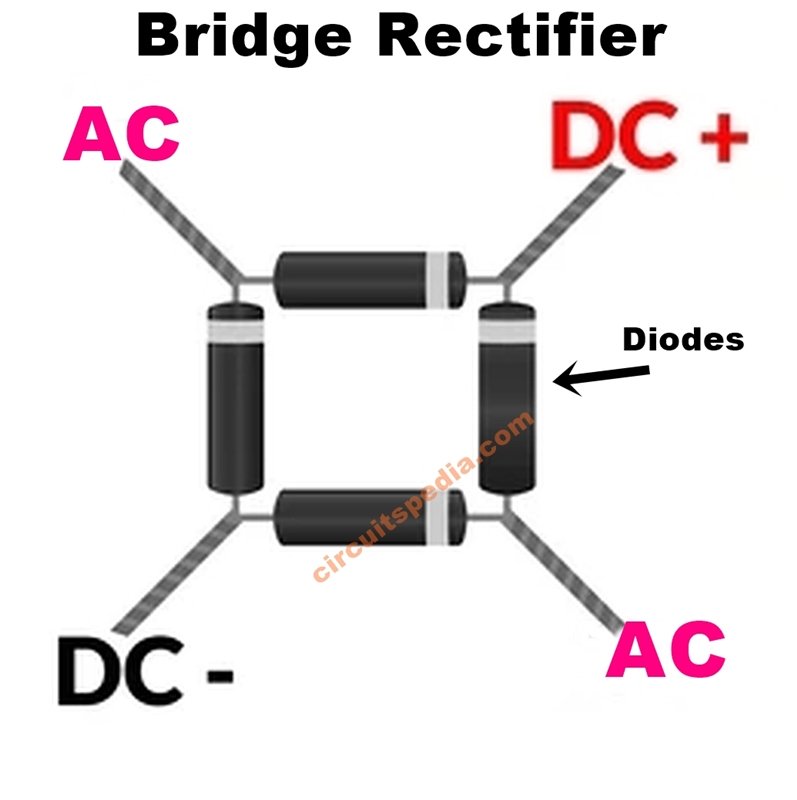
You can also use a self-made full wave rectifier circuit for the project.
Assemble All Parts and Components and Test
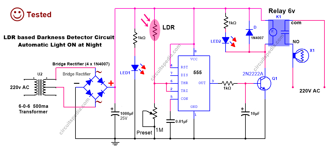
1. LDR Darkness circuit diagram using 555
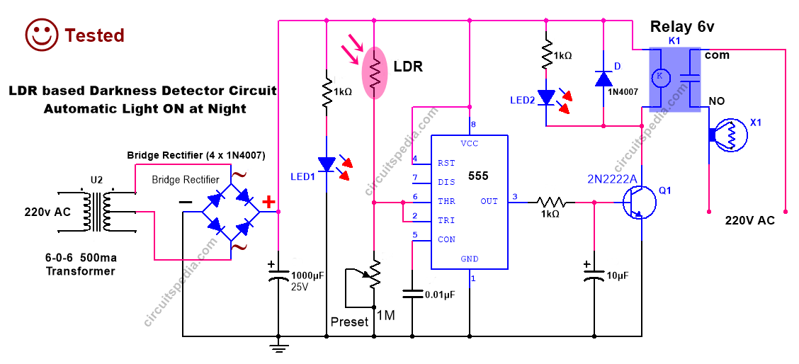
Components
capacitor
1000uf 25v -1
10uf 25v -1
0.01 uf -1
Resistor
1KΩ - 3
LDR - 1
Bridge Rectifier -1 or 1N 4007 diode - 4 pc for making Bridge rectifier
1N4007 diode - 1
IC 555 - 1
Transistor - 2N2222A- 1
Relay 6V - 1
Preset 1MΩ - 1
2. LDR Darkness circuit using the comparator
√ Tested
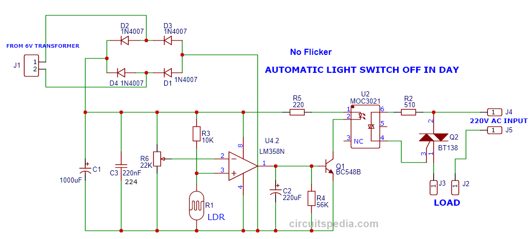
Note- LDR must keep away from the light of the load bulb for flicker less operation. You can do this using the covering of the side area of LDR using black tape.
Demo testing Video Of LDR Darkness circuit using the comparator
Components
Resistors
10K-1
220Ω-1
510Ω or 470Ω -1
56K-1 (Not compulsary)
Capacitors
1000uf 25v-1
220nf (224)-1
C2 = 220uf or 100uf 25v-1
Variable resistor 22K-1
Diode
1N4007-4
Transformer
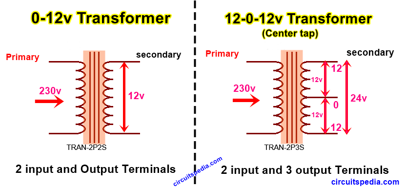
0-6v 500ma- 1
IC
LM358 (comparator)-1
MOC3021 (optocoupler- 1
Transistor BC548-1
Triac BT138-1
LDR (12mm)-1
Download Gerber.dark sensor.zip


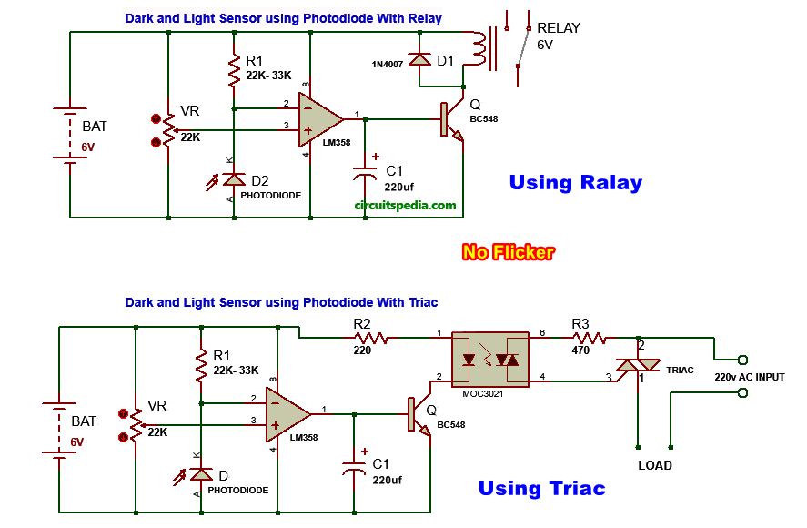
3 &4 . Photodiode darkness circuit diagram
This circuit diagram is made using the photodiode as the light sensor or dark sensor with the lm358 comparator. Highly sensitive and flicker less.
√ Tested
Read More posts of LDR dark sensor circuit
Also Read
Testing of LDR Darkness Sensor Circuit
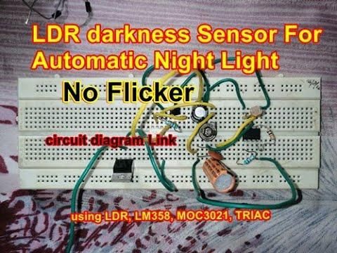
Testing Video of LDR darkness sensor circuit
Testing of PHOTODIODE Darkness Sensor Circuit
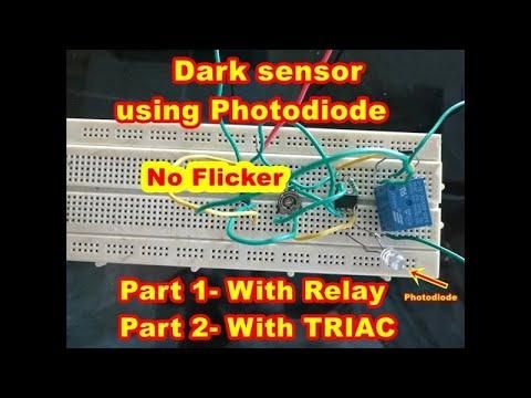
Testing video Of PHOTODIODE Darkness Sensor Circuit